

Phatline
-
Posts
1,285 -
Joined
-
Last visited
-
Days Won
72
Content Type
Profiles
Forums
Blogs
Gallery
Everything posted by Phatline
-

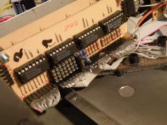
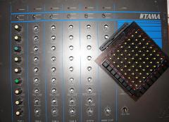
TekkStar Make 058 UI Matrix Resistorchange - plugandplay
Phatline posted a gallery image in Members Gallery
From the album: TekkStar (Tama Techstar Midification)
plug and play: instead of fixed soldered resistors i solderd "pin-headers" (deutsch: stiftleiste) bevore i use 150Ohm Resistors. -
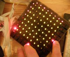
Wired & Programmed if you want the stripped down 8Bit LED-8x8-Matrix Code go there: but it was a long way... after days i plugged the Matrix off, and Plugged two of these on: very good for debugging and codeing... yes and then it worked!!!!!!!!!!! YEAAAAA https://vimeo.com/114452009 (ground hum from webcam...)
-
8Bit Core - C - 8x8 one-color LED-Matrix (like Sid)
Phatline replied to Phatline's topic in MIOS programming (C)
Code with != and 2D Arrays (1D no problem) if((TrgBtnOut[0]==1 && TrgBtnIn[0]==1)){Matrix[0][0] != Matrix[0][0];} :puppeh: humor? Code with =! and 2D Arrays (1D no problem) if((TrgBtnOut[0]==1 && TrgBtnIn[0]==1)){Matrix[0][0] =! Matrix[0][0];} I stay by 1D Arrays. -
8Bit Core - C - 8x8 one-color LED-Matrix (like Sid)
Phatline replied to Phatline's topic in MIOS programming (C)
@TK: i will give it a try if it works - i will post a Stripped Down 2D Array Code its a good Idea, bevore you connect the matrix, to connect simple Diodes, the troubleshooting and programming with that is much easier (if you are an C-NewBee like me) AND it WORKS: https://vimeo.com/114452009 And here is the stripped down 1D-Array code for a 8x8LED-Matrix for 8Bit Core: -
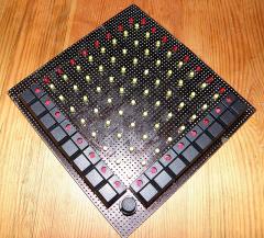
From the album: TekkStar (Tama Techstar Midification)
YES the matrix work! -
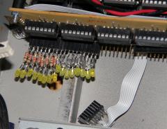
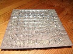
From the album: TekkStar (Tama Techstar Midification)
Test the matrix with simple LEDs bevore connecting the matrix... elsewhere you get very confused by programming and testing... -
thx 4 se work
-
8Bit Core - C - 8x8 one-color LED-Matrix (like Sid)
Phatline replied to Phatline's topic in MIOS programming (C)
ok i dont do this with 2D Arrays - it dont work for me --- --- 1D give me at least no errors schade -
8Bit Core - C - 8x8 one-color LED-Matrix (like Sid)
Phatline replied to Phatline's topic in MIOS programming (C)
3.Matrix-Buttons (2x8 aka 64xVirtual Buttons>the matrix) While i dont have problems with 1Dimensional Arrays. I have massiv Problems with the 2 Dimensional Arrays. following codes are working: if((TrgBtnOut[0]==1 && TrgBtnIn[0]==1)){Matrix[0][7] =! Matrix[0][7];} if((TrgBtnOut[0]==1 && TrgBtnIn[1]==1)){Matrix[1][0] =! Matrix[1][0];} these not: (Matrix[2][0] - Matrix[7][0] making troubles if((TrgBtnOut[0]==1 && TrgBtnIn[2]==1)){Matrix[2][0] =! Matrix[1][0];} if((TrgBtnOut[0]==1 && TrgBtnIn[2]==1)){Matrix[2][0] =! Matrix[2][0];} if((TrgBtnOut[0]==1 && TrgBtnIn[1]==1)){Matrix[2][0] =! Matrix[2][0];} Error: -
8Bit Core - C - 8x8 one-color LED-Matrix (like Sid)
Phatline replied to Phatline's topic in MIOS programming (C)
2. CODE Striped Down: with 1D Array Variables // main.c // 8x8 LED-Matrix-Test // The Program light up all 64 LEDs ///////////////////////////////////////////////////////////////////////////// //Include files #include <cmios.h> #include <pic18fregs.h> #include "main.h" ///////////////////////////////////////////////////////////////////////////// // VARIABLES - - - Description of Variables can be found in void init(void) __wparam! ///////////////////////////////////////////////////////////////////////////// app_flags_t app_flags; // status of app (see bitfield declaration in main.h) unsigned int MtxCount; unsigned int MtxCount_H; int MtxDoutV; int MtxDoutH; int MtxDoutVtmp; int MtxDoutHtmp; int MatrixRow0[8]={1}; //Fill-Initialize the Matrix with 1 > LEDs should ligth up int MatrixRow1[8]={1}; //1D because for me 2D Arrays give me Strange Errors in Mios8 int MatrixRow2[8]={1}; int MatrixRow3[8]={1}; int MatrixRow4[8]={1}; int MatrixRow5[8]={1}; int MatrixRow6[8]={1}; int MatrixRow7[8]={1}; ///////////////////////////////////////////////////////////////////////////// // INITALIZE //////////////////////////////////////////////////////////////// ///////////////////////////////////////////////////////////////////////////// void Init(void) __wparam{ //DIN DOUT AIN Setup MIOS_SRIO_UpdateFrqSet(1); //set shift register update frequency in ms MIOS_SRIO_NumberSet(12); // we need to set at least one IO shift register pair //Set Number of DOUT-Register where the LED Matrix is connected (start by 0) MtxDoutVtmp = 10; //Nr.off Vertikal Shiftregister - 0 is the First Register!!!!!! MtxDoutHtmp = 11; //Nr.off Horizontal Shiftregister - 0 is the First Register!!!!!! MtxDoutV = MtxDoutVtmp * 8; //DOUT-PIN-Calculation: Vertikal Shiftregister MtxDoutH = MtxDoutHtmp * 8; //DOUT-PIN-Calculation: Horizontal Shiftregister MtxCount_H = 0; //Horizontal Counter init > must be 0 > dont Change! } ///////////////////////////////////////////////////////////////////////////// // This function is called by MIOS before the shift register are loaded (every ms) ///////////////////////////////////////////////////////////////////////////// void SR_Service_Prepare(void) __wparam{ /////////DOUT-Matrix-routine///////// //Deactivate Vertical PINs (from last cycle) MIOS_DOUT_PinSet( MtxDoutV, 0); //MtxDoutV= Number of HC595Register - Predefinied e.g.10 MIOS_DOUT_PinSet((MtxDoutV+1), 0); //HC595 OUT-PORTs=8 MIOS_DOUT_PinSet((MtxDoutV+2), 0); //+2 is the 3rd (starting by 0) Pin of this Registor MIOS_DOUT_PinSet((MtxDoutV+3), 0); //so: (10x8=80)+3 = 83.Pin MIOS_DOUT_PinSet((MtxDoutV+4), 0); MIOS_DOUT_PinSet((MtxDoutV+5), 0); MIOS_DOUT_PinSet((MtxDoutV+6), 0); MIOS_DOUT_PinSet((MtxDoutV+7), 0); //Deactivate the last Horizontal PIN (from last cycle) MIOS_DOUT_PinSet(MtxCount_H, 0); MtxCount_H = MtxDoutH+MtxCount; //MtxDoutH=Number of Connected Register*8=Pin Number //Activate Vertical Lines MIOS_DOUT_PinSet( MtxDoutV, MatrixRow0[MtxCount]); MIOS_DOUT_PinSet((MtxDoutV+1), MatrixRow1[MtxCount]); MIOS_DOUT_PinSet((MtxDoutV+2), MatrixRow2[MtxCount]); MIOS_DOUT_PinSet((MtxDoutV+3), MatrixRow3[MtxCount]); MIOS_DOUT_PinSet((MtxDoutV+4), MatrixRow4[MtxCount]); MIOS_DOUT_PinSet((MtxDoutV+5), MatrixRow5[MtxCount]); MIOS_DOUT_PinSet((MtxDoutV+6), MatrixRow6[MtxCount]); MIOS_DOUT_PinSet((MtxDoutV+7), MatrixRow7[MtxCount]); //Activate Horizontal Line MIOS_DOUT_PinSet(MtxCount_H, 1); //Activate First Row - Negatives Side of Diodes //Counter - count from 0-7 then 0 again... if (MtxCount < 8) {MtxCount = MtxCount + 1;} if (MtxCount > 7) {MtxCount = 0;} } void Tick(void) __wparam{} void Timer(void) __wparam{} void DISPLAY_Init(void) __wparam{} void DISPLAY_Tick(void) __wparam{} void MPROC_NotifyReceivedEvnt(unsigned char evnt0, unsigned char evnt1, unsigned char evnt2) __wparam{} void MPROC_NotifyFoundEvent(unsigned entry, unsigned char evnt0, unsigned char evnt1, unsigned char evnt2) __wparam{} void MPROC_NotifyTimeout(void) __wparam{} void MPROC_NotifyReceivedByte(unsigned char byte) __wparam{} void SR_Service_Finish(void) __wparam{} void DIN_NotifyToggle(unsigned char pin, unsigned char pin_value) __wparam{} void ENC_NotifyChange(unsigned char encoder, char incrementer) __wparam{} void AIN_NotifyChange(unsigned char pin, unsigned int pin_value) __wparam{} wy i use MIOS_DOUT_PinSet instead of MIOS_DOUT_SRSet? >because I dont know better! -
8Bit Core - C - 8x8 one-color LED-Matrix (like Sid)
Phatline replied to Phatline's topic in MIOS programming (C)
Variables: 7x 1-Dimensional Array Variable: // VARIABLES //1D Array (Blow Up Code) unsigned int MtxRow0[8]={0}; unsigned int MtxRow1[8]={0}; unsigned int MtxRow2[8]={0}; unsigned int MtxRow3[8]={0}; unsigned int MtxRow4[8]={0}; unsigned int MtxRow5[8]={0}; unsigned int MtxRow6[8]={0}; unsigned int MtxRow7[8]={0}; //Initalize LED-Matrix for(tmpCount=0; tmpCount<8; tmpCount++){ //=0: StartValue, <7: under 7Cycles?, tmpCount++: MatrixRow0[tmpCount]=1; //fill the Matrix to test the hardware MatrixRow1[tmpCount]=1; MatrixRow2[tmpCount]=1; MatrixRow3[tmpCount]=1; MatrixRow4[tmpCount]=1; MatrixRow5[tmpCount]=1; MatrixRow6[tmpCount]=1; MatrixRow7[tmpCount]=1;} //Matrix 1:1 Routing MatrixRow0[0]=0; MatrixRow1[1]=0; MatrixRow2[2]=0; MatrixRow3[3]=0; MatrixRow4[4]=0; MatrixRow5[5]=0; MatrixRow6[6]=0; MatrixRow7[7]=0; or 1x 2-Dimensional Array Variable: Mtx[8][8] //Have ERRORS later in the program // VARIABLES //2D Array (the way to go) unsigned int Mtx[8][8]; unsigned int MtxCount; unsigned int MtxCountOffset; unsigned int MtxCount_H; unsigned int MtxCount_V; // INITALIZE //////////////////////////////////////////////////////////////// void Init(void) __wparam{ //Initalize 2D-Array-LED-Matrix ---Workaround for(tmpCount=0; tmpCount>8; tmpCount++) //=0: StartValue, <7: under 7Cycles?, tmpCount++: +1everycycle {Mtx[0][tmpCount]=1; //fill the Matrix to test the hardware Mtx[1][tmpCount]=1; Mtx[2][tmpCount]=1; Mtx[3][tmpCount]=1; Mtx[4][tmpCount]=1; Mtx[5][tmpCount]=1; Mtx[6][tmpCount]=1; Mtx[7][tmpCount]=1;} Errors on my Way: unsigned int Mtx[8][8]={0}; ergo I cant initalize that way.... nor this way: // VARIABLES --- Global & Local /////////////////////////////////////////////////// unsigned int Mtx[8][8]={{}}; -
8Bit Core - C - 8x8 one-color LED-Matrix (like Sid)
Phatline replied to Phatline's topic in MIOS programming (C)
What I found: -
8Bit Core - C - 8x8 one-color LED-Matrix (like Sid)
Phatline replied to Phatline's topic in MIOS programming (C)
thankz for the tip, but no - not intrested, my matrix is already wired -
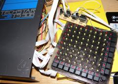
From the album: TekkStar (Tama Techstar Midification)
ready for programming -
Österreich, Schweiz, Deutschland - wo kommst denn her?
-
analog modules that have adresses? (=digital), i dont get you. CV? Trigger? which Resolution the velocity should have? questions after questions...
-
any tips, from which program i can crap the code? the blm code: http://ucapps.de/mios/blm_scalar_v1_0a.zip the LEDs on the Matrix-Board connectetd to J3_1 going to Scalar-Board looking very simular to the SID-Matrix Shematic, except the Transistors, and without the 8 Resistors. & this code is what i see a 8Bit app... so the way to go, i think? A other Idea, get it from the ASM - codet - SID Application SID ASM code: http://ucapps.de/mios/midibox_sid_v2_043.zip because the documentation of "MIOS8 C Interface" says: and under the folder src is a file named: "cs_menu_matrix.inc"" >>> but how to mix that? - where to copy this file, how to load it in the main.c, which command to add and so on. the button thing is clear, but the LED thing where to send my 00 01 02 03 04 05 06 07, 10 11 12 13... not so clear, because of multiplexing... ok in one second that pin and that pin, in the other ms that pin and that pin, but in real code ---pfffuuu to much (newbee) --- but i think that is handled in background, without a need to know (like normal din, out, that in main.c give me notifcation if something happens, or in main c activate a dout pin...) i have more time up tomorrow to get into this, but a quickstart, or a startpoint is really welcome! thankz
-
mein erster gedanke: "Platzhalter" für dinsync ...kabel dran, ihrgendwo auf core, und dann programmieren...nur für alle fälle.
-
code?
-
well anyone had done this up to now? i am starting programming today a 8x8 LED-Matrix (like SID-Matrix, but sid is ASM) , there are some usefull links here! but have anyobody stripped down it already?
-
Paint it Black - to avoid reflections of the Acrylic Overlay. 6Ours or so later (cant say... 2 evenings) I cant help - I am in love The hardware for the TRIGGER-MATRIX-PART is done Well a bit to big... I have to replace 2 Potentiometers of the Clap-Section to the bottum (where is place). even if i mount it 90° there is not enoug place (because of 2Faders left and right to the Matrix) but big is good for my big fingers :phone:
-
From the album: TekkStar (Tama Techstar Midification)
hmmm I have the replace 2 Potentiometers of the clap section ---- no problem, below is enough place for it! a little big is this thing... but it is for PLAYING not for SETUPing ... well with my big fingers. -
From the album: TekkStar (Tama Techstar Midification)
because i realy love it - a shot again :) -
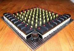
From the album: TekkStar (Tama Techstar Midification)
I love it really I love it! -
From the album: TekkStar (Tama Techstar Midification)
after ours and ours later - the trigger matrix is born