gerald.wert
-
Posts
131 -
Joined
-
Last visited
-
Days Won
2
Content Type
Profiles
Forums
Blogs
Gallery
Everything posted by gerald.wert
-

STM32F4 SDCARD Reading CID failed with status -256! Solved
gerald.wert posted a topic in MIDIbox SEQ
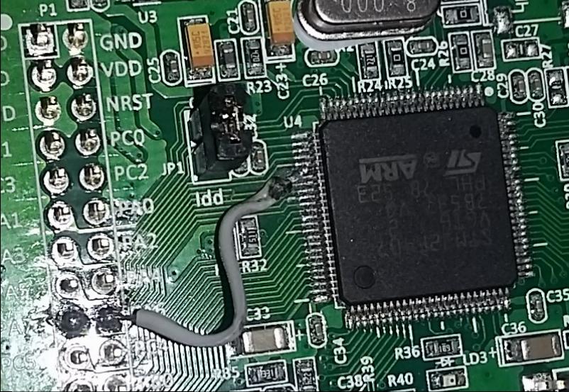
I had been getting the following error from the terminal when trying to access the sdcard on my STM32F4 core: [[35355.231] SD Card Informations [35355.231] ==================== [35355.231] ERROR: Reading CID failed with status -256! [35355.231] ERROR: Reading CSD failed with status -256! [35355.231] [35355.231] Reading Root Directory [35355.231] ====================== [35355.231] SD Card: not connected [35355.232] Failed to open root directory - error status: 12 [35355.232] [35355.232] Checking SD Card at application layer [35355.232] ===================================== [35355.232] Current session: /SESSIONS/DEF_V4L [35355.232] File /SESSIONS/DEF_V4L/MBSEQ_B1.V4: doesn't exist [35355.232] File /SESSIONS/DEF_V4L/MBSEQ_B2.V4: doesn't exist [35355.232] File /SESSIONS/DEF_V4L/MBSEQ_B3.V4: doesn't exist [35355.232] File /SESSIONS/DEF_V4L/MBSEQ_B4.V4: doesn't exist [35355.232] File /SESSIONS/DEF_V4L/MBSEQ_M.V4: doesn't exist [35355.232] File /SESSIONS/DEF_V4L/MBSEQ_S.V4: doesn't exist [35355.232] File /SESSIONS/DEF_V4L/MBSEQ_G.V4: doesn't exist [35355.233] File /SESSIONS/DEF_V4L/MBSEQ_BM.V4: doesn't exist [35355.233] File /SESSIONS/DEF_V4L/MBSEQ_C.V4: doesn't exist [35355.233] File /MBSEQ_C.V4: doesn't exist [35355.233] File /MBSEQ_BM.V4: doesn't exist [35355.233] File /MBSEQ_HW.V4L: doesn't exist or hasn't been re-loaded [35355.233] done. I checked around on the forum and had seen a lot of people having issues with wiring , the card slots and the format on the cards. Mine turned out to be bridged pins under the LQFP100 on the STM32F4 board. Here are the relevant pins if you are having issues as well: LQFP100 P1 PA5 30 15 PA6 31 18 PA7 32 17 PB2 37 24 Here is J16 looking down on it _________ | VS --- VS | -------> to ground | VD --- VD | -------> 3.3V (the STM32 actually only puts out about 3 volts) SI SO | SI ----> PA6 SO ---> PA7 | SC --- SC | --------> PA5 | RC2 RC1 | RC2 --> PD11 RC1-->PB2 (RC1 goes to the onboard SDCard reader or a card on J16 if there is no card in the reader ---------------- RC2 is for a second Card and not needed for most testing. I figured the board was already messed up so I decided to try fixing it. Those pins are super small and hard to work with. There was a dead short between PA6 and PA7 I was able to lift pin PA6 and cut the trace with a razor blade and solder a jumper directly from the pin to PA6. I would think this error would more likely happen from a solder bridge elsewhere and the STM should pass QC. The pins are pretty easy to test as they go straight to the ARM Processor. The also nicely went in order down the side. PA5 was pin 5 on that side of the chip. The white silkscreen on the board makes it a lot easier to keep track of the pins they are marked every 5 pins. The jumper might look a like it is crossing things in the photo but the pin is bent up and out so there is plenty of clearance. I tried solder wik, reflowing the pins, my hot air rework iron, cleaning between the shorted pins with a razor blade, and even removed the header pins hoping the short was there before lifting the pin but nothing else worked for me.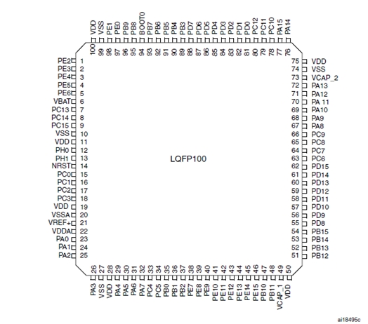

-
I have Two Native instruments Maschine controllers. One is a micro but the other is the regular one with a midi port. I was thinking about trying to use it as a CS for the MB seq. Would it be possible to write more than a basic sequencer as a script or is it going to have too much latency? I had thought to use it as a CS for the full sequencer but there is not a full midi map to the sequencer. I have a STM32F4 and 2 midi boards built waiting for the SEQ v4 boards to be back in stock but this might be a more interesting use for it if it would work.
-
I used one not that long ago. Here is my post if it helps you out: http://midibox.org/forums/topic/20087-lpc1769-rev-d-board-how-to-load-bootloader/ The main thing to be aware of is in the newer boards the pins moved a little if you can align the pin headers before you solder them you should be ok. Also on the new board you do not have to remove the programmer or cut any traces just remove the jumper. I have been using mine as a midi interface for a while now and it works great.
-
LPC1769 rev D board how to load bootloader
gerald.wert replied to gerald.wert's topic in Parts Questions
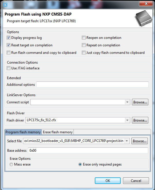
I am not sure if anyone is going to end up with one of these it has been mostly replaced at this point. If you need to replace an old lpc core or end up with one somehow this is what gets it going. Here are a few more details: This is for the LPC expresso 1769 revision D that mouser is selling. The revision D has the same issue as the revision C being that the pins are shifted. It will go into the board but is not a easy fit. The revision D has DAP and will not be found by the older recommended versions of the IDE. I used the currently current version 8 of the IDE. You go through the process of setting up a new project and selecting the 1769 board. There is no option for RTOS project in version 8 just select a C project. You are just getting access to the Flash button so it really does not matter too much here except selecting the right lpc 176x board. Select your current mios boot loader bin file to load. The tricky bit here to get it all to work is you have to set a target address with the newer version of the IDE. There is more than one place a boot loader can be flashed on the newer revisions of the LPC board. After some time spent RTFMI, I found that the base address of the boot loader is 0x00. There is a line to add this at the bottom of the program flash page. Press ok and away it programs. After the reset the multi color led will flash red three times and switch to green. At this point you can put the core in your board and power it via the USB on the LPC core module board. I have not flashed my application yet but it comes up properly in mios studio. I have not broken off the programmer yet and everything seems to be working properly with it still attached and the line from the programmer not cut. on the older core this had to be cut or removed for the programs to boot. I will update when I have some more time to get the program loaded and verify functionality as it is.
-
I am trying to finish a build on a midibox that is built around the older smash TV LPC1769 board. Mouser no longer has the recommended revision A or B board and I have not been able to locate one for sale. Mouser offers up this new board EAX00242 ( revision D) as a replacement for the previous board. I have so far been unable to flash the bootloader to this board. The board is not found by the older recommended 5.26 version of the LPC IDE. It is found by the new version 8 of the IDE but it errors when trying to load the boot loader bin This is the error: 95: must set -load-base or --area with binary file I do not see any place to set this info in the IDE and am not turning anything up with google search or on the forum here.