gerald.wert
-
Posts
131 -
Joined
-
Last visited
-
Days Won
2
Content Type
Profiles
Forums
Blogs
Gallery
Everything posted by gerald.wert
-
The one I linked to does not get hot. Some of the pin compatible ones the regulator on them may get hot but it should be accounted for in the design. Note some of the pin compatible ones may need 9 or 12v and not just 5v you will have to check to see what it needs. It all depends on what you end up. You will want to load the siwin sid firmware on the pic. It gives a few extra wave forms with it and it is possible to add a few more if you know how to program, that is beyond my programming ability though.
-
Swin sid is all 5v and you do not have to worry about letting the magic smoke out on a first time build as much as with a sid chip. Good working sid chips have gotten quite pricy the last few years. I bet you already have a 5v regulated ac adapter too if you check you cell phone adapters. Be sure to use the 9v regulator for the 8580 and test all the voltages before putting you sid and pic in. Everything is built in on the 8 bit core for the sid except the din in and out for buttons and leds. You will want an eprom for storing patches too but do not need one to get started. I highly recommend you build the minimum control surface with the buttons, screen and encoder. You will be able to access all the functions from there and if you have to trouble shoot anything it will be easier to see that it is turning on and booting properly. You should be able to build it on vero board for $10.
-
Yes it should not have been a problem. There should not really be more than 5v on a through jack. It is not a good practice as you are bypassing the isolation though and could be a cause of unexpected issues. Since your setup is working every time with your 1gb card it is possible that with the larger cards what is happening is that it is taking too long to read the card during startup and it is failing due to not loading the configuration on the card. If you partition your larger cards with a 1gb partition that may be a workaround for it. Fastboot may help as well and would be worth checking. Fastboot will give 3 extra seconds at startup if it is turned off. [21469.211] set fastboot <1 or 0>: if 1, the initial bootloader wait phase will be skipped (current: 1) It should be set to 0 to turn it off. here is documentation on accessing the boot loader: http://ucapps.de/mios32_bootstrap_newbies.html
-
Maybe there is a block addressing issue on the larger cards? Is it possible to partition the card with a 1gb or 3 gb partition if you need the space and see if it the card is working when it sees a smaller partition? You could get some weirdness pluging into the MIDI through as the 5v is coming from different places. Should still work though. If it was plugged into one of the midi out ports that is 3.3v than might cause a bigger issue but I believe all the pins are 5v tolerant so should not be a big problem. Seems like you are getting proper voltage with no dip or noise on it though. https://cdn.sparkfun.com/assets/learn_tutorials/4/0/8/midihw.gif
-
You can run two sids per core8 to get stereo and chain up to 4 core8 for 8 sids. One sid per sid module. I would also build at least one bank stick you can do it on vero board for patches and I would get an LCD and a din in X4 for the minimum control surface or you can also build a din in x2 on vero board pretty easily. The din in x4 would be better as you could choose a few more buttons or knobs to add. I may be wrong but I believe the genesis synth is still a work in progress and not a full synth and it needs a core32 not a core 8. I would recommend building a dual swin sid to run on your second core. I like the sound of it a lot and that would let you run two different stereo sid engines say a bass line engine and a lead engine at the same time. It would give you a lot more flexibility. check this post for more details: http://midibox.org/forums/topic/20921-n00b-question-before-etching/#comment-182490 Note you can use the nano swin boards that are floating around and put those "sid chips" in sid modules (be sure to build as 5v sid modules) but the board I posted here is a lot easier to solder up (through hole only) and it will take up much less space if that is a concern.
-
I am pretty sure you will find that your 3.3 supply is running low especially if you are running the 4 midi outs with long cables on each one. The LF 33 CV is only rated at 500ma and I think you really might look at something like this to alleviate your issue: https://moroccodave.com/2017/10/04/diy-midi-thru-box-version-2/ http://m.bareille.free.fr/midithrubox/midithrubox.htm This would take the load off the 3.3v power supply on the sequencer. Especially helpful if you are using 3.3v backlit lcd displays you could really be pulling the 3.3 down a lot. Especially if you have patched things up with some 20' midi cables. 3.3 works but is not the best for midi anyway (some synths and midi line powered midi devices have issues with it) and the 5v would have less loss over the cables and not be affecting your processor as the power supply will be off loaded and buffered to the 5v power of the through box. The lpc supports up to 4 midi in and out already so this would likely be a better solution than the iic midi. You might also like how it simplifies your midi cabling. Or of you are using 5v backlit LCD with a high current drain you could be having trouble supplying the 3.3v regulator with enough power on startup creating all sorts of weirdness. (oleds are pricy but would help a lot here) Might be worth scoping a comparison of the 5v and the 3.3 v on startup to see what is happening there. I am just guessing a bit here not knowing what hardware you have sourced and built.
-
See here to see what I am talking about spikes on startup: https://www.pololu.com/docs/0J16/all
-
I am not familiar with that software but you want to see what your 3.3 is doing. Is it actually 3.3 at startup? Maybe something is pulling it down or it is not actually 3.3v are you getting some noise on the 3.3 line. You should not need to export it but just take a picture of the screen. You should be able to test most of this with a voltmeter but if it is happening right at startup the meter might miss that and will not show a spike or excessive noise. Does it dip on startup, does it have a big pulse on startup? Also when you have all your devices connected when the problem is occurring is the voltage still 3.3v or it could say be dropping below 3v causing your problems. Maybe part of your circuit has a solder bridge or bad cap that is pulling the voltage down. The thought on the midi io versus the iic midi is it would be using a different 5v power supply so may workaround what ever is pulling the voltage low if the voltage is being pulled low somehow say by a midi cable or connected device that is going bad and is loading the system. Don't rule out issues on the processor board either get out a magnifying glass, your volt meter and test everything back to the processor pins for the sd card. Also test with it not powered for impedance. I have had a stm32 board that had a pin for the sd card with a solder bridge new from the factory at the mcu leg it is possible and fixable by lifting the offending pin leg. (they are really small and hard to work with don't mess with this unless you have 100% verified it is the issue) Not saying this is your exact problem, especially since you are using a lpc board but I would get the manual for the LPC and check everything like this: http://midibox.org/forums/topic/20396-stm32f4-sdcard-reading-cid-failed-with-status-256-solved/#comment-177754 It could also be a bad solder joint on one of these pins where the connection in intermittent sometimes it is helpful to use the beep function on the meter to locate this issue as the meter will not beep with a very light touch but as you press down slightly if makes the contact good. You should be able to actually see that with your magnifying glass if one of the pins is not wet out with solder. Since your problem is intermittent and not 100% all the time I would be on the hunt for impedance issues and not exactly a full on short between adjacent legs of the mcu as well as all the other things mentioned above.
-
+1 on this :)
-
Have you checked you power supply voltage? If you have a DSO you could look to see what is happening on startup you might be getting a pulse or it could be dipping a lot. Would be interesting to see if it was happening with the Midi_io if the iic midi would resolve the issue.
-
Interesting did the schematic change on the new layout where there is a new cap somewhere that is charging a little longer to delay the startup time of the processor?
-

MDF board to mount control suface compontents... bad idea?
gerald.wert replied to fallenturtle's topic in Design Concepts
It depends how bad the deflection is you may be able to shim it to get enough of the play out or press it to the one side for every hole. If you are using something like a Dremel 220-01 and you drill the first hole with a small 1mm or even .5mm bit you should not have so much wander. You mention mm off above. If you start drilling with a 6mm bit the holes will be all over the place as the crosspoint is likely a mm or two and that will move your work quite a bit and make it very hard to drill a good hole where you want it. You should be able to do that even without the slide if you print and mark your centers on a printed template. They should come out just about perfect with the slide. Test it out on a scrap piece of something and see how it does. Here is a sample picture of the center of the drill holes marked you can use a dot or an X what ever is easier for you.
-
Yes this cost is spot on. I have been looking at these for a while trying to figure out how to get the cost down and have not come up with something better yet closest thing is getting two of the Adafruit Hella and putting a new board in them but it would not be as good of a design as this. but would put the cost of the pads and case at only $400. Adafruit has boards for the pads using the RGB pixels too that look interesting but I remember reading here that scanning a matrix this size in RGB would be too much bandwidth. The app is really nice too but there is just something about having real buttons. Looking forward to building the new design.
-
MDF board to mount control suface compontents... bad idea?
gerald.wert replied to fallenturtle's topic in Design Concepts
If it is in your budget you might want to look into an xy slide for your drill press. perfect aligned holes. You can make your layout in inscape then print it and tape it to a sheet of lexan or plexiglass to see right where to drill. Aluminum is a lot stiffer but has a bit more cost. You will want to attach your panel to a scrap piece of wood so you are not drilling into your xy slide. https://www.ebay.com/itm/mini-Bench-Drill-Press-Vise-Fixture-Worktable-X-Y-Cross-Slide-Milling-Machine/163791745756?hash=item2622bfb2dc:g:jGoAAOSwhgtbx-BX What you are doing will work but you may have some issues with your encoders pushing back through. They make encoders that are threaded that you can put a nut on so this does not happen. I would not recommend gluing them as they will be hard to service. I have been able to also do a pretty good job with printing my layout out with the centers of the holes marked with an x and drilling the first hole with a really tiny bit. The smaller the pilot hole the less error you should have in your finished holes. A self centering step bit is also really helpful for stepping the holes to the size you want. -
Older pics programmer and book on programming
gerald.wert replied to gerald.wert's topic in Fleamarket
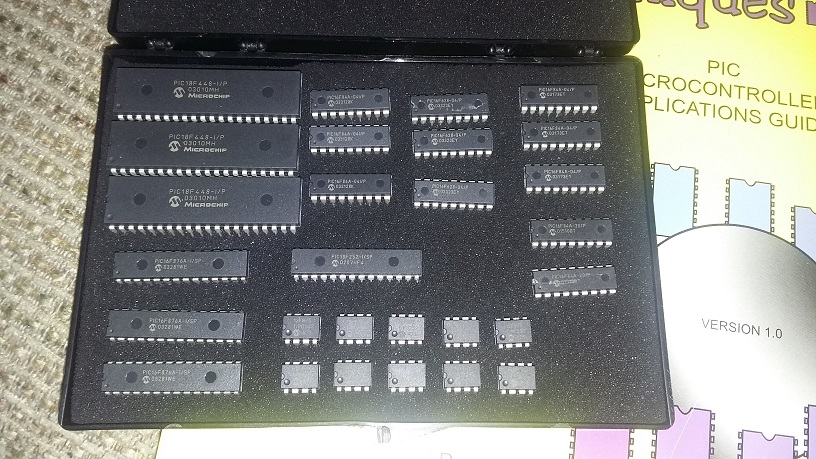
No 18f4685 in there. There are 3 18f448 in there but I am not sure if they are workable. I am not super good at that level of things. Do you have a recommendation on the shipping? I tried usps and fedex and the best rate I could find was $66 that seems way too high. -
Cool Audio just announced a clone of the old 2044 filter chip
gerald.wert replied to jaytee's topic in MIDIbox SID
I started in on this a while back. I have a post I started somewhere. The boards are built but I have not built the CV board yet to hook it up and test it out. The recommended caps are slightly different for the new chips. I think I have the details and schematics in my post. If I can find the time I would like to finish it up and test the caps and r values. -
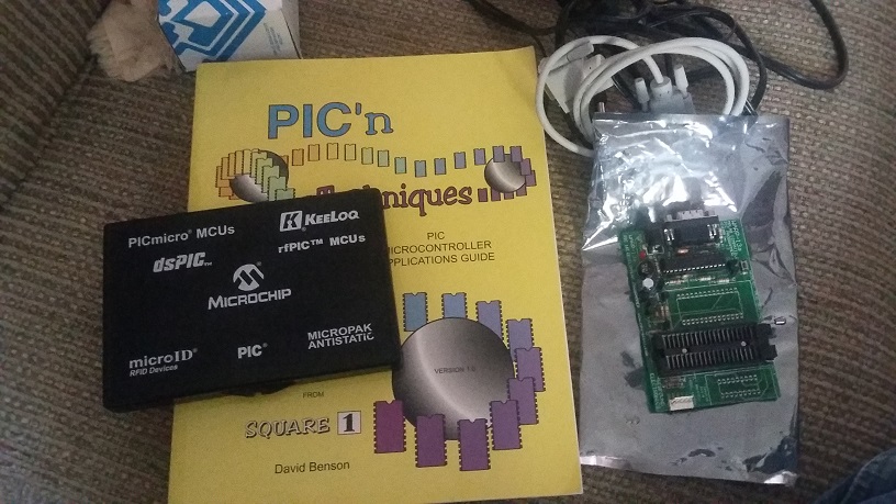
Not sure if anyone here would be interested in this stuff before I put it up on Ebay. I have an old warp 13 pic programmer, several pic chips and PIC'n Techniques a good starter book to pic programming. $20 plus shipping. I think there is about $50 worth of pic chips there. They are all older models but are all brand new. I just do not use it and am clearing out stuff. The programmer works with older versions of MPLab. You will need a computer with a serial port to use the programmer or a good usb to serial converter. All fits in a flat rate USPS box.


-
new to midibox, sourcing parts from mouser help
gerald.wert replied to terrorboss's topic in MIDIbox SID
You might want to think about buying parts from reichelt. The shipping is terrible if you are in the US but the component prices are so much better. If you are putting in a big enough order you will still save a good bit. They also stock better options on audio grade caps. Styroflex and Wilma. If you do go this route I would recommend getting a few extra of really common parts to have on hand as well. Mouser and digikey are nice to order from but you will pay a lot more per component but the shipping is fast and cheap. Worth the comparison especially if you are looking to build something bigger like the 6582. -
Here is the info you need to build the swin sid. There is a typo in the pdf the processor is an Atmegs 8515. Be sure not to get the "a" version of the TDA 1543 it will not work. The red lines are solid links. I thought the 1U caps on the audio output are a bit high and will cause some roll off of the low frequencies but have not changed them and it sounds pretty good as it is. There are some other swin sid designs around but they are surface mount and not as easy to build. This is all through hole parts. I would socket everything so you do not have to worry about over heating any of the chips. If you have the time you could put in sockets for the output caps and experiment with caps to see if it makes a difference. I had a thread with some possible recommended values from the TDA data sheet and I was also asking about how to connect the 1725 series dac. It is a surface mount but is supposed to sound much better. There are extra lines to connect and was not sure where they should go... If you want to try other component values the TDA 1543 data sheet recommends a 3.3nf and a 1.2kr as the filter circuit on the output. This will bring the cutoff much lower and should improve the bass response. Maybe it sounds off or boomy or something though I can not think of another reason for the swin design to be rolling off so high. pcm1725[1].pdf tda1543[1].pdf SwinSIDX2_MB_20090820[1].hex SWiNX22[1].pdf Just saw your reply today... hope this helps you. I think you can source all these parts for under $10.
-
You might be interested in these two files. They are what I used. The Swin sid board is interesting. You may prefer it over building a sid. It does not have the filter bug, has additional voices, custom wave forms and for what sid chips are selling for you can build it as a double sid for less then the cost of 1 sid chip or commodore 64. You also have a much simpler single voltage power supply to think about. The advantages of 2 sids in one box are many here are just a few ideas: stereo, multiple voices, detune for fatter sounds... bankstick edits fliped[1].pdf SWiNX22MC resized and updated[1].pdf
-
Just a thought but if redesigning the core would it be worth it to consider a newer processor? There is a lot of newer technology out there now. I understand the reason not to as there is software dev involved.
-
 Thanks for the details. It looks really great. I have one built and working and will be getting access to a shop bot in a few weeks to make the panel and case.
 -
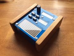
Looks great is that a thin sheet of blue plexi over the clear plexi?
-
You can prototype with just 1 din and 1 dout. Once you have the basic idea up and running you can add to it. Much faster to start with something small and then build on your successes. There is even a matrix pcb that you could bread board a few tact switches for very little $ and have a test environment up and running very quickly. Maybe even a day or two... https://modularaddict.com/manufacturer/midibox/midibox-diomatrix-pcb The only other part you would need is the core and core PCB: https://modularaddict.com/manufacturer/midibox/midibox-core-stm32-pcb Good luck with it looks fun!
-
It looks like you would need 3 Dout in the above diagram or you are not going to have the button count you want. The way it is drawn you will have 3 sets of duplicate buttons. That does not sound like what you want. You could split the lines like you show for the velocity section if you feel you will never want to know velocity if you are hitting the same notes in multiple sections at the same time. This use case for scanning all 3 sections would come up if you were playing cords, slides and if you were playing a bass section and a melody on the other hand. There are likely other use cases if you consider things too. Splitting lines really does not make sense from a design perspective though as the CMOS cost is very low compared to button cost. If you are wanting to reduce components or costs it might make more sense to only start with one section and have an octave button and design with a modular approach where you can add sections if and when needed or wanted. Antichambre is basically saying the same above, hope this is giving you some other thoughts and hints around his initial "Why" question.