gerald.wert
-
Posts
131 -
Joined
-
Last visited
-
Days Won
2
Content Type
Profiles
Forums
Blogs
Gallery
Everything posted by gerald.wert
-

BEGINNER - Problems with INPUTS on MBHP CORE STM32F4
gerald.wert replied to roberto's topic in Testing/Troubleshooting
I am not sure it will work without having a configuration file loading. Maybe you can set DIN up strictly from the console but I have not tried. You can activate DOUT for sure from the console with: "set DOUT 0 1" be careful how many leds you turn on with this command or you can drwls a lot of power. You can build one of these easily: http://www.ucapps.de/mbhp_sdcard.html This SD reader would be good for testing as well. This would allow you to write and test a configuration file. You can access the config files from mios studio to edit it. that way you do not have to take the card out. If you have the default NG configuration loading you should see button presses in the console. If you are getting a lot of noise and errant button presses showing up I would check for shorts somewhere and a swapped connector on your cables or on your boards. . Remember your dout and DIN are on separate channels on the sirio so it is very possible for one to work but not the other if there is an error or bad component somewhere on the other part of the chain. Mainly SI vs SO. If there is a wiring error, sorted trace, or component error that could account for your issues. -
Are you using Seq V4? A8 should be Din clock output A9 should be Din Sync start stop It looks like things changed a bit from F1 to the stm32F4 there is not a J5C. The pins that were A8 and A9 went to PC4 and PC5 on the STM chip. On the F4 core these are output on J5B as A4 and A5 are you able to test to see if you have din sync there? I would think you would still want to add a 741 if there is clock there to protect against shorts and put you at 5v. I am guessing it is not there and the software has changed though as they are no longer labeled A8 and A9 anymore. You should be able to use the SR on your DO too. I am not exactly sure what you are using for DO though. You just need to figure out what SR # it is. If you are using a quad IIc it does not have a shift register on it you have to supply it. Also if you are using the line driver it does not have a SR connected to the din Jack you could connect one though. NG can be super helpful to figure out what number a SR is. You can test for it in the console. Once you find your SR # I believe you will need to set it up on the CV configuration page and in the hardware configuration file before it will work. Definitely interested in what you find out. I have the din sync jack on my Seq on the midi IIc but have not hooked it up to anything yet. I was in the same situation as you where it is a bit more to it and just do not have the time at home right now to sort it out. I do have an Xoxbox with din sync so am definitely interested! I think if you have the line driver if you go here: http://www.ucapps.de/midibox_seq_manual_hw.html and go to the bottom of the page it gives an example configuration that is working.
-
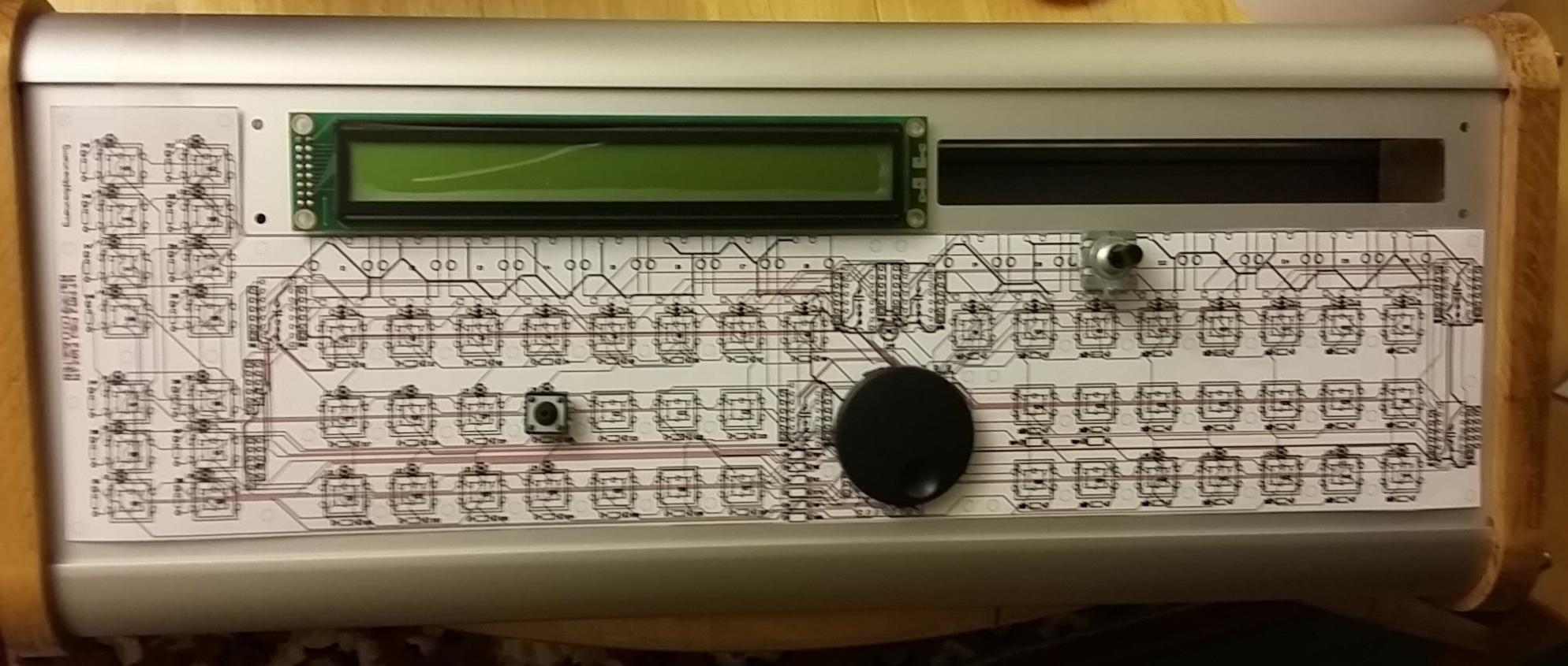
Thanks I do not know much German but the pictures were helpful. I have not built a case for mine yet but have started a layout. It is helpful to see what others have done to build the case.
-
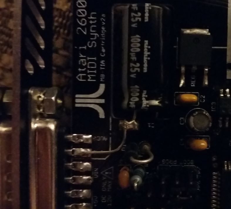
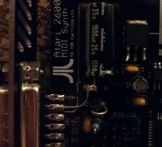
Got the TIa running. The interconnection test is a great tool. Be sure to use it to test your build. You must turn cartridge mode on to build it for the cartridge PCB #define DEFAULT_IS_CARTRIDGE 1 You can test all your connections to the TIA chip with this. I found it super helpful in testing that everything was working right on the board. If I can find the time it might be helpful to add a few of the led meter leds to the test the second shift register chain. I am not sure if there will be another run of the boards or if you will make the board files available. If you do I would add to the build documentation. I just built the entire board in one go. This is definitely a way to do it and should work if you are 100% accurate and good at soldering. I was not so lucky and had a bad shift register to find. It might be super helpful for new builders. and would make for a lot smaller chunks to test and know where there may be a problem if there were some breaks in the build to test.. I think this would be smarter than the way I did it. This is more important on a single board that is using some surface mount components. This might be helpful to add to the build section of the wiki: Build the Power Supply first. test. Build out the oscillator for the pic Build out the midi section Test for connectivity in mios and upload the interconnection test this will test that midi and the pic are working. Build out the led meter Test with the interconnection test if we add a led meter check to the interconnection test. This would check the second shift register chain and led meter circuit Build out the shift registers for the tia Test the tia socket with the interconnection test app This would test the tia socket before you insert your tia. Build out the audio out section and tia clock section. Load the tia test tone app to check your TIA and audio out section or just use the tia firmware as it would already be loaded (Might make sense to skip the test tone app. Easy enough to send a midi note from mios studio) Add the eproms Load Tia Manager to test connectivity and test eproms. Make awesome music! I also found that the hex file on the wiki and SVN would not work for me. My core would become unresponsive after loading it. I spent a bunch of time searching for a problem in my build that was not there. Everything worked correctly with the interconnection test. The board would lock up when loading the Tia firmware. I am not sure what the exact issue is. I found by setting these options for the debugger section everything is working. ;; Default Debugger Options: ;; Degug Enabled/disabled #define DEFAULT_TIA_DEBUG_ON 0 ;; BankStick Degug Enabled/disabled #define DEFAULT_TIA_DEBUG_BS 0 ;; BankStick Degug Mode ;; 0: Basic. ;; 1: Advanced. #define DEFAULT_TIA_DEBUG_BS_MODE 0 ;; Eeprom Degug Enabled/disabled ;; no effect if DEFAULT_TIA_DEBUG_ON == 0 #define DEFAULT_TIA_DEBUG_EE 0 I would like to do a bit more testing and locate where exactly in these options the issue is coming from but not sure when I will have the time at home again. It takes quite a while to get thing going when the core locks up. The only thing I found to get it going when locked up is to flash the boot loader, upload mios over midi and than upload the application with the changes. I am not sure if I can post hex files here but I would be happy to post the ones I compiled for the interconnection test and the Tia for the cartridge PCB. Also of note if you are going to make the TIA firmware some of the files are missing from the zip. Part of them are available in the interconnection zip on the wiki and I pulled the others from the sid V2 files. The make command will fail without the files. I also had quite a severe ground noise in my build. There appears to be a separate ground plane for the audio out. When I joined the planes it is totally silent. Here is a picture of what I did to join the ground planes. Maybe there is a better way to fix this or I have a bad solder joint somewhere in the audio out but this cleaned up the sound for me. Thanks again Antichambre for all the work you did on the midibox tia! What a fun affordable project to build.
-
Nice looking case! I have one built with the d6 buttons. I have been working up a case in inscape but have not finished it up yet. Yours being finished is inspiring. Hoping to be able to finish it up sooner than later so I can use it without worrying about things flopping around. I found the juce BLM to be super helpful in programming sequences on it. especially the 303 mode. Would be fun to have a touch screen or a real blm. I also like to set a groove on seq 1 and record from a midi keyboard on sequence 2. Gerald
-
Thanks Bruno, I must have missed that in the documentation. I will try it tonight.
-
The board came in the mail! Thanks Antichambre. I have it built but am not able to see it with mios studio. Do you have a better schematic so I can start to trouble shoot? The one on the wiki for the cartridge has low resolution and is really blurry. I have 5 v everywhere I am supposed to from the power supply. It looks like midi is working but the lights are not lighting. I can see the midi data send from my interface and I get a receive light as well so it should be working but no response from the core and no lights on the TIA board. Thanks!
-
I would need to know what the restrictions are to be sure that I am able to comply. If so I have all the parts and proto board. I would be up for giving it a try.
-
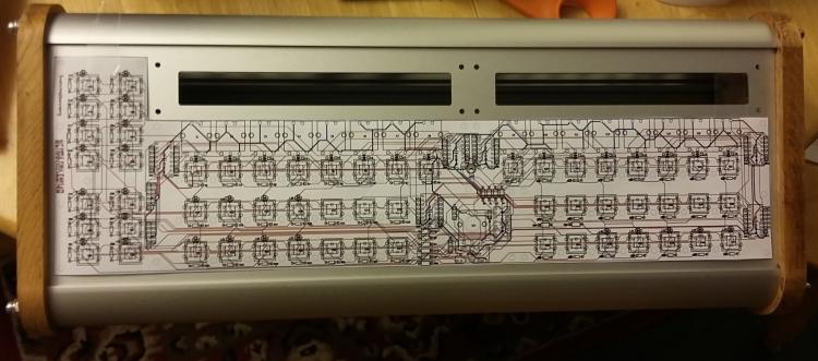
It lines up well now with Julian's case. There was a bit of an angle on the camera causing some of the pictures not to look 100% square but it lines up perfectly in person. I checked part sizing as well and it all looks good. Switches line up, encoders line up and ic sockets are spot on. The smaller switches line up as well. I did not have any of the larger square switches to test out. The ones with the switch caps that the case is cut for line up perfect. I have some large double sided copper clad if you post the artwork for the top and bottom I can make a test print. It might take me quite a while to get it done though I am short on spare time to do all the drilling in the shop for at least a week or two. Bathroom renovation under way currently eating up all my spare time... Might be faster to have them run at the fab house. I traced through the board a bit and did not come up with any errors. I have not seen anyone asking about it on the Seq 4 designs but with the sid cs the lights flicker on startup. latigrid-on had an elegant RC delay solution that he posted in this topic: http://midibox.org/forums/topic/20493-leds-light-up-when-switching-on-midibox/#comment-178481 Thoughts?

-
I printed the PDF to 11x17 will test it for fit tonight.
-
You should be able to print to a custom page. Just get some 11x17 paper and cut it 8.5 wide. set the custom paper as 8.5x17 and you have plenty of space to print it out. I have access to a large format printer and have printed what you have posted so far on 11x17 and it is scalled 10 to 15% smaller than it should be for some reason.
-
SwinSID - a pin compatible alternative to the SID chip
gerald.wert replied to TheFumigator's topic in MIDIbox SID
I recently built one of these with some 8515. Works great. Was curious why the output filter is a 1K resistor with a 1uF cap. That seems like a high pole for the high pass filter at about 160Hz. Would a 100k resistor be a better selection to set the pole at 16 Hz or is there something I am missing as a reason to set it higher? I am currently running with a TDA1543 if I wanted to use one of the PCM17xx does anyone know where to source the second clock from for SCKI? Also would it sound better if the opamp filter was added as on the data sheet vs the passive? It would seem the design decision was for simplicity and not having to source a differential supply. Also saw this fun tube output idea for the TDA as the output. Not sure I want the 330v in my audio gear though but I may at least bread board it out to hear it. http://www.lampizator.eu/lampizator/REFERENCES/AH%20DAC/AHDAC.html Also is there any opinion of the 88pa version without the DAC versus the 8515 with the dac? It can run a bit higher clock and I have read that it sounds a bit better as it is running a higher sample rate. I saw that some equipment was having issues with the output but no real details on the issue. It can be sized down a bit more so that may be nice as my midi box is in a c64 case and space is at a premium in there. -
Thanks Latigrid. I have not built the i2c pcb so was not sure if addressing could be altered or if the addressing was locked.
-
I can not see what is being used in the box for midi io. If the iic modules are being used it could be possible that the pic chips are in the wrong order. Each one should have its own id and that could be causing your numbering/assignment trouble.
-
Do you have a core32? I have had good luck using one with the midi2x2 firmware when I am having issues with my other midi adapters.
-
I was comparing to this version: http://midibox.org/forums/topic/10998-mb-seq-v3v4-control-surface-pcb-and-matching-case/?do=findComment&comment=93863 It is rotated on the newer single board version on the wiki. Guess it really does not matter much it is not functional. Not sure the scale matters unless the board manufacturer will hit you with an additional setup fee if it is off. That is if they check for that. SVG should print accurately though. I might just be my setup. If the scaling error is in the gerber though that would be bad. Does it print scaled properly on your end?
-
L31 is placed rotated 180 from all other leds on the board. It would not keep it from working but it would be good to rotate it for consistency. The SVG also seems to be off scale by about 5% or so. If I set the scale to 100% and print to 11x17 it is small. That may be something on my end I am just printing from chrome. Can not get to my inscape machine right now. I would route the red trace on the inside of the top right mounting hole and give the mounting hole plenty of clearance that way you can use washers if you want when you mount for strain relief. It is ground so not sure it matters it just sticks out to me. I have not seen anything else yet but will look some more as I have time.
-
I have an empty case from julianf so should be able to print a PDF of the board and check if it will fit and line up in there as well.
-
I have made a few of my own small boards and can take a look at it.
-
Use http://www.midibox.org/dokuwiki/doku.php?id=default_encoder_assignments to map the menu encoder connections. and http://www.midibox.org/dokuwiki/lib/exe/fetch.php?media=mb-6582:mb-6582_cs_din_wiring.pdf to map the buttons you need. The buttons are in a matrix you just need the buttons and a diode each. No matrix on the encoders. You would just jump off the headers on the main board to your temporary cs board. All you need for buttons are the menu button and the 5 select buttons. Everything else you can access from the software.
-
I agree the matias switches are great quality. I have sourced a few samples of the above switches and a few others looking for something decent and like you said I have not found anything unless I am going to spend well over $3 a switch led and cap once you figure every thing in. Hope I did not side track the discussion too much. I have been watching this project and am interested in it when you are ready to go live with it.
-
borfo, The buttons you list say they are locking/latching buttons. I do not think they will work right for a seq build. They lock/latch on when you press them and switch off on a second press. All the button types I have seen used in Seq4 builds are momentary contact buttons that are only on when pressed or if you hold them down. They would make a great lighted power button though. I was considering buttons like this http://www.ebay.com/itm/182283287201?_trksid=p2060353.m2749.l2649&var=484821440994&ssPageName=STRK%3AMEBIDX%3AIT for a seq build like you mention. I was thinking of ways to shrink the seq front panel to be able to fit it into a c64 case and still have all the buttons and lights. lighted buttons would allow for that. A dual color or a rgb would be even be nicer as than I could color code things.
-
Looks easy enough to get going. I don't have a problem with a simple fix.
-
You may be able to significantly reduce the number of encoders an buttons you have if you color code them. Might help out with your work flow as well, by seeing what is active by what color is lit at any time. The beat step pro has a really good layout in this regard, might be worth a look while you are in planning mode still. Transparent shaft encoders with a rgb led under them would be pretty awesome for that with the clear knobs. RGB led rings on the encoders would do the same but would use a lot more parts and may be redundant if you are planning to put the values on the lcds. Behringer made led rings with just single color regular leds on their BCR2000 and BCF2000 no LCD. Check out their xTouch stuff too for some ideas.
-
http://midibox.org/forums/topic/20087-lpc1769-rev-d-board-how-to-load-bootloader/ Here is the bit to get it going and where to take off for the network rx/tx lights if you need them. You can not use the old instructions and programmer since they changed the programmer you need to use the newer version. Once you have the boot loader on there you just load you application as normal from mios studio. You should be totally fine if you are making your own board just be sure to put the pins in the right place. I think they changed pin spacing on rev C. So get the latest model for your cad program. You do not have to cut the programmer off anymore either there is a jumper to enable it on the new board. Yes the stm core has the M4 too. You get a lot more processor over the M3. They are only $21 on digikey now. Super affordable. I picked one up on ebay for $19 including shipping recently. Might be worth looking at. I know I would spend a lot more than that in my time trying to port an application. My thriftiness also wants to use something I already have so is a struggle for me. :) They are twice the size of the lpc though and that is including the programmer on the LPC the LPC is 1/3 the size of the STM if you take the programmer off. Just if space is a consideration. With the audio jack and buttons it is taller too. The node MCU is definitely interesting. I also like the getchip chip computers. I picked up a few for wireless print servers. they have Bluetooth, wifi, lipo charger, audio, video, good size flash would be perfect for anything you wanted mobile with network access to run from a battery. Your welcome and good luck with your project! The speak jet always looked interesting to me but I never had the time to build one. I have a spare LPC board here so if you do make a layout let me know maybe I can put it to use. Was thinking about using it with the TIA video adapter but have not gotten to it yet. Gerald