

TK.
-
Posts
15,248 -
Joined
Content Type
Profiles
Forums
Blogs
Gallery
Everything posted by TK.
-
From the album: TK: MBSEQ Aluminium Case
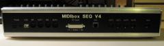
Another view of the backpanel - I consider to swap the positions of Ethernet socket and SD Card/AOUT Extension slot, since internally the SD Card socket clashes with the socket of a LCD -
From the album: TK: MBSEQ Aluminium Case
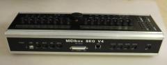
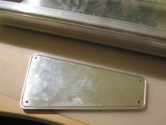
Finally a closed case - hurray! Note that this backpanel has some layout errors as explained in the forum thread. E.g. due to slightly wrong dimensions, the case isn't completely closed (upper screws don't match with the screw threads) -
From the album: TK: MBSEQ Aluminium Case
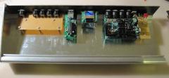
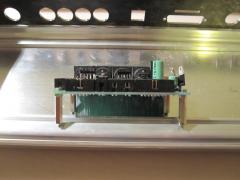
After all modules have been mounted... -

From the album: TK: MBSEQ Aluminium Case
3mm holes have been drilled for all modules. The holes have been deburred with a 5mm drill -
From the album: TK: MBSEQ Aluminium Case
I glued 5mm standoffs to the front mounting holes of the MBHP_ETH module - no screws can be used, but the construction seems to be stable -
From the album: TK: MBSEQ Aluminium Case
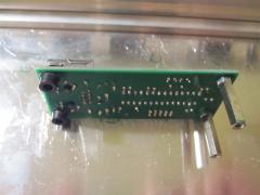
Preparing the core module for mounting -
From the album: TK: MBSEQ Aluminium Case
Due to special request: this picture shows the slots of the sidepanel -
Unfortunately DIN7 sockets are not available at Reichelt anymore, therefore I've to change the spec: use a 8pin socket Reichelt Order numbers: MABP 8SN for the print socket, MAS 80SN for the plug Best Regards, Thorsten.
-
MIDIbox Link won't work for the MBLC protocol. As already mentioned, the protocol requires individual MIDI IN and OUT ports. Thats predefined by all DAWs which support it... This means, that you have to use a MIDI Interface with at least 3 MIDI INs and OUTs (such as GM5x5x5, it gives you two free MIDI IOs in addition) When you are using the search function you will find a lot of threads around MIDIbox LC topics (sometimes the shortcut MBLC is used) Best Regards, Thorsten.
-
The sidepanels have slots as well. yes I got it as a .pdf file, and I don't know if the original format was a DXF file - is a DXF really required? (I don't want to bother Heidenreich too often with such special requests...) Best Regards, Thorsten.
-
Here are the exact measures: http://www.ucapps.de/midibox_seq/mbseq_case_measures.pdf Best Regards, Thorsten.
-
Could you please explain what you mean with "active leg"? And why do you mention a "ground leg"? No leg should be connected to ground... Proposal: use the beeper of your multimeter to check your button. You need two contacts of this button. The contacts should be closed (-> BEEEP) when button is pressed, and opened (-> no beep) when button is not pressed Connect one contact to the DIN module (together with the contacts of the other 3 buttons), and one contact to the anode of the diode. Best Regards, Thorsten.
-
By connecting ground to a row button, all four button functions will be activated at once... Only the periodic scan realized via DOUT pins ensures that a single button press can be detected. However, on the other hand: if it worked this way, it means that your buttons are (or were) connected correctly, and that the issue is between buttons and DOUT pins. Yes, of course! This is the error! Best Regards, Thorsten.
-
Hi Igor, I can confirm that this is a firmware bug (assignment value is masked incorrectly) Sometimes 1..4 will be displayed, sometimes 5..8 - but the actual assignment will always be 1..4 It will be fixed in the upcoming version. If you mean dependencies between HH, Snare and Cymbal sound: yes, they are using the same oscillator, therefore they influence each other. If you mean another drum instrument: could you please attach a .mp3 sample of this random sound? Best Regards, Thorsten.
-
In addition the "GSA" (Gate Stays Active) flag should be set in the OSC menu, otherwise you won't hear any sound at the release phase of the envelope Best Regards, Thorsten.
-
It should work if you change it to a 17" panel (resp. if you reduce the sides which are used to mount the panel into a 19" rack) Currently I cannot confirm your changes as I'm waiting for input from Heidenreich. Background: I made some errors with my backpanel. The "rectangle in rectangle" wasn't specified correctly, so that only 1 mm of the border has been milled away instead of 2 mm. As a result it wasn't possible to plug the panel into the slots. Fortunately I was able to fix this with a file... Thereafter I noticed a misadjustment of the panel by ca. 1 mm, which doesn't look so nice. My tools are not good enough to measure dimensions with such an accuracy. And maybe it's better to have a frame of 1.5 mm at top/bottom (but not left/right side) instead of 1 mm... Therefore I have to redesign the layout based on the exact specs from Heidenreich, and probably should order a second prototype before publishing the .fpd file to ensure that you won't do the same errors. I also want to say: I'm the wrong person to ask for confirmation - somebody with more experience should do this! ;) The good news: mounting of internals is almost finished, pictures soon! Best Regards, Thorsten.
-
The current situation is still unclear - could you please answer to my questions? Best Regards, Thorsten.
-
Hi, since the Logic Control Protocol requires individual MIDI ports for each set of 8 faders, and since the core module can only control 8 motorfaders anyhow: 24/8 = 3 Best Regards, Thorsten.
-
It's normal that you won't measure 5V at an DOUT pin which is used to control a LED and/or button matrix with a common multimeter, as the output patterns are changing with high frequency. And even worse: if somebody would tell you the voltages that he measures at J4 with his multimeter, you would measure different values with your multimeter - because multimeters are just not made to test waveforms... By reading this thread is hard to understand the current state - are the buttons working? (does the menu page change when a button is pressed?) - are the LEDs working? Is only a single LED enabled (thats the expected behaviour) or are multiple LEDs enabled (this would indicate a wiring error). Sometimes you are asking if the schematics are correct, or you are asking questions (such as "ground connection?" or "cathodes before resistors?") which are definitely documented in the schematic (to answer these questions: no and yes) I can confirm that the schematics are correct! http://www.ucapps.de/midibox_fm/mbfm_din_default.pdf http://www.ucapps.de/midibox_fm/mbfm_dout_default.pdf Best Regards, Thorsten.
-
This feature is already provided by MBSEQ V4 (press SELECT button in Manual Trigger menu), but there is no free memory in the PIC based V3 firmware to add it as well (and I wouldn't be able to test it anyhow...) Best Regards, Thorsten.
-
The values of the original SID spec have rounding errors (consider that the spec has been written around 1982...) E.g., take 274 for C0 as an example. Multiplied by 12th root of 2 (=1.05946) makes 290.293, rounded: 290 and not 291 Thats btw. one of the reasons why MBSID sounds better compared to other SID synths ;) It's your own decision if you want to re-calculate the lower frequency values as well. It isn't so much effort... Best Regards, Thorsten.
-

AIN would also accept 100kOhm poti inst. of 10kOhm?
TK. replied to fairplay's topic in Parts Questions
probably nobody tried this with a stm32 before. there is the danger for even more jitter due to the reduced voltage range (0..3,3v)... but stm32 has much more internal sram than a pic, so that it would be a no brainer to add individual resolution parameters for all AIN inputs. however, i will try a 100k pot and report results once i'm back home (next week, so early enough before october ;) best regards, thorsten. -
AIN would also accept 100kOhm poti inst. of 10kOhm?
TK. replied to fairplay's topic in Parts Questions
according to the pic datasheet the input resistance shouldn't be higher than 10k, on the other hand i know that people used 100k joysticks before and didn't complain. it could happen that sometimes (e.g. depending on ambient conditions like temperature, etc.) CC values will start to jitter, but mostly this doesn't really hurt (e.g. as long as your application doesn't start to record automation data on value changes). adding a 11k resistor in parallel won't help (leads to nonlinear curve), reducing resolution would help to avoid any jitter, but i would propose to start with the default resolution. best regards, thorsten. -
Change modify DIN table on MBFM for button assignment
TK. replied to Echopraxia's topic in MIDIbox FM
this isn't possible, as the button handler is tailored around the matrix handling. you would have to implement dedicated button handlers for each button function, but there isn't enough free memory in the firmware. it's better and much easier to get your matrix issue fixed at hardware level. best regards, thorsten. p.s.: what do you mean with "can't get the interrupt service routine working"? did you already modify the firmware? if yes: why and where? -
A nice idea - I haven't considered such possibilities yet since MIOS8 was always restricted on RAM limitations. Note that the same concept can be used to drive a LED matrix - e.g. set DOUT_NUM_BUFPAGES to 8 and output (1 << counter) to an additional DOUT register. If you are working on an extension on MIOS32, you could consider this usecase as well. Best Regards, Thorsten.