

Duggle
-
Posts
992 -
Joined
-
Last visited
-
Days Won
5
Content Type
Profiles
Forums
Blogs
Gallery
Everything posted by Duggle
-
I'm working with mixer map #1 and #2 at the moment. I'm finding when I go menu+GP1 ("mixer") the mixer map that comes up is #65 or #73. I then have to use Select to scroll to the mixer map I'm using. Is this avoidable? (I'd prefer if it stayed on recently used #'s)
-
Hi Marxon, thanks for your input. I thought I had a viable explanation for how the 256 patterns were organised: 4*64=256 On the Grp. Save Pattern page the "to Target" can have values 1:A1 to 1:H8 to 2:A1 to 2:H8 etc, to 4:H8 That would be the 256 patterns? Now in the "Pattern Screen" part of the manual it says there is lowercase designators a..h providing another 64 patterns, though I can't activate them by pressing the left GP buttons twice. It also talks about accessing Bankstick which seems a bit old. Still not clear.... I think you can copy (the pattern contents) material from one track group to another?
-
Is the CC's data sent by SEQ under any circumstances? (or just received) I'm referring to what's documented in "\mios32\trunk\apps\sequencers\midibox_seq_v4\doc\mbseqv4_cc_implementation.txt" I was thinking about if it were possible to update a control surface with the current state.
-
I've had my SEQV4 up and running for some months now, and I realise my usage of it is now being limited through an incomplete understanding: A pattern consists of 4 parallel tracks (1,2,3,4). Each track has it's own properties including port, channel, length, direction, resolution, etc. The pattern is known by a designator A1..A8, through to H1..H8 ( 64 patterns) There are 4 track Groups. Each group has it's own set of patterns (A1..H8) This gives rise to 4*64 patterns stored in (the 4 bank files of) a session? I'll pause here, please pull me up if I've stated anything wrong...
-
Thanks TK. The sync is working well now. I will experiment with it like this....
-
Thanks TK. SEQ_CORE_Tick is nearly 700 lines, I'll have a good look at it. In the meantime, is there a small change possible to the Slave sync mode where the transport controls behave as if master? (i.e Start and Stop (buttons) do just that, and send out start and stop messages respectively.)
-
Ahh, documented in the manual already, thanks TK! :smile:
-
Well, I'm finding OpenOffice Draw is working perfectly for me. Can define objects (primitive objects grouped) and drag them around the sheet, the curvy arrows stay connected, and can have sticky labels. Having the diagram easily available on the desktop really helps too, especially if I change something, add or reorganise the gear.
-
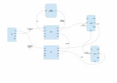
From the album: Duggle
-
Great, is there an unlock command?
-
Thanks TK, so far so good! I am now able to start and stop the RC-50 on the fly under SEQ control. As I may have mentioned, the RC-50 midi implementation is extremely lame. I'm not being unkind, I think it is the case that it was deliberately engineered to avoid external automation (maybe to avoid the possible wearing out of flash memories that could stem from this, I dont know). Anyhow I'm using the footswitch inputs to increase the amount of control. I have J5.A1 driving an optocoupler that is activating a footswitch that is set to execute start/stop. I'm executing a Program Change output with a mixermap encoder. Question:what is the best way to program a PrgChange message at a more or less precise (arbitrary) moment? I'm hoping we can continue the experiment. I agree there is a bit more testing before we could say this is actually worthwhile. Could we change it so that the transport controls more like the normal Master Mode. ATM it is not actually outputing start/stop. I would prefer to turn off midi clock output back to the RC-50 (but still have start/stop transmitted). If it's not possible to to have clock output turned off and still have start/stop output, then thats o.k. I'll have clock output turned on to this port.
-
I was interested to read the WIKI article by Ilmenator on his BPM,Step#, and TPD combined PCB. I'd like to add some of these elements to my own seq. The BPM and Step# display hw settings are in the config file MBSEQ_HW.V4 looks straight forward. The Track Position Display section has config settings for 8x8 single LED. What is the state of the 16x8 Duo TPD from the software support aspect? Is it likely to be merged with the main firmware?
-
The naming feature works nicely! Anything that clarifies, and helps one be organised, is good! (low priority: the cursor position is visible but a bit unclear, would an inverse cursor be possible? The auto advance of the cursor is good but the flashing asterisk is very faint on my LCDs ) Anyhow, thanks TK!
-
It sounds like the button is wired o.k What about the core to DIN PCB connections? With the power off and the multimeter set to continuity, check each of the 3 lines: clock, data, RC between the pads of J8 and the pins of the first shift register.
-
I was wondering about the feasibility of a 4th clock mode. Its like the BPM Slave mode except that the SEQ will ignore incoming Start/Stop/Continue. Its like being a system master except it syncs to external clock. The change I'd also like to use with this (maybe part of the proposed 4th clock mode) is that when stop button is hit, a Stop is transmitted and the sequencer stops ( the same as it currently does when it receives a Stop externally) rather than the state where the play and stop LED flash alternately. Perhaps this mode would be called Master Clock Slave (or something)? If the proposed mode is not available through the menu but a line in the config then I'd be just as happy. My usecase is where the SEQ is used in tandem with a Boss RC-50 Loop Station. The RC-50 works best when it is clock master. The SEQ is really in control though. I wish to change patch on the RC-50 (opens up hugely more arrangemental possibilities). To change patch on the fly, I'll need to stop (via external trigger) just before the end of a measure and restart the RC-50 (also via external trigger) at the beginning of the next measure. Where this comes unstuck is that the RC-50 outputs a Start/Stop/Continue merged with the clock that unfortunately the SEQ responds to.
-
It depends on the load that the output is driving. 1k to 10k sounds more reasonable for high impedance inputs than 220R. I am about to use the triggers (4) to drive the footpedal inputs of an RC-50 Loop Station. To do this I'll have the outputs in pushpull (LPC17 Core) drive the LED of opto-isolators via 220R in series. The opto's will provide isolation to remove ground loops between SEQ and Looper.
-
The pins are 5V tolerant, so you could have a pullup to 5V and output 0..5V logic levels.
-
That's an interesting idea, it would have to be better than Altium in terms of dragging connected components around the sheet. IIRC it is.Anyhow, I'll roll with OO for now. The curvy arrows are cool. The grouping of graphical features and the snapping to arbitary glue points will allow me to define the items of studio gear (basically only one instance of each).
-
Openoffice Draw seems to fit the bill quite well. You can add "gluepoints" to objects at will. Connectors (curved arrows, etc.) stick to them so that when a block is moved the arrows follow. Using "group", extra text labels can be added near the gluepoints. In this way it is possible to have, for example a box labelled "SEQV4" with 4 labeled midi in points, 4 midi out points, all with arrows connecting to other similarly drawn items, and drag them around to while editing the diagram. Nice.
-
The main signal that is an issue is the SCLK. The idea behind this is to match the resistor value with the impedance of the transmission line. The actual line impedance is a little hard to determine (an estimate can be made using an inductance/capacitance meter) so you could experiment tweaking (try changing up and down) the value of the resistor on the SCLK line. At a certain point the serial I/O will cease functioning completely and at the other extreme you'll see the spurious results you've seen without any termination resistor(s). Somewhere in between things will work. I just checked mine, and it is 100R. If 110R is not perfect, then try 3x 220R in parallel(~=75R) or 2x220R (in parallel) in parallel with 440R (in series, 220+220) .
-
Ok, I think I have the general idea. Try this:
-
Please swap the boards in the chain. You may find that a very similar problem is always on the 4th PCB connected. If so let us know as there is an easy fix for this (signal integrity issue).
-
So my rig has at least 3 devices with up to 4 UART MIDI I/O's each, and 4 USB MIDI ports each. Very powerful, but easy to get confused. Some time ago I started using Google Drawing on a Google Drive folder to diagram the interconnections. (So I can refer to the diagram anywhere..) An example is here: The Google drawing tool is not really up to the task. Ideally you want to be able to drag the objects and have the line connections stay. The objects need to have multiple connection points (say at least 8 for 4 port SEQ) If you can't label the connection points (e.g Midi In3) then you need to be able to label the arrows between gear. Do you know of a free, cross platform drawing tool that meets the spec? (Just tried Dia which seems to fail criterion 2. and 3.) Thanks.
-
I'm now in a multi USB MIDI Port wonderland! :smile:
-
Patience is a virtue! Btw: I've been fairly active over most of the past 10 or so years, I too am giddy with excitement! :frantics: