ilmenator
-
Posts
2,305 -
Joined
-
Last visited
-
Days Won
37
Content Type
Profiles
Forums
Blogs
Gallery
Everything posted by ilmenator
-
Well, the obvious would be: get another encoder!
-
Guys, make sure you agree on shipping declaration and insurance - Norway is not in the EU, hence shipping to the EU will probably involve customs, if value is declared correctly.
-
///////////////////////////////////////////////////////////////////////////// // This function is called by MIOS when an button has been toggled // pin_value is 1 when button released, and 0 when button pressed ///////////////////////////////////////////////////////////////////////////// void DIN_NotifyToggle(unsigned char pin, unsigned char pin_value) __wparam { MIOS_MIDI_TxBufferPut(0x90); // Note Event at channel #1 MIOS_MIDI_TxBufferPut(pin+offset); // just forward the pin number (0..127) MIOS_MIDI_TxBufferPut(pin_value ? 0x00 : 0x7f); // Velocity = 0x7f when // button pressed, else 0x00 } in which offset is the transposition you want to apply. E.g., if you want your notes to be played one octave higher, then offset = 12. Hope that helps, ilmenator
-
So I went to download the PCM Card Workshop files, but could not get the program to run on WIN 7. As they have included a demo file supposed to be ready to use, I took a look at it with a hex editor and noticed that the header is somewhat different from the WSC cards made for the "regular" Wavestations. It seems as if the WS SR cards used a 16bit wide encoding for header and waveform names, whereas the older WS cards use 8bit. Anyways, I put the demo file on an SD card and loaded it into the MIDIbox SCE. The loading went fine, and the SCE displays the card's name (taken from its header) somewhat correctly, but the Wavestation does not see the waveforms. It complains that there is *NO CARD*. This makes me conclude that the PCM Card Workshop program may not be the right tool to create new PCM cards for the original Wavestations (and EX and A/D models). For this, one would still need the Zadok SAM1. Or reverse-engineer the original format and come up with a new software tool. Best regards, ilmenator
-
The shipping costs to Norway are almost prohibitive. If one of the MIDIboxers from Sydney would be interested enough... Of course it would be possible to reverse-engineer the PCM format. It's only a matter of finding someone crazy enough to invest a decent amount of time into something that is obsolete :whistle: . I may already seem like such a person, and I probably am, but right now I have to get the revised prototype board made and do the documentation for what is there. And it's summer here, and everybody knows that such activities are better suited for winter time... Actually, I think that there was quite a decent description of the format on the PCM Card Workshop site which is referenced in one of the postings above. But that was the 01/W and Wavestation SR format. The question is whether the "regular" WS and M1 share that, or if they are different (apart from the different form factor of the storage cards). It would be easier editing the samples on the PC and putting them together to form a "set". You can do that on a microcontroller and a 2x24 display, but I can tell you it's no fun - my Zadok SAM1 offers this. Right now, the SCE is not meant to be capable of creating your own PCM cards - that's a different beast, and may be something for the future. It can merely extract data from existing cards, store it on SD card, and read it back from there to present it to the WS as if the original card was there. The advantage of this over using actual PCM cards is that you only need the data, not the actual physical card.
-
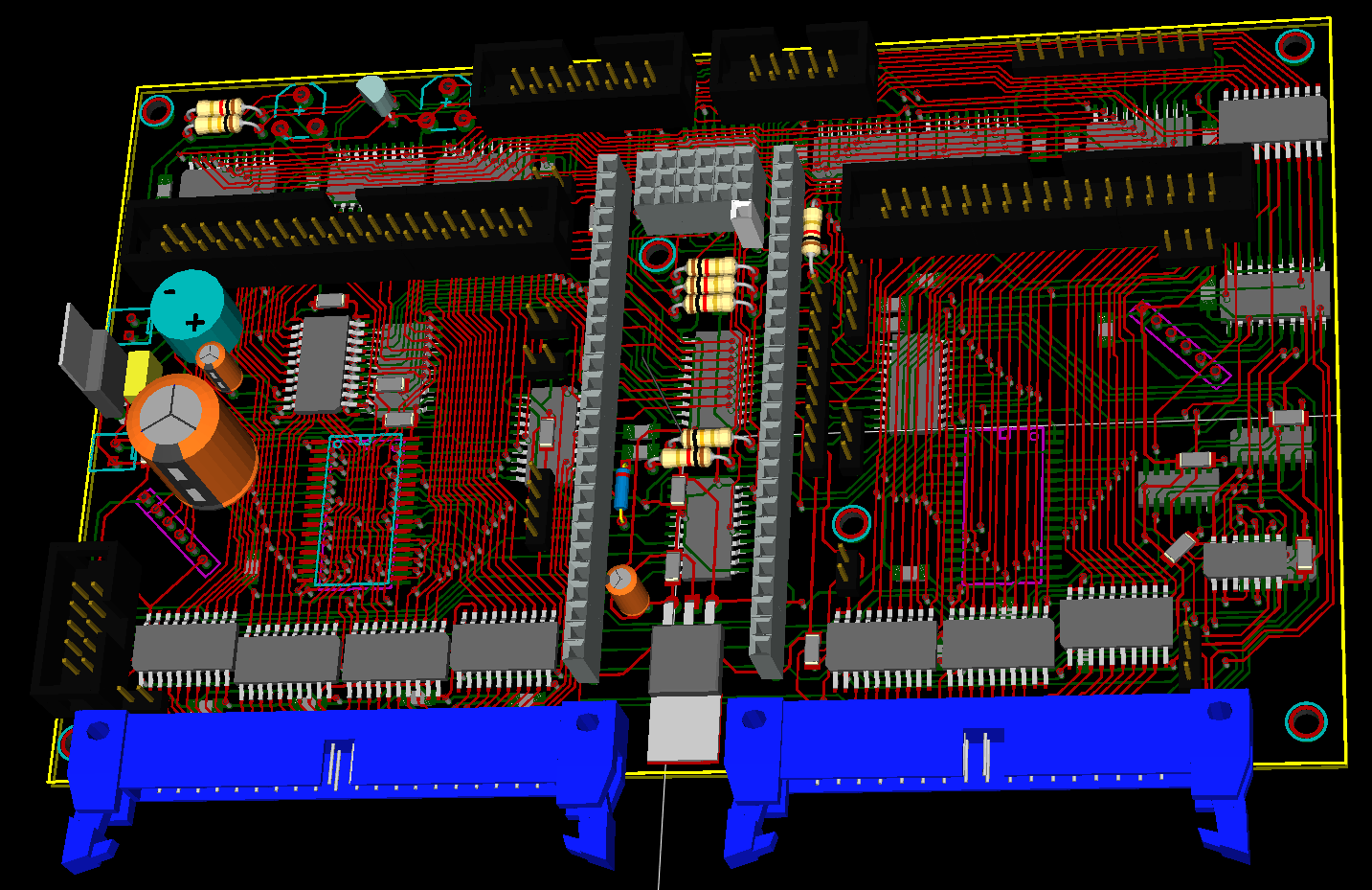
Thanks nebula! I remember being on the majordomo list as well - so we've known each other for longer than MIDIbox... :tongue: The shield board will not feature the SD card socket, but a DIL socket to run a cable to a daughter board, just like on the LPC17-based core. This is because I imagine people to want different configurations of / cases for the SCE. And then it is not clear what the best position for the SD slot would be. On top of that, there is simply no more space on the board, and I do not want it to become larger - look at the KiCAD rendering in one of my earlier posts. As it is now, it has the "Euroformat", i.e. it is 100x160mm, which is pretty much a standard size. Easy to ship, easy to find a case for. Ahh, by the way, it was exactly my intention to place this thing below the A/D in the rack. Maybe abuse an old Korg M3R? :angel:
-
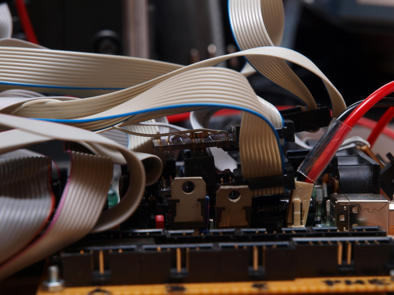
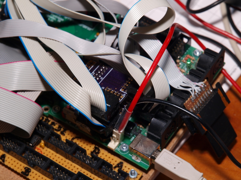
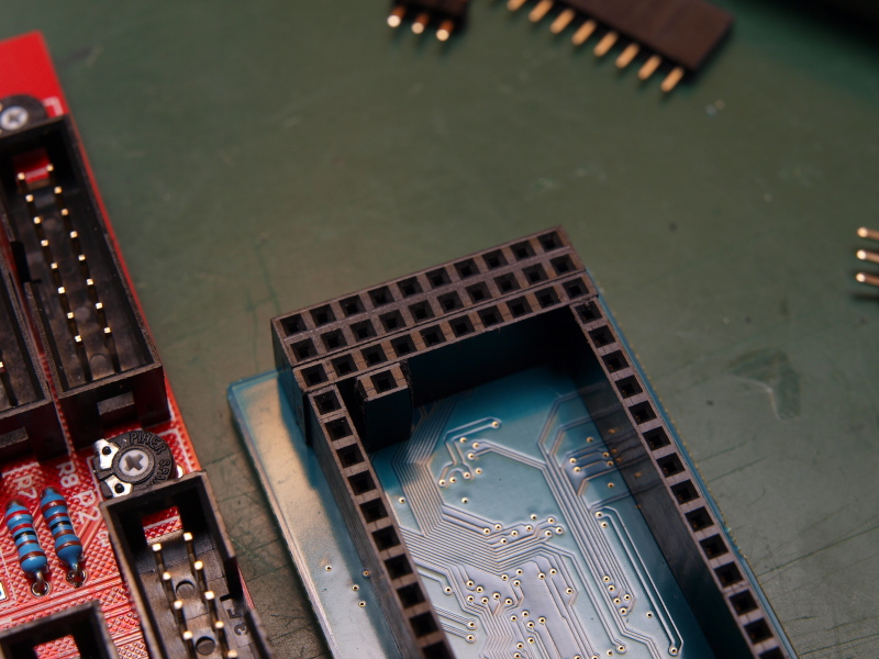
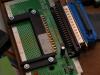
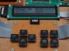
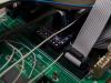
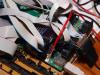
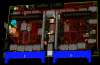
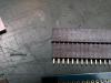
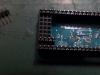
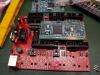
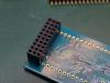
Here are a few more pictures of the ugly prototype and development board. The transition from PIC core to the STM32 core on the way required a number of stack boards, e.g. for voltage level shift on the buses, that I had not anticipated when I had the protoboard made... As I said above, the next generation board will carry the LPCXPRESSO board - and will be much cleaner then. Here is the user interface, basically a CURSOR cross, ENTER and CANCEL buttons, as well as two dedicated FUNCTION buttons. Here is the card reader for the PROG (RAM/ROM) cards - taken from an old mini computer device. As you can see, I had to use a lot of SMD devices - on both sides of the PCB. The board would have become too big using only through-hole components. Also, some of the components in the original design were only available as surface mounted devices. But the SMD pitch used is still rather DIY friendly :smile: . Best regards, ilmenator

-
Been there, done that... It seems that the relevant BB code extension is not installed for this forum.
-
Well, on the SCE it is straight forward: just use a ribbon cable to connect to a small (PROG/PCM) card-size PCB that provides the contact pads. On the SAM1 it is more complicated, I assume because of the line drivers / impedance matching. Their cable is about 80cm. I have not tried what my max. cable length would be. Sure, this sounds very good! If you get it to run, you could create a 512kB (or smaller) binary and I'll try to load it and see what the A/D can do with it. Then we'll know if the PCM data format is the same or different :twitch: Best, ilmenator
-
I had this idea in the back of my mind for a couple of years now. I started off developing this about six years ago, on the "old" core8. In the beginning I tried to implement CF card access but somehow never got it to work properly. Along the way I buried the project and resurrected it a couple of times. I do not own an SR, but I have a A/D and an EX. The SR is probably not a prime candidate for the SCE, as it has more sounds on board already. I do not have any documentation about its PCM sound format. I would suspect that it is rather the form factor of the cards that makes the difference. Back in the day this was probably necessary to accommodate more memory in the cards, as the original WS and M-series PCM cards "only" hold 512k of waveform data. Also, I doubt that there is more PCM data for the 01/W series than for the M1. I've been collecting the M1 PCM cards, and there were quite a few of them published. Most of them (well, most of the waveforms stored on them) work with the WS. If there was a real demand for conversion (and documentation was available), this could be handled by software on a PC. You would then save the converted set of data to an SD card and have it read by the SCE. Yes, I saw that offer as well. BUT, it came without power supply and without the connecting cable to the WS. The latter is a problem, as the SAM1 uses a PCB card with some electronics buried under a block of resin as connector to the synth's PCM slot. I guess no one knows what is inside this but Zadok. I have one of those units myself, but I would not want to ruin mine trying to scrape the resin... But of course, everybody with a SAM1 could create PCM banks that he could provide to those using a MIDIbox SCE. Maybe that is incentive to some. I always found it quite strange to know that I would probably be the only one who could use the banks I created on the SAM1. In that sense, the SCE is very different from the SAM1: it cannot (yet?) be used to create PCM banks yourself, it can only make "backups" of existing cards. (Or, it can be attached to a SAM1 to read PCM data coming from there.) I guess I should sell my PCM cards now, before everybody owns an SCE :devil:. I have a copy of the "PCM card workshop" somewhere on my hard drive. Just drop me a line if you are interested. The SCE prototype you see in the video is based on the STM32 core. The next PCB proto will carry the LPCXPRESSO as a shield. The PCB design is basically ready, I just have to send it off to the "boardhouse" on the weekend. It's quite a complex board...
-
Well, the topic title says it all... [vimeo]27590820[/vimeo] does not seem to work... Thanks!
-
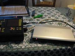
Hi, this is a little teaser for my latest MIDIbox-based project: the MIDIbox SCE. This is a demo of a MIDIbox based DIY project that emulates both PROG- and PCM-cards for the Korg Wavestation line of synthesizers. These units were produced in the early 90s. While they are not exactly collector's items, the RAM-, ROM-, and PCM-cards for these are very sought after today. The DIY project demoed here aims at replacing a RAM/ROM (PROG) and a PCM (waveform) card with a little microcontroller-based circuitry and software that allows to load the corresponding data from SD card. Of course, sound- and waveform-data can also be read from card(s) and saved onto the SD card... This is a proof-of-concept, hence the whole thing looks quite chaotic :-). But it has the main features already and will evolve into a user project with full documentation once I have the next generation prototype boards tested.
-
MIDIbox SID External unit for core+2SID
ilmenator commented on jjonas's gallery image in Members Gallery
 Good job! Fun to see how creative people get with the modular approach of MIDIbox! :D
 -
Thanks :thumbsup:
-
Which tool do you use to insert the comments into the video?
-
Okay, the way you did the routing you could have also used SMD diodes... I was actually refering to the idea of using the diodes to get vertically across the horizontal 8-channel busses. But you've got a clean layout already!
-
LPCXPRESSO socket connection to MBHP_CORE_LPC17 board
ilmenator replied to ilmenator's topic in Tips & Tricks
Is it possible to connect/use the LPCLINK module while the LPCXPRESSO is connected to the base board? -
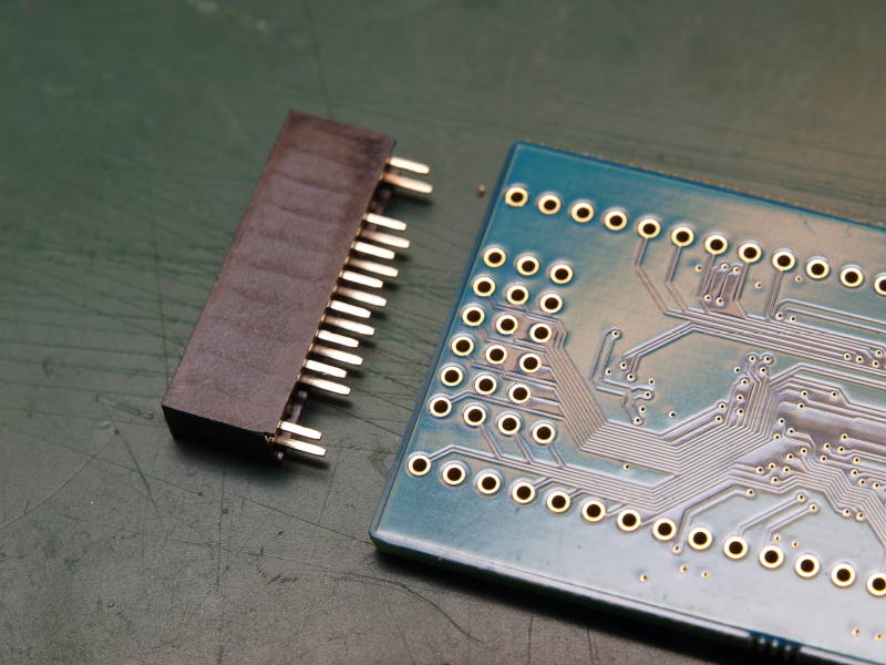
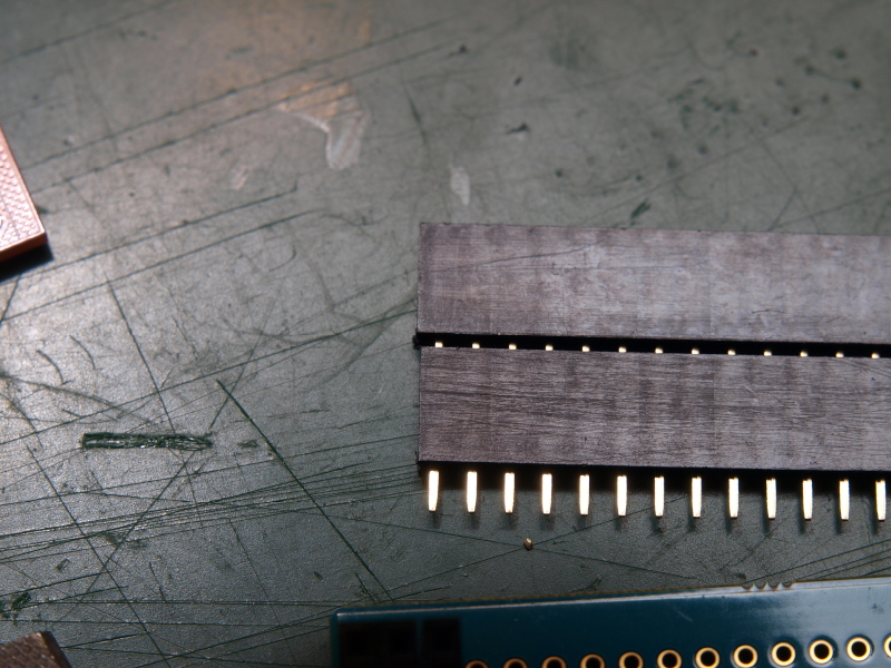
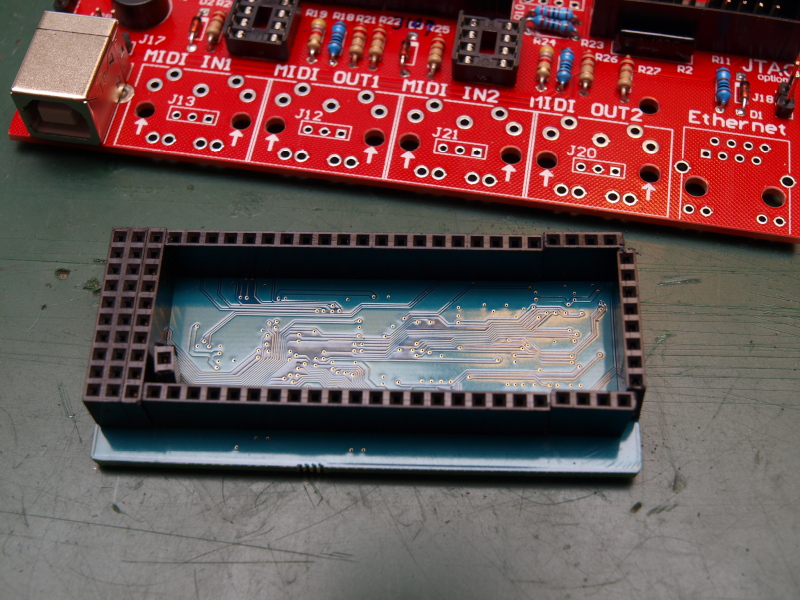
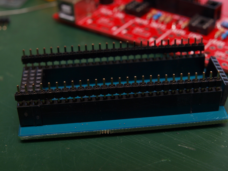
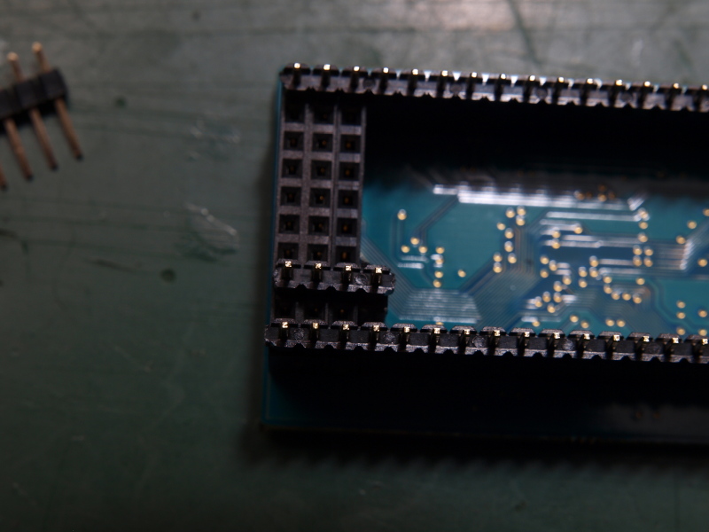
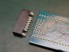
I have just completed my LPCXPRESSO board sitting on top of the new MBHP_CORE_LPC17 base board. As I wanted it to be removable - the LPCXPRESSO will be used on more than one base PCB - I used male and female headers. Female headers are attached to the LPCXPRESSO, just because they are the more expensive ones, and I plan to circulate one LPCXPRESSO board between a number of different LPC17 base boards. It is a little tricky to align the sockets properly, as the female SIL sockets you can get from Reichelt are slightly too long. It means you cannot simply "chain" them, but some material has to be removed from the short side in order to keep the grid. Before soldering the sockets, they should be attached to each other - male into female, so they sit aligned and will be easy to separate again later. Also, I made sure that male and female headers sit perpendicular (horizontal vs. vertical alignment in the fotos) to each other, so that the hole assembly cannot fall apart. Also, this way you make sure that the spacing is correct in both dimensions. Here the two boards have been separated again: you can see how nicely the grid is kept, although it consists of many different (separate) headers. I will use the exact same LPCXPRESSO board again when I prepare the next LPC17 base board! Edit: changed board names to what TK uses here in order to avoid confusion /Edit TK: fixed link


-
I just wanted to know where the soldering pads sit on these switches - I cannot see that from the bird's eye perspective fotos :unsure: . Also, it might make sense to use through-hole diodes for easier two-layer routing... but then you won't have a clean PCB top side.
-
Could you provide a link to the footprints of both buttons and LEDs?
-
KiCAD is an excellent tool - highly recommended, also for complex designs. Back to the original topic: would you need 1 LPC core per BLM module, or is it so that one LPC core can handle the maximum size matrix you have in mind? This, IMHO, would be a clear indicator for whether to include the LPC socket per (modular) board, or keep it separate.
-
Pictures will help!
-
I think you should email him directly with this question... :rolleyes: :whistle:
-
Thanks for sharing! You sure included many mounting holes in there :)
-
Great project, an arpeggiator seems to be very useful with the Matrix! I love the one on my K5k...