ilmenator
-
Posts
2,305 -
Joined
-
Last visited
-
Days Won
37
Content Type
Profiles
Forums
Blogs
Gallery
Everything posted by ilmenator
-
I'd search on eba*. It should not cost you more than US$20 incl. shipping. Best regards, ilmenator
-
A suitable method of storing SID chips?
ilmenator replied to unrise_lyrical's topic in Tips & Tricks
According to Murphy's law someone (you? ;D) will eventually put something near it that actually will bend the pins. Or it falls down from there. Or something else. Don't take any risks, stick it into that special antistatic foam, if you don't have it go buy it! It's a few cents that are well invested money. Best regards, ilmenator PS: stryd was faster again -
They are in the card itself. Best regards, ilmenator
-
looking for suitable 74HC... device(s) for a given truth table
ilmenator replied to ilmenator's topic in Parts Questions
The WS sports 74HC. All cards (PCM and PROG) connect directly to chips that I would deem custom chips, though. Thanks for the compliment :). It's a little difficult to find time for these things between job, family life, new country of residence and all that. The project's on a boost right now (that SD card thing really motivated me, and TK's statements on MIOS support even more so), I'll see if I can keep up the pace this time. Weren't you a fellow WS user? ;D Best regards, ilmenator -
Hi, and welcome! As your first statement is about "affordable price", a word of warning before we start: DIY does not mean "cheap". Especially mechanical components prices for DIY projects can, because of low quantities, become pretty expensive. The worst case I can think of is an 88 key hammer action keyboard. This alone will probably cost you as much or more than a readily built master keyboard from one of the big manufacturers. Therefore it might be a good idea to buy one of those with little controls and only add the controls with a MIDIbox project: additional buttons, faders, LEDs, display etc. Another advantage of this would be that you do not have to worry about a decent case... Best regards, ilmenator
-
In theory probably not, because it can also be addressed linearly, and there is even some PIC assembler code around on the net. But I was not able to get it to run when I tried that seriously last year (could have been my fault, naturally ;)). My advice would be to forget CF. GREAT, GREAT, GREAT! ;D Yikes! Best regards, ilmenator
-
looking for suitable 74HC... device(s) for a given truth table
ilmenator replied to ilmenator's topic in Parts Questions
After doing some searching for (DIY) programmers that can also handle GALs and PLDs on the net I would agree. It turns out that using discrete devices will result in six additional chips for all the "glue logic". The routing will be fun... Another question would be 74HC or 74HCT? Can the outputs drive different amounts of inputs or is this the same for the two families? Best regards, ilmenator -
looking for suitable 74HC... device(s) for a given truth table
ilmenator replied to ilmenator's topic in Parts Questions
Well, in my design the PIC is only used to control the device and to manage the user interface. I have an MBHP based prototype up and running that can read the content of a Wavestation RAM/ROM card into a bankstick and write this back to the WS RAM card. It also displays the card name on the LCD. In the attached PDF you can see the basic structure of the next generation device (PCM section not shown - only contains the sound patch data section). K2 connects to the MBHP core module J15, K3 connects to the Wavestation card slot. K1 is the receptor for Wavestation cards (don't be fooled by the SUB-D37 name tag). IC6 is a 32kx8 SRAM memory, that's exactly the size of a Wavestation RAM/ROM card. The user can select between "Card" access and "SRAM" access - so, the Wavestation either sees the Card or the SRAM. It is extremely important to me that the WS does not see any difference between my device and an ordinary RAM card. The MBHP core module is used to read from K1 (the RAM/ROM sound patch card) and write to SD card, or read from SD card and write to IC6. This is not time critical, because during this procedure the Wavestation will be disconnected from the bus. Disconnecting (and reconnecting) it is also necessary to tell the Wavestation that a "new card" has been inserted into the (Wavestation's) card slot. For some reasons, I WANT this to be an MBHP project.... Also, this project could easily be adapted to support other synths as well - think Roland JV/JD, whatever. Best regards, ilmenator WS_SRAM-card_preliminary.pdf WS_SRAM-card_preliminary.pdf -
looking for suitable 74HC... device(s) for a given truth table
ilmenator replied to ilmenator's topic in Parts Questions
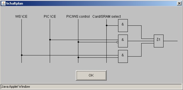
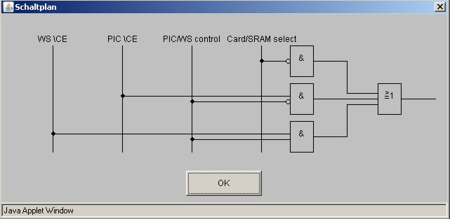
Thanks for these great comments - the Wikipedia link was extremely helpful! Now, what I did come up with is two circuits that synthesize my output signals, see what I attached. The question now is, whether I am better off doing this in discrete logic, in a small PIC or in EEPROM memory, as Thorsten's last suggestion was. I may explain a little more: I've been fiddling around with an idea for more than two years now. It is about a memory extension of my beloved Wavestation synthesizer. So, the PIC-based device should emulate bot a PCM card (this way, all the additional wave forms - key word 'synth & Time Slice' ;D - could be easily accessed) and a RAM card. My main problem was until now the large memory I would need to store the PCM waveforms and the sound patch data - I tried interfacing a CF card to the PIC last summer but for some reasons beyond my understanding that did not work out. As I read between the lines that TK is working on MIDIbox SD, I guess this is nothing I should worry about any more, so I concentrate on the core part of my device. The main "problem" is that both the PIC and the Wavestation will have to access the address and data buses at some given time without influencing each other. I know about techniques to separate the buses using 74HCT245 and FST3245, now I am working on the \CE, \WE and \OE signals. The problem statement above is for the \CE line, the attached pictures (hopefully) make it more clear. As I am talking about bus accesses, this is probably a bit time critical - at least probably more than Wilba's suggestion would permit. Also, I expect at least a bit of interest in this device (e.g. the Synth & Time Slice PCM cardset goes for ridiculous prices on ebay), so it should be DIY friendly - whatever I can do using the MBHP burner would be fine. Best regards, ilmenator

-
Hi all, I'm struggling with implementing the following truth table in hardware; any hints on what (combination of) 74HC... devices could do the trick are greatly appreciated. Here is the problem: [table] [tr][td] Input1 [/td][td] Input2 [/td][td] Input3 [/td][td] Input4 [/td][td] Output1 [/td][td] Output2 [/td][/tr] [tr][td] 0 [/td][td] 0 [/td][td] 0 [/td][td] x [/td][td] 0 [/td][td] 1 [/td][/tr] [tr][td] 0 [/td][td] 0 [/td][td] 1 [/td][td] x [/td][td] 1 [/td][td] 1 [/td][/tr] [tr][td] 0 [/td][td] 1 [/td][td] x [/td][td] 0 [/td][td] 0 [/td][td] 1 [/td][/tr] [tr][td] 0 [/td][td] 1 [/td][td] x [/td][td] 1 [/td][td] 1 [/td][td] 1 [/td][/tr] [tr][td] 1 [/td][td] 0 [/td][td] 0 [/td][td] x [/td][td] 1 [/td][td] 0 [/td][/tr] [tr][td] 1 [/td][td] 0 [/td][td] 1 [/td][td] x [/td][td] 1 [/td][td] 1 [/td][/tr] [tr][td] 1 [/td][td] 1 [/td][td] x [/td][td] 0 [/td][td] 1 [/td][td] 0 [/td][/tr] [tr][td] 1 [/td][td] 1 [/td][td] x [/td][td] 1 [/td][td] 1 [/td][td] 1 [/td][/tr] [/table] I have looked at 74HC151 and HC153, but they only do part of what I need - and then it becomes rather complex... Also, some methodological hints on how to tackle such problems in general would be helpful ??? Thanks, ilmenator
-
Done that. Best regards, ilmenator
-
The WIKI login is the same as the forum login. Best regards, ilmenator
-
Hi TEL0000, welcome to the MIDIbox community! I'm not Durisian, but I think I can help clarifying some points ;). What you mean by pedal is actually a momentary switch / a button ("Fusstaster"). Durisian's pedals are volume or control pedals ("Fusspedal"). Their output is equivalent to a voltage that is sampled at the analog inputs of the MIDIbox core module, whereas you want to use the digital inputs. Therefore, what you have in mind is even easier than what Durisian has done here. I suggest you have a look at the MIDIO128 project. With only minor code modifications you can achieve what you want. Just replace the buttons with the more sturdy version that you call "foot pedal" (this would be "Fusstaster" in German) and there you are. The only important thing is that some kind of contact is closed (or opened) - this is the event that will trigger the MIDI message. I suggest you do some more reading and then come back with more questions if you have! People around here are really helpful if you do your homework well (it's a DIY community, after all) :). Best regards, ilmenator
-
They also arrived here - thanks! Best regards, ilmenator
-
...just leaves me speechless - as so often. This sounds GREAT! Best regards, ilmenator
-
Block read and write are not too different from each other!? Best regards, ilmenator
-
I had a look at the C code of the project - I'm afraid it's a little over my head. The main problem is that there are so many features that I cannot really see where to start. I would not need any kind of file system, a block-wise access to the memory card would be just okay. I guess I need to invest some more time than what I had thought at first :). Also, I am not sure about the code compatibility with the SDCC compiler? Best regards, ilmenator
-
You could also try reed relais, see this thread, very similar to solution A, but no hassle with strange voltages. Best regards, ilmenator
-
Glad you found what you were looking for! :) Best regards, ilmenator
-
reboot, this link has really made my day! I've been looking for ages for some C code to access memory cards. Also, the way of connecting 6 buttons using only one (analog) input is quite clever. Best regards, ilmenator
-
Use the search: go to the "home" tab first and start your search from there. This will cover the whole forum. Use "piston tab" as your search term, if that's what you are looking for. Do the homework yourself! Best regards, ilmenator
-
GM5: Least-cost USB-MIDI Interface Chip for 4.50 EUR
ilmenator replied to TK.'s topic in Bulk Orders
My hesitation is intentional: I want to see what I get first - then I will decide if it is what I need, or whether I am better off doing my own board. As far as I remember, we only started to collect opinions on what type of board would actually be practical for most users? I'd happily go with the generic adapter solution suggested by nILS elsewhere, or even with a board that contained only headers (but no actual MIDI or USB sockets), but I don't know if that is what everybody else needs/wants!? Best regards, ilmenator -
Question regarding LCD display for a Midibox64
ilmenator replied to unrise_lyrical's topic in Parts Questions
Looks OK. Go for it and report back! Best regards, ilmenator -
This one has the T6963C controller which makes the display update rate rather slow if mounted horizontally (see here). Also, I am not sure if the resolution (160 x 128 pixels) is supported by the MIOS driver - you might need to rewrite parts of the driver. On top of that, it looks like this one needs a negative Vee - so, all in all it is not the best display for MIDIboxes unless you really know what you are doing. Best regards, ilmenator
-
Question regarding LCD display for a Midibox64
ilmenator replied to unrise_lyrical's topic in Parts Questions
Good boy, done the homework yourself... ;) Now, you only need to check that the wiring is OK - each pin on the core module should go to the equally named pin on the display. They might be arranged in a different order. Take especially care of the 5V and GND connections so that you don't fry the LCD. That's all. Best regards, ilmenator