ilmenator
-
Posts
2,305 -
Joined
-
Last visited
-
Days Won
37
Content Type
Profiles
Forums
Blogs
Gallery
Everything posted by ilmenator
-
One more picture and the schematic as attachments in this post. In the schematic, K1 connects to the GM5 board. Best regards, ilmenator ilmenator_GM5_05.JPG ilmenator_GM5.pdf ilmenator_GM5_05.JPG ilmenator_GM5.pdf
-
Hi all, I mentioned it elsewhere: I needed a GM5 that does not have all the MIDI connectors next to each other, because that just eats away too much valuable space for me. Also, I wanted status LEDs for each input and output - I find this quite handy for troubleshooting, and during the last ten years my old Thru box (which has a MIDI indicator LED) was the one tool I would take with me all the time - just because of the LEDs. Attached you can find some pictures of what I have come up with. All the easy-to-lay tracks have been done on grid-style board, with the more challenging connections done using a wire-wrap pen. The LEDs are low-current ones (and yes, one is still missing... have to order some more). The original GM5 board sits piggyback on this one and can be removed easily. The whole thing is USB-powered and has a 5m USB cable fixed to the chassis. The MIDI connectors have solder lugs, such that any mechanical stress on the PCB is avoided. They just snap into a rectangular hole in the chassis. The five inputs and outputs sit on separate and different headers to make servicing easy and confusion impossible. ilmenator_GM5_01.JPG ilmenator_GM5_02.JPG ilmenator_GM5_03.JPG ilmenator_GM5_04.JPG ilmenator_GM5_01.JPG ilmenator_GM5_02.JPG ilmenator_GM5_03.JPG ilmenator_GM5_04.JPG
-
Can we get back the old "code" style? Green on black does not really go well with the rest of the traditional forum style (and don't even think of telling me to switch to the new one...) - it's kind of in your face, which is mainly the reason why I also dislike the new style as a whole. Pretty please? Best regards, ilmenator
-
MB-SEQ V3/V4 Control Surface PCB and matching case
ilmenator replied to Wilba's topic in MIDIbox SEQ
:o How many are you planning to build? ;) -
How about MIDIox? I think the functionality you are looking for is there - although you might need a multi-client capable MIDI interface to do everything that you might need. But, for this we have the GM5 :D. Best regards (and welcome back), ilmenator
-
no paint - just bare, shiny aluminium with a white sheet of paper underneath...
-
Well, they are not... they just put in a new mainboard, even for a busted USB connector. This world is crazy. (And sorry for not being of any help in your matter.)
-
Off Topic: Kleines MIDI-Problemchen mit Korg M1
ilmenator replied to Amiga-Falcon's topic in Deutsch
"Active Sensing" ist eine wunderbare Erfindung und kann nicht abgeschaltet werden, weder bei M1 noch Wavestation noch... Im Prinzip ist das ganz praktisch, denn dann musst du keine Tasten drücken um festzustellen, dass die MIDI-Leitung "steht". Alle von dir genannten Programme haben Filter, die eine Anzeige des Active Sensing unterdrücken. Du wirst wohl oder übel mit dem Blinken leben müssen - oder einen MIDIbox Filter dazwischensetzen :). Grüße, ilmenator -
Wuerdest du dann hier vielleicht die Antworten dokumentieren? Fuer den naechsten, der sucht... Danke :)
-
Wouldn't that particular application rather call for the use of a joystick? Could be done with just two analog inputs...
-
Got me :-X. Thanks!
-
Could you add the dimensions of the PCB in metric values to the Wiki page, please? Thanks, ilmenator
-
MIDIboxes in Sound & Recording magazine
ilmenator replied to sneakthief's topic in MIDIbox User Projects
I could not find any info in the Wiki!? ;D -
MIDIBox Mixer - A PGAx311 Audio Mixer
ilmenator replied to lylehaze's topic in MIDIbox User Projects
Strange assumption: you have 4 outputs and want to mix to 5 channels (well, depending on your reproduction setup it's possibly even 6 channels). Where exactly does your math fail? -
...and it all makes perfect sense. Reduce the size of images before you post them here, folks! Why spend so much bandwidth on a blurry image anyway?
-
Da ist ein kleiner Typo drin: es soll heissen PIC18F4685
-
...and also, that you can (should) size down the pictures before posting :) : around 600 pixels in width would be ideal for viewing on smaller screens (or portrait mode screens).
-
GM5: Least-cost USB-MIDI Interface Chip for 4.50 EUR
ilmenator replied to TK.'s topic in Bulk Orders
read the thread -
GM5: Least-cost USB-MIDI Interface Chip for 4.50 EUR
ilmenator replied to TK.'s topic in Bulk Orders
It's the other way round (and in that aspect, the PDF documentation is a bit unclear it seems): don't touch the board if you don't use the EEPROM, cut the "jumpers" if you do use the EEPROM. -
GM5: Least-cost USB-MIDI Interface Chip for 4.50 EUR
ilmenator replied to TK.'s topic in Bulk Orders
I'll put mine in a small as possible plastic case - it will bounce around in the back of a rack. Connectors will be 2x 9pin D-Sub for MIDI and 1x USB. The D-Sub plugs will be soldered to Reichelt MIDI cables cut in half. This is going to be sooo cheap and small! Best regards, ilmenator -
MIDIBox Mixer - A PGAx311 Audio Mixer
ilmenator replied to lylehaze's topic in MIDIbox User Projects
Wow, great work - that looks good! For the WIKI upload, go to the page you want to modify, click "Edit this page" on the bottom left, then an editor view will open. Place the cursor at the position in the text where you want your file/picture to appear. Then click the second button from the right "Add images and other files" (the one with the mountain and sun). A file selection dialog will pop up, scroll to the bottom, select the file to upload from your hard disk, press the "Upload" button - voilá. Now, too, a link to your file has been inserted at the text position where your cursor was located. When you save the modification it is visible for all. Best regards, ilmenator [edit: apparently, moderator status is needed to upload files to the Wiki?] -
Same for Norway - thanks!
-
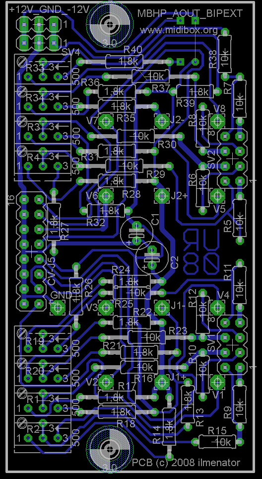
Some time ago before the summer I designed an extension board for the AOUT. It is untested, but it probably works. It carries the AOUT board as a backpack, hence the somewhat "difficult" layout. If you look closely, you will see that V1...V8, the +/-12V headers, the two dual row jumper headers, as well as the mounting holes share the same position on both boards. The two boards are connected using female headers on the AOUT_BIPEXT, whereas the male headers on the main MBHP_AOUT are soldered in facing down, that means the longer part of the header pin goes below the board. As I have some of the AOUT boards in a double sided version with solder pads on boths sides of the PCB, this will work nicely with my boards, it might be a bit more difficult with single-sided AOUTs. If you can find any bugs or have suggestions to improve the design, please modify and report back! Best regards, ilmenator MBHP_AOUT_BIPEXT_v02.zip
-
You could have added a tag!?
-
So, do you know how the checksums are computed? (Does Yamaha use checksums at all, btw? I remember that Roland has/had a pretty ugly checksum scheme in place... bah). I am not sure if I can be much of a help, having neither the DX nor the BCR. So this is going to be rather theoretical help, but I could try. Still, my advice would be to try it without investing in a BCR first. Use MIDI-OX to create some SysEx messages according to your implementation chart and see what happens. Also, I am quite irritated by the fact you want to use the BCR - aren't we a DIY community, after all? ;D A C language based MIDIbox would be the ideal thing. This way, you start small, try your code with only four or so pots / rotary encoders, and then when the basics are up and running you can extend. Best regards, ilmenator PS: You might want to look at the MIDIbox UC - unfortunately, the PC software has not progressed, so it is of limited functionality as of now. If you have some JAVA skills you might want to look at this, as it can do all that your box would need to do, and the same for all of your synths...