nILS
-
Posts
4,314 -
Joined
-
Last visited
-
Days Won
4
Content Type
Profiles
Forums
Blogs
Gallery
Everything posted by nILS
-
Before attempting to clone what Swindus' layout does I suggest you get familiar with the functions that are available to you :-) It is fairly easy to build a custom CS and just use whatever buttons you want. You don't have to stick to any of the given layouts. For instance you might use the built-in arpeggiator a lot - you might want a start/stop arpeggiator button. You might find yourself tweaking filter cut off and resonance a lot - you might want to dedicated encoders for that. As you see there's virtually a million possible different setups. One for each type of user. In a custom CS scenario, which only uses functions that are already available (in Step C for instance, that one has basically everything in it) all you would need to do is alter the matching setup_*.asm file by adding/removing a couple of lines that map your input devices (buttons/encoders) to the corresponding functions and assemble the new hex file (which is done by the assembler ;)).
-
There is absolutely no need for me to justify myself as your logic seems kinda blurred. "I can't find for whatever reason, so you have to prove to me it's there!". Sounds rather childish. You could just use that phrase in your initial posts from now on to point out how much research you've done prior to posting. Speaking of research - well, you obviously didn't look hard enough/at all. If you had you would have found what everybody else seems to have found and what was so nicely pointed out by Wilba already: "As the stock of these knobs have run out, Balthasar from ALBS told me he was thinking about manufacturing more. The minimum production is 5000 pieces, so he asked me what colour I preferred." Let's look at that statement for a second: Obviously, those knobs have run out. Balthasar from ALBS, who just so happens to be the owner of the company - which you obviously know, since you we're on the page - mentioned making those again. Way cool. But what's that? 5000 pieces. Looks like you'll have to buy quite a few. Of course this info might be completely old and wrong. Let's check their site to be sure - nope, they're still not listed. What to do now? How about sending this Balthasar guy an eMail? He should know, right? There's about 15 threads on this forum about those knobs. All of them saying "no, you cannot buy these, but hey there is/was/will be a bulk order". What more info do you need? If there's 15 threads saying you cannot buy those as an individual, there just might be a reason for that, don't you think? What ticked me off about your post wasn't necessarily the post itself but the fact that you start a thread for every tiny bit of info that you seem to need and are obviously not capable of or willing to find by yourself. Yes, there's a whole bunch of really helpful guys around here who are willing to help anyone with their DIY projects (DIY happens to stand for DO IT YOURSELF, note the yourself part) who gets stuck, but a lot of them (including me) don't feel like it's appropriate or worthwhile to invest a lot of time and energy into helping someone who is obviously not doing their part. Again: get over yourself. Start searching. If all fails, we're delighted to help you. Give us the feeling that you're too lazy to search and we'll "blast you" again.
-
Go for the optimized PSU since you have a C64 PSU. It is really not that hard. Some people do mess up the simplest things even if they are fully capable of building other far more complex things. Just take it slowly, read the manuals and documents available and you'll do just fine. You can't really judge how easy/hard something is by troubleshooting posts. Most people succeed in building it right away. You probably won't read a thread about that though ;-) edit: Beaten. Dammit. Nice to see that me and buhler agree though. See, we both say build the optimized PSU ;)
-
For some reason I assumed eagle wasn't gonna be on there. Silly me.
-
Yes, that's easy. No need to follow the really really hard tutorials on the net. I've put together a script that does all that for you. If you wanna test it, drop me a line and I'll link you. To install sdcc all you need to to is open a console and type "sudo apt-get install sdcc". For eagle, go to their site, download to Desktop, open console, go to desktop type "sudo sh downloadedeaglefilename" :D
-
For a bulk-orderable version I'd definitely go with more options for the footprints, ... For a DIY etch version I'd definitely go with bigger traces, bigger holes, bigger pads, ... If there's any interest I'd be happy to put together a layout for either option.
-
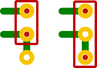
Exactly. If you look at the footprint you'll see it has 3 pins. Two of which are directly connected. So you can put different sized caps in there. Kinda like what you see in the attachment. I usually order from reichelt or conrad. Seeing that you are in the US this is not really gonna help you ;)
-
Get over yourself and stop yelling.
-
Ceramic caps in the nF range tend to get rather expensive. I'd go with polyester film caps like the WIMA MKS or the likes. Something like these:
-
I don't know how much the voltage drop differs on the different diodes, but I've used different ones in all osrt of layouts and never had any problems. Btw: "Building mbph Burner" - What's this "mbph" you are talking about? ;)
-
Correct. Guessing is not good enough ;-) Check the components that you want to use. Stick figure without arms... Yes, um, how about a link to a picture? I used special footprints that allow to use both 100mil and 200mil caps. Well, basically any trace should be as short as possible, but not any shorter. Parallel traces are bad as they introduce crosstalk, but don't hurt in a lot of cases. ...which is mapped to F6 on my eagle. Whoops :-) Almost. If you have mixed analog/digital circuits like the SID module you might want to separate the Ground planes or not have one in certain parts. Generally you do want one and you also want an isolation plane.
-
The middle pin is the wiper (s) is connected to the final (e) AND IC1:A AND R1. All of these 4 pins are on the same net and hence connected together. inital (a) goes to ground.
-
Pins 1 and 2 of the pot go to (IC1:A and R1), Pin 3 of the pot goes to ground.
-
Angel, wtf is wrong with your searching skills?! ::) Seriously now, this is getting way annoying. Read this ffs: http://www.midibox.org/forum/index.php/topic,11909.msg96836.html#msg96836 And use this ffs²: http://www.midibox.org/forum/index.php?action=search
-
I kind of interested in this, but I don't speak belorussian ;-) Are you guys trying to use relays for switching? If so, I just did in a project too, and it works like a charm. I found some really low current relays that only need about 5-7mA to switch @ 5V. If you're interested let me know and I'll throw some more info at you.
-
Sounds doable and is pretty much what's being planned to be done. This is totally the case. At the moment this can be done without much trouble simply by booting from the Ubuntu CD and running a simple script that I am working on, which "installs" ubuntu onto the stick in a pretty neat way - this way you get a persistent copy, whic saves and restores all your data *and* a fully functioning live stick, that'll run anywhere or could even be used to as an install CD ;D Which should be enough to setup up a USB stick. Even with the lousy that I am using atm, there's really not anything to be afraid of if you can imagine doing two simple things: * if you see a list of your drives you can identify your USB stick (for instance by size) * you can type two commands that kinda look like this "wget schickt.de/mbuntu/download/something" and "sudo sh something" Until there's a "real" distro, anyone willing to help with the testing, let me know, last time I check, it took me about 15 minutes to set the system up on a USB stick.
-
[solved] Encoder problem and other "scratch box" issues
nILS replied to Simson91's topic in Testing/Troubleshooting
stryd_one is partially correct. I used the mouse wheel in the first version and the voltags were in a 0.7...3.2V range. With the printed out wheel I get 0.7V and 4.2V so I guess that's not the problem. I'll try the new code and let you know what the results are! Thanks rasteri this thing is fun ;D -
A core + 2 SID board is already pretty advanced I would say. I have been working on mine for about 2 weeks until it kinda looked like it would work. That reminds me, I really need to get one made... ;)
-
Next time links us ;-) http://www.midibox.org/forum/index.php/topic,11707.0.html Correct. Correct as well. Yep, not having one/two/three banksticks is a major pain, as you can only have one patch at a time. But you apparently know that already. Correct. Well the bankstick "board" is so simple that there is not really a board. Some people have etched a bunch of them, but it's definitely easy enough to do on perfboard as there's not really any components needed except for the EEPROMs. If you mean a PCB for the optimized PSU, what I just said is valid as well. It's too simple, there's no ready-to-buy boards. Yes. There's a neat little "PIC ID" Calculator applet on Smash's site. All you need to do is set the deviceID to 0 for one and to 1 for the other - the rest will remain as is in most cases. No. Preprogrammed means it only has the bootloader and MIOS on it. You will need to connect the core(s) to a PC via MIDI cable and use the MIOS Studio Application that can be downloaded on ucapps.de to upload the Application. Programming - well um, not really. You do not have to actually code anything, depending on your CS you might have to edit some tables that have PIN numbers in them. That's really not a big deal though - there's even a nice little WIKI page about it ;-) You might want to post in his thread or write a PM to him about that ;-)
-
Pfft, you just don't know it cause you're never right! All the smart guys like TK, Wilba, bugfight, [add random names here] and me know it!
-
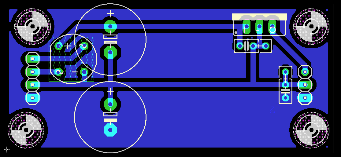
I don't quite see why you have all the text on both the tNames and 121_tsilk layers. Unless that's a batchpcb thing, it's not really a good idea ;-) The errors you get mean that there's something within the stop masked parts. That would be all the component outlines on tPlace. Hide the layer and run the DRC again, and you'll see. You've done some things in the layout that I cannot quite see a reason for, which isn't necessarily bad though ;) Footprints of 100nF/330nF caps tend to be 200mil - you might wanna check the parts you plan to use. I made some changes to the layout (the caps are supposed to be flat as in parallel to the PCB) kinda answering one your questions: Yes, you can route the signals like you asked. Why wouldn't you? As long as the parts are on the correct net you can basically wire them however you like (this is a half-truth. While theoretically you can, you wouldn't want to do it for various reasons. A bypass cap that is supposed to smooth things out for an IC don't help much on the other side of the board, HF traces (and all others really) should be as short as possible, well you get the idea). Before you start actually laying down traces, move the components around press F6 and see how the airwires change. That's another way of looking at the answer to your question ;D
-
Nah, the "I was right"-dance is one of the few dances that actually require standing up in the first place. I hate dancing.
-
that's even worse than, say, tattooing a Commodore logo on your arm ;D
-
stryd? Go to sleep. Right now. And don't you dare come back until you can think clearly again. There I was - absolutely convinced that in a MidiBox*cough* -excuse me - MidiBox-related environment it would be blatantly obvious that "mb" can only stand for one thing: my balls.
-
[me=nILS Podewski]does the "I was right"-dance[/me]