Wilba
-
Posts
3,310 -
Joined
-
Last visited
-
Days Won
2
Content Type
Profiles
Forums
Blogs
Gallery
Everything posted by Wilba
-
Interesting... After initializing the Ensemble, save it to E002 Reboot sammichSID. It should reload Ensemble E002 on startup. If the problem now has gone away, then it seems like it's just bad data in the Ensemble "Bankstick". You can perhaps try swapping bank 4 with bank 8, when you reboot it should reinitialize the Ensemble Bankstick (bank 8) and the 4th bank of patches (Bank C internally) and since you probably didn't fill up bank C yet, no difference to you, but possibly a freshly reformatted ensemble bank and no need to initialize every ensemble before use.
-
I have no idea what's wrong there... have you got the preset patches installed already? What happens if you init the Lead patch? Does pressing F1 button (Play note) trigger a Lead sound when it doesn't work via MIDI? did you solder R80? did you solder D3? check the joints on these first, and that there are no shorts with adjacent pads.
-
HOORAY! Don't worry about ugly. No one will see it, even if you do open up the case. :)
-
In my one I just roughly cut acrylic to the size of the LCD bezel and glued it to the back of the panel. It doesn't go in the panel cutout, just fills the gap between panel and LCD bezel and looks good enough. There's also a thread on the forum where Twin-x (and maybe Narwhal also?) are selling CNC cut acrylic windows for MB-6582.
-
M-Audio Delta 1010LT and MIDIbox wierdness
Wilba replied to Wilba's topic in Testing/Troubleshooting
Windows XP stopped booting, second time this happened this year, and I decided it was time to upgrade. It fixed some other problems I had - I bought a WD TV Live HD Media Player so I could play videos stored on PC, but it was dropping out every few minutes. It actually isn't bad, I haven't experienced any compatibility issues yet, everything just worked first time. -
My two cents... Cheap tactile switches with 0.25mm travel are good for control surfaces and crap for "instruments". If there was a good source of long travel switches that you can use for this kind of project, I would have found them already (or someone else found them). Either they don't exist in the "retail" market or they do exist and if you ever find them they'll cost US$5 or more each. The closest you'll get to cheap 4mm travel switches are Cherry MX switches. They come in flavours like linear and soft tactile. The contact point is at 2mm travel, NOT the full travel length. Maybe not ideal but you could reduce the travel to 2mm if you were creative. Caps are readily available but not in hex. It would be relatively easy to take an existing cap and chop off the actuator mount and glue/wedge into something else... or go to a place that makes custom caps. This idea is not new, and I'm doing a similar thing using Cherry MX switches, although I'm not wasting my time with hex caps. You should read through THIS ENTIRE BLOG before you start your project. http://musicscienceguy.vox.com/ You might decide to copy his prototype hex keys hacked into an existing keyboard's switch matrix, or just give up searching and buy the Axis. Like the others here, I don't want to discourage you, but building a variant keyboard is hard stuff, and expensive, if you want something that doesn't feel like a cheap toy.
-
I just noticed a very strange problem with my MIDIbox gear connected to my M-Audio Delta 1010LT. After upgrading to Windows 7, my MB-6582 refused to boot. The LCD would show black bars, there was no Bankstick tones. I opened MIOS Studio and restarted the MB-6582 and it was working fine. After some time (and PC reboots), the black bars came back. I started troubleshooting and discovered that with both MIDI In and MIDI Out cables connected to the M-Audio Delta 1010LT, it wouldn't boot. If only one cable was removed, or both, it would boot. So I finally realised that the problem was the 1010LT was in some kind of MIDI Thru mode, looping back MIDI In to MIDI Out, and the MIDIbox upload request was being looped back, keeping it in an infinite loop and never booting past the bootloader. Once the MIDI ports are opened, this MIDI Thru mode gets turned off, and it seems it stays off until a reset or sleep. I was happily running on Windows XP with 5.10.00.5057v3 drivers previously and it never went into MIDI Thru mode, I didn't even know it could do that, or why anyone would want it. During upgrading to Windows 7, I had to upgrade to 6.0.2 drivers since the old ones wouldn't install unless I used some compatibility mode trick so I thought upgrading was a better solution. There is probably a few MIDIbox users who have this card - 8x audio inputs/outputs plus MIDI makes it a powerful (and cheap) way to connect your MIDIbox synths :) Hope this helps someone else sort out their problems.
-
Raw SID sound through Sony MDR-7506 headphones makes my ears ring. :ike:
-
So does this mean the LEDs are working? There's a volume control for the entire SID, it's in the CFG menu. However, setting this lower actually increases the amount of digital noise on the SID. Don't ask me why. You probably shouldn't be plugging headphones into the audio socket, but if you want some way to adjust the volume, you can just attenuate it with some resistors or potentiometers, or get a volume control cable. http://www.amazon.com/Koss-155954-VC20-Volume-Control/dp/B00001P4XH
-
As the build guide suggests, switch to a Multi engine patch and play some notes, you should see LED bars showing as the engine cycles through each oscillator to play the notes. If you don't see LEDs showing, then something is wrong. It might be hardware related. Check you've soldered everything correctly on the control surface PCB. Did you perform voltage tests on the control surface PCB? If they all passed, you can try testing the LEDs... Take out the two 74HC595 Connect ground to one of pin 10-15 of IC3 Connect 5V to one of pin 10-16 of IC4 (connections can be done with a bit of thin wire like a cut resistor lead between pins of the IC socket) One LED should light. If it doesn't, the problem is in the soldering here, or the LEDs are backwards, or the resistors aren't soldered, etc. Try that first, if the LEDs are good then you can work towards the PIC looking for shorts/breaks.
-
No that's normal if there's no load... that's the input going into the 7809 voltage regulator. Once there's load, you'll see this drop to 11V.
-
LOL I forgot there were those panels made with silkscreening... ;)
-
Unfortunately it's not that easy. CS_MENU_L_ARP is an entry in the menu handler table, it's not a variable. If you're implementing what I suggested here: then you're calling a routine to toggle the "On" state of the arp on all the oscillators (i.e. setting 6 states on or off). So there isn't one state to use for the LED. Even if you wanted to cheat a bit and show only the "On" state for left SID's osc 1, then that state is one bit hiding somewhere in the patch variables, and to pull it out into a variable you can use in the DOUT table will take me more time than I have right now ;) But it's certainly possible. Asking for it is the first step, someone else might volunteer ;)
-
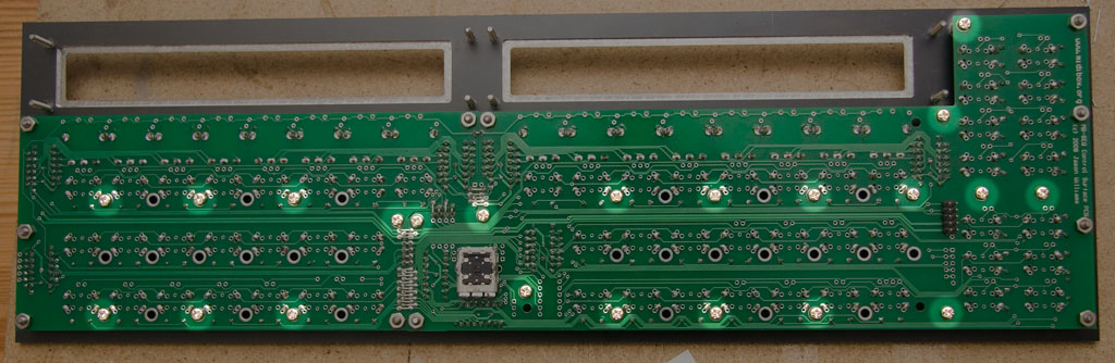
Yellowing is strange... not even my original prototype PCBs have that, and they're much older. The pads on the first run of PCBs might be a little tarnished (they aren't gold like the second run from SmashTV) but they should be OK. If you're concerned, use a bit of extra flux before soldering.
-
Looks great! Is there a reason you didn't add more spacers to support the PCB in the middle some more? My suggested locations were in the construction guide: http://www.midibox.org/dokuwiki/wilba_mb_seq_construction_guide
-
I can't logout of the wiki to test login! AFAIK it's the same username and password as the forum. Perhaps try resetting your forum password to something different. If the problem persists, send a PM to Twin-x ;)
-
Post a photo next to Machine Drum. This would be a good tease for the Elektron forum :P
-
Good to hear it is all working now! :)
-
Did you check the solder joints on header JMI?
-
Mine has 5V on pin 6 also. Is the shunt in JMI on the left?
-
Batch #2 was posted today. I have also updated the build guide.
-
m00dawg's sammichSID woes have been split into a new topic: http://midibox.org/forums/index.php?showtopic=13535
-
BTW if you refer to the Voltage Tests on the Base PCB section of the build guide, all the 5V and GND pads are highlighted. The short could be in the Banksticks sockets, lots of 5V/GND on adjacent pins.
-
Doesn't look too bad there... and no one will see it when it's finished anyway. Get the braid onto that mess on the ground plane. Finding shorts between 5V and GND is a pain. There are drastic measures for narrowing it down (like cutting 5V supply tracks to isolate which half of the track is shorting). However it is more likely to be around this big mess than anywhere else. The 7805 output and the 5V pin of the 100nF cap near it both look a bit messy, you should clean them up a bit and recheck. Just out of interest, is 5V or GND connected to the isolation plane? (the exposed plane under the heatsink) This is not connected to ground unless it conducts from the heatsinks (it doesn't matter if it does, but it might help isolate where the short is).
-
I don't get it either. Surely they could ask one of their bimbo groupies to build them a MIDIbox if they don't haz da skillz. :thumbsup: