seppoman
-
Posts
1,065 -
Joined
-
Last visited
Content Type
Profiles
Forums
Blogs
Gallery
Everything posted by seppoman
-
every MBSID "has the lead, bass and drum engines in it" because that's purely a software thing. I guess nobody ever spent $1500 on a MBSID (as long as it's not covered in massive gold). The mb6582 is already kind of the Mercedes version and Lucem just told you he's spent 400 euros on it. There's no such thing as "the average box" because any size or version is suitable for some uses or people. If you wanna have it cheap and quick, you can build only one core, one sid module, a small second hand LCD and a few knobs and buttons inside of an old wood box from your basement and it'll cost maybe 50 bucks and be capable of very nice sounds. Let's say the "average" price range is between 50 and 600 USD. You'll need to read a lot more on the forum/wiki/ucapps in order to find out what you really want and need. Before you know that, it doesn't make much sense to further speculate about an imaginary price of an undefined box. S
-
What was your problem with the original layout and what makes you think a different PCB version would increase the chance of getting a working MBFM in any way? S
-
Every switch has (at least) two pins. The "GND pin" is the one where you connect GND to. You can choose one of them freely ;)
-
Well "unreliable" is definitely the wrong word in that context (DW didn't collect money or promise a date before disappearing, right?). I don't know about Doug's medical or other conditions right now and am hoping he's well. Maybe/probably at times there are things in everyone's life that still are more important than Midiboxing. But I do think at least a little update on a time frame really wouldn't hurt. The original deal was that I would do the PCB order in August/September 08 and Wilba would take care of the ICs "soon". Handing over the bulk order for Americans to someone local in order to save on postage and distribute the efforts was a good plan, but if I was a participant myself, I guess I'd now wanna know about the future perspective myself, after looking at these beautiful and shiny PCBs for almost half a year ;) With these ICs also available from eBay (though somewhat more expensive), it would be cool if DW stated here whether he believes that he'll be able to handle that bulk order in the next 2-3 months, and if not, either let someone else take over the job or offer that people who're in a hurry and don't care too much about the price can cancel their orders and take care of their ICs themselves. Hope everything works out well both for DW and the chip order :) S
-
I said (or rather, confirmed) you have to use 4 AOUT_NGs on a mb-6582, that's a difference. So in case of a mb-6582, you've got 4 Core modules on one PCB and every one of them would be connected to a NG. MBSID can only control one NG per core, you can't chain them. The MBSID app is a good way of controlling filters because you get envelopes/LFOs that can be triggered by Midi events. As long as you're not using the complete regular sound engine for all filters and you want to save on Cores and NGs, you could also connect two of the ssm pcbs to one NG. That means you'd not use the regular Cutoff/Resonance controls of MBSID for the second pair of filters but access the CV channels via the AOUT menu and/or the modulation matrix. But regarding the original post: First, the SHX8 module is using chips that are obsolete, i.e. almost impossible to get. Then, do you want full Midi control over the filters or only a filter box with realtime control, i.e. only live knob tweaking (that's possible without even using Midibox stuff)? If Midi, would you need the additional ENV/LFO/MOD stuff that MBSID is capable of or is regular automation sufficient? In that case you could also think about building a little MB64 as just a Midi controller and two MBCVs that are receiving control data from either the mb64 or a computer/sequencer. Two because you could connect the two cutoffs and resonance inputs of the stereo filters together to just one pair of Cv outputs. Ok enough brainstorming for today ;) S
-
I guess that's a small documentation error and TK is talking about the SR chain pullups. These are R33-R36 in the DIN schematic (http://www.ucapps.de/mbhp/mbhp_dinx4.pdf). They make sure that the chain input of the last 165 chip (SER) isn't floating, i.e. doesn't detect random input events when no other 165 is feeding that input. If you put GND to that last SER input, it would make the box send note ons for the rest of the (nonexistant) chain, so it should read "It's only important that the last input shift register is terminated with a 10k pull up resistor to VCC on its SER input, so that the firmware doesn't recognize invalid values."
-
http://www.midibox.org/dokuwiki/doku.php?id=ssm2044_pcb_bulk_order We'll see :) S
-
Multi-Tap Transformers Versus Voltage Regulators?
seppoman replied to m00dawg's topic in Design Concepts
Another idea: maybe 6 or 6.3V is not enough to supply the 7805 under load condition? S -
Multi-Tap Transformers Versus Voltage Regulators?
seppoman replied to m00dawg's topic in Design Concepts
Hi, I don't have much time to answer right now, just one comment: "truncated AC" - you did notice that m00dawg has drawn the transformer input terminals in a way that doesn't make reading easier, i.e. the wire going to the 7805 input should be connected to the center tap? S edit: 808 posts, cool ;) -
Multi-Tap Transformers Versus Voltage Regulators?
seppoman replied to m00dawg's topic in Design Concepts
You have it all wrong :P No not really. I know this is quite a crazy concept and as I said, maybe it's better to use half wave rectification, and I didn't say I was sure it'd work under all conditions. But it's not that crazy after all: think about the way e.g. the Core module does its PSU section. GND reference from a rectifier is actually the norm for unipolar designs. From the theoretical point of view, it sure is rectified, because it's on the center tap and the rectifier on the outer taps makes sure that GND is always below and +12V is always above that point. yes, that's the point, as long as everything else is stable in respect to it. GND is only a question of the point of view. Think of the transformer plus rectifier as if it's a one-dimensional bird that is in flight and the position of its wings and body are voltages on this one axis. If you nail the bird's body to something fixed, like in a bipolar design, the wing's tips will move in positive and negative direction. But if you nail one wing's tip to something fixed and the bird still does the same movement, the body AND the other wing will move away from that point in the same direction. Strange picture, I know ;) So in that picture, it doesn't matter which point you define as GND, GND IS the reference so it can't have any AC in reference to itself. see above - in an ideal world, it is rectified. The only question that'd maybe spoil the concept is: Would unequal load distribution in conjunction with real world properties of the used parts (capacitance/inductance) lead to situations where this bird image doesn't fully apply? My suggestion is based on mere theory and is just an experiment of thought, not a recommendation based on real experiences. So if it turns out it doesn't work well in all cases, the other idea is to use half wave rectification, i.e. use only one diode on center and one outer tap and use the other outer tap as GND. S -
Core + LCD only Midibox LC as a display for Behringer BCF 2000
seppoman replied to alekzander's topic in MIDIbox HUIs
no. -
Multi-Tap Transformers Versus Voltage Regulators?
seppoman replied to m00dawg's topic in Design Concepts
oh not again please, I thought this thread was already beyond the point that this is NOT about a bipolar supply ;) so the center tap is definitely not to be connected to GND. This is about using a regular center tapped transformer, i.e. no extra 5v winding, to generate +9v and +5v. My suggestion on which this schematic is based is surely unconventional and there might be a reason I don't yet understand why this would only work well with balanced loads. If this is the case, changing to half wave rectification is probably a good idea (i.e. put only a single diode on each the center and + output, continue to use the "-" output as GND and go on from there). S -
no not yet. A few days ago in another thread, I promised (again) to publish it in the next few weeks :)
-
how did you test that? If the caps were desoldered for the test - no idea. if you're measuring continuity on them while they're still on the PCB that means you've got a short between 5V and GND. S
-
oh yes it does need some improvement ;) your construction would need a 200mV battery and still wouldn't output a bipolar voltage. But a battery is the wrong solution anyway. I said "the input of the 2044", not "the input of the module". That's a difference! In conjunction with an AOUT_NG with bipolar mode, that module input gets (expects) around -5V..+5V. You could try using two 3.something k resistors and a 2.7k Pot inbetween to build a voltage divider between the +-12V rails that outputs around +-5V. But I'm not quite sure if the frequency range would be as expected. Even if it works, using a stereo pot would be a good idea. The clean solution would be to add an opamp cirquit to transform the input to a V/oct one. I promised a long time ago that I would publish a schematic for that... If you can wait for some more weeks, it's definitely on my agenda. If you're in a hurry: http://www.analog-synth.de/synths/mod2/ssmlowpass/ssm2044.pdf You can see the standard implementation on the right side of the schematic on page 3. That way you get trimpots to adjust range and offset. If you build that cirquit for both SSMs, you can safely use a single pot connected to GND and 12V to control both at the same time and match the response of both filters perfectly. S
-
Core + LCD only Midibox LC as a display for Behringer BCF 2000
seppoman replied to alekzander's topic in MIDIbox HUIs
but you'll want the BCF to receive the data, too, so it needs to be duplicated somewhere. the MBLC Midi out isn't suitable for chaining these boxes and shouldn't be connected to anything. You won't necessarily need an extra thru box, an LTC module providing a Midi thru port is sufficient. S -
cool audio, a source for new analog BBD delay chips :)
seppoman replied to Artesia's topic in Parts Archive
That's really a strange company. I wonder if they really "developed" and are manufacturing that stuff they're offering or if it's only about relabeling the ICs. on the SSM2164's datasheet they didn't even try to make it look like the app notes are not copied from AD's datasheet ;) BTW, wrong forum section ;) S -
Core + LCD only Midibox LC as a display for Behringer BCF 2000
seppoman replied to alekzander's topic in MIDIbox HUIs
that's kind of what I meant. just use a "Midi splitter" (I think these are called a Thru box) to send the PC's Midi out to both the BCF and the MBLC and Midi In of the PC just connected to the BCF. That way it's even irrelevant if the MBLC sends stuff or "leaves the data untouched", the PC won't notice. yes that's right, the Mackie/LC is just a dumb remote, as soon as it's online it will display anything (and nothing more) that the PC sends. S -
MBSID V2 (8xSID+8xMoog): The Rutger Edition
seppoman replied to rutgerv's topic in MIDIbox of the Week
-
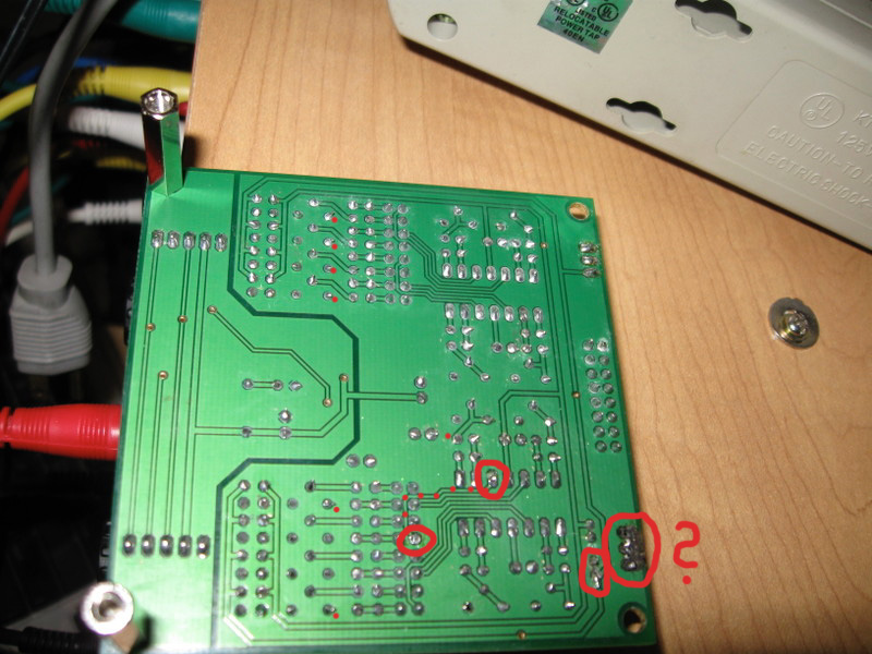
What I meant to say was: the "gnd pour" on the bottom side, analog section (right hand on your pics), shouldn't have connection to ANYTHING, i.e. including GND, it's just there for a little shielding but has no function. But if you damaged the solder mask laquer and made connection to it on more than one occasion, it could be responsible for a short, too. Anyway, maybe try to resolder a few things and carefully inspect the whole area around the jumpers and IC3 under a good light and maybe a magnifying glass. Keep trying to solve that problem with removed jumper and IC3. If you can't find anything, you could try removing the IC socket or the jumper headers, although desoldering on double sided PCBs is never easy and your J3 doesn't exactly make you look like an expert in that field ;). A way to check at least one place from above without risking to damage the PCB is to remove only the black plastic from the jumper headers. Normally you can move that plastic if you're patient and maybe heat up the pins a little. S
-
Core + LCD only Midibox LC as a display for Behringer BCF 2000
seppoman replied to alekzander's topic in MIDIbox HUIs
The host would still be the PC. I guess the BCF just ignores the LCD commands as it doesn't have LCDs. I've read through the LC/Mackie protocol specs a few years ago and if I remember correctly, there's no way the host could ask if a LCD is present (wouldn't make much sense because the "official" units all that their LCDs). So I would try to use some Midi splitter to duplicate the Midi out coming from the PC and feed that into a MBLC that has only LCDs connected (no Midi out either). This would probably work fine. S -
yes and while these sockets are really nice, I didn't find any Midi version of them. If they exist, they'll surely cost 3-5 Euros each. Together with the GM5x5x5 module and a case that's 70-100 Euros alone, you'll end up with a unit that is more expensive than a used or even new 8x8 Midi interface by e.g. MOTU/MAudio/whoever. DIY is nice but I don't see a point in spending more money for a Midi interface than for a commerical unit that even has more ports. S
-
Good morning m00dawg ;) http://www.ucapps.de/mbhp_core_stm32.html There's also a lot of stuff already done for Seq V4 on STM32, bootloader, MIOS32 etc, so I guess you're a bit late for suggesting other controllers :) S
-
Well if you want to use that chip, of course you'll need that module. But the GM5 does have some advantages (better Midi driver under Windows, no need to upload any firmware to the chip, possibility of adding up to 5 ins and outs...). Don't know when the next bulk order will happen, but the GM5 chip is only 5 Euros and the rest of the cirquit isn't more expensive than the USB module either, so if you're not in a hurry and are not absolutely set on using the AN2131SC, if I was you I would choose the GM5 way. S
-
did you also measure with the jumper completely removed (not only turned sideways)? With Jumper and IC3 completely removed, the marked trace should not be connected to anything. which place of bottom gnd pour did you measure against? the gnd pour on the analog side (right) is normally not even connected to anything, so the problem can only be on the bottom side if more than one solder joint makes connection to it. Make sure that none of the solder joints touch it (normally that's no problem but maybe you've damaged the laquer somewhere). Especially resolder both joints on that marked trace. A problem on that trace occurring on the top side isn't very likely, the tin normally doesn't go through the holes in large amounts. J3 also looks dangerous. I can't really see what's happening there due to image resolution, but try to remove all solder on top and bottom side, looks a bit like you have some interconnection there. S