Sasha
-
Posts
1,944 -
Joined
-
Last visited
-
Days Won
3
Content Type
Profiles
Forums
Blogs
Gallery
Everything posted by Sasha
-
I have experienced flickering LEDs in past with other project and it didn`t stop when I add terminators at the end of the chain. A friend of mine had similar problems too, so I get DIN DOUT registers can be problematic sometimes and especially if they are not routed properly.
-
Sure, 1.27 is not hard to solder, but still it would make it undesirable to people with less soldering experience. Another reason is doing all the work again. It took me a lot of energy and time until I was completely satisfied. 14 register ICs are too much if it can be done with only 4 or 6.
-
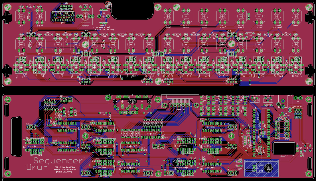
Well, you can help if you know how to configure MB808 firmware to work with BLM, it will free a lot of room on PCB, so I can make new layout and route SC/RC lines properly. I was checking the code of SID, and SEQ app. but to me it looks they are configured completely differently and I cant figure out those virtual registers. On SEQ virtual registers are counted from 17 to 24, but where in the matrix should be connected button 17? I didn`t find any schematic with labels where is physically each virtual register located on the matrix net. In the MBSID, register configuration is done with "16+" which is even more confusing to me if I try to compare it with MBSEQ. Only thing understand from the code is how to enable firmware to use it BLM, but not how to use it. Maybe I`m bit rusted from the years of inactivity or maybe it is just too complicate for non-programmer like myself to figure it out. Look at the attached picture of my PCB design showing SC line highlighted. This is not how register ICs should be routed. SC/RC lines should go from first SR to last one, and separate for DIN and DOUT, but I find out too late about it.

-
Just to let you know I trashed my PCB design. :( When I finished everything and just before I sent files for PCB prototyping, i read the thread about possible problems if SC/RC lines are mixed between DIN and DOUT registers, which is exactly the case with my design. Maybe there will be no problem as all the register ICs are pretty close to each other, but I can afford only one prototype set. The PCB is pretty dense so there is no way I could re-route the lines properly. If somebody is willing to help me with matrix I could make new design, but there is no way I route again PCB from scratch with all 14 registers. Sorry guys.
-
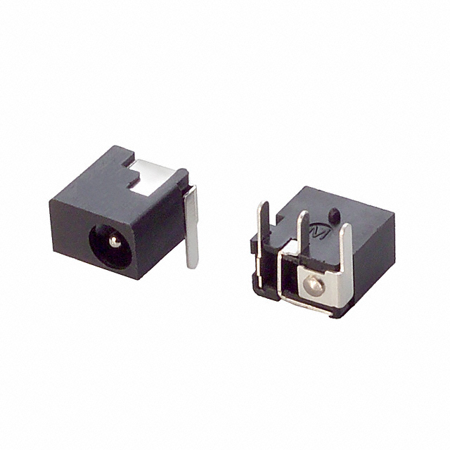
I`ve found a low profile barrel switch. It is 5.5mm high Datasheet: http://products.cui.com/GetSpecForDigiKey.aspx?MFGNum=PJ-014D

-
Thanks mate. That is great. I really like that switch. One part sourcing problem is solved. Do you have some extra x0xb0x/MBseq style buttons left? :P :D Hmmm, i totally forgot about those. Thought MIDI sockets and 2200uF capacitor are only thing to worry about. And, I thought this is final revision... I didn`t see all the kaffeSEQ details, but I really like how it is done. Great work Nils! Sure, we are all here to steal each other knowledge and experiences. ;) My initial idea was to use metal epoxy to glue 5mm female metal spacer to the long vertical spacer that holds 2 PCBs, but I think this is better solution. Meanwhile, I changed this idea, again... Even I really like laser cutting sometimes it is needed to employ other machines or even hands in the worst case. So, instead of using vertical acrylic plates and glued nuts, it is really better to use 3mm aluminum plate and make an M4 thread in it, even I need to make a thread by hand.
-
Even there will be just 3 locking peaces visible on front and back panels, and if you are perfectionist, like me, you can hide it by gluing the pieces and repainting it. Here is how it looks at my Clockbox example. As I really like the design of Clockbox, I`ll be doing it again with case for Drum Sequencer. All crews visible from the top will cover 1.6mm laser cut/engraved Rowmark sheet with just 4 screws visible in the corners. Same as I did here...
-
Well, long time has passed since that, we`ll see. I would probably need some help regarding organizing batch of buttons and caps from Digikey or Mouser.
-
As some of you know from the past, it is mission impossible to organize PCB batch from Serbia on my own because of the very strict customs rules, but PCBs and laser cut/engraved acrylic case will bee very probably offered trough local company that will act as a payment/shipping gateway. I`ll have more info about it once I finish prototype. Well, as I will be making panel for my 9090, I can probably help you get custom 9090 panel that feature this sequencer and 9090 pots. Here is my old design, but as it will be no batch for that, you can make any customization that you like. ;) You asked about PCB dimensions before you edited the post? They are 325x89mm
-
Well, I was forced to find some different solution without changing dimensions. I`m glad it makes sense. :) That`s cool. I just added those resistors. Sure! I did that too. Thanks for the tips! ;)
-
I thought I finished PCB designing than, after talking to Wilba, I decided to make some more changes. He suggested to use 10mm spacers as he did on his Kaffe sequender, instead of 20mm, so I did it. Early in this thread I was thinking to use mini DINs, but as it is not used on any gear I quit the idea. In order to use standard DINs, I needed to make some compromises. I left out one encoder to make room for sockets, so now there are 2 knobs instead of previous 3 - tempo and swing. Instrument knob isn`t really necessary. I thought it would be cool to use it to send master volume CC. There is a cutout in the CS panel (as on on Kaffe), so DIN sockets are sticking trough it. Main board PCB also has cutout for 2200uF capacitor, in order to fit in sandwitch. Another change is Sync24 out. I really didn`t wanted to left it out so I`ve decided to use MIDI in socket as a Sync24 out. MIDI uses 3 middle pins, and Sync24 out`s "run" and "clock" signals uses 2 outer pins (1 and 3). Only "continue" signal uses pin 5 used also by MIDI, but "continue" signal isnt used in the drum sequencer so I guess it shouldn`t be a problem. What do you think of it? Are there any reasons not to use one DIN socket for both? I really could`t make more space without altering PCB dimensions. Here is how the PCBs looks right now.
-
Hello everyone! I was out of the community for quite some time, and feel little bit rusty. :)Anyway, I`m ready to get back on track, and I`m glad to confirm I`m continuing with this project. ;) Soon I`ll make prototype PCBs and let you know the details.
-
Optrex makes very nice 20x4 negative white/black displays.
-
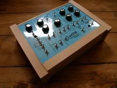 Looking good. I love that fat wood!
 -
Edges can be fine sanded and they will look almost the same as sides! ;) this is made the same way... you can`t even see the joints.
-
That is Re`an too, model P670. You can find it everywhere, ebay, mouser, rs...
-
Re`an P401 http://www.midibox.org/forum/index.php/topic,11050.0.html
-
http://lividshop.com/hardware/rubber-key-pads.html Product Description Our translucent white silicon rubber keypads have 64 buttons plus 2 function buttons on the bottom. Each button has a hole on the bottom to allow for LED illumination. The buttons have a conductive backing for creating a contact to a circuit board. The button pad can be easily separated with a razor blade (at your own risk of course) to create a different layout. These are the same buttons we use on our Ohm64 and block controllers and do not have any printing on them Pad size 6.625†- width 7.5†- length .75†- height Button Size 0.5†- length 0.5†- width .625†- high 4x1 version http://lividshop.com/hardware/4x1rubber-key-pads.html Our 4x1 translucent white silicon rubber keypads have 4 buttons . Each button has a hole on the bottom to allow for LED illumination. The buttons have a conductive backing for creating a contact to a circuit board. The button pad can be easily separated with a razor blade (at your own risk of course) to create a different layout. These are the same buttons we use on our Ohm64 and block controllers and do not have any printing on them Pad size 1†- width 4†- length .75†- height Button Size .625†square
-
Thank you very much Wilba.
-
Well, because of the US$200-US$250. Don`t get me wrong. I don`t think it is expensive, but I already have all the parts to build it and laser cutter at hand for making custom case at low price. I could make it pretty cheap if I can buy just PCBs. If you sell it just as a kit, I understand. No problem.
-
That is very cool compact design Wilba/Nils. I`m not sure I get you right... will it be sold only as a kit with/without SID, or you will sell just PCBs too?
-
Very nice work! ;)
-
Very nice demo, Thorsten! ;)
-
Glad so hear it works good! :) I have no idea how to test it more intensively.
-
PCB have footprint for pot and pin connector, you can use it for whatever you want. In my case it will be for master level.