-
Posts
281 -
Joined
-
Last visited
Content Type
Profiles
Forums
Blogs
Gallery
Everything posted by xarolium
-

USB host doesn't work but i follow the TK topic
xarolium replied to xarolium's topic in Testing/Troubleshooting
Thank you for your reply. I will try a other cable and let you know -

USB host doesn't work but i follow the TK topic
xarolium replied to xarolium's topic in Testing/Troubleshooting
Thank you for your reply, PA9 is the VBUS_FS line on the discovery board. As i power my Keyboard with a external power it does not change anything. I tried to connect PA9 to +5V but still no midi message from my Oxygen49 Any other advice ? -
Hi there,"USB MIDI 2x2 i 'm trying to build a very simple USB host to Midi converter with the USB_Midi_2x2 app. I have a Discover board MB997D, i uploaded the bootloader and the board respond correctly in MIOS studio, then i uploaded the USB_MIDI_2x2 hex file and the Discovery board is well recognize as "USB MIDI 2x2" in MIOS studio. Then i disconnect the micro usb cable and connect my keyboard (a Oxygen 49), i reset the Discovery board, then i tried top play some note on the keyboard but nothing happens, no data in MIDI OUT1 and the green led DOES NOT blink on the Discovery board. The oxygen 49 is powered by a external PSU. I made a custom USB cable that allows me to connect the +5V rail to a external PSU. Any idea what i'm doing wrong ? Do i have to compile the app with #undef MIOS32_DONT_USE_USB_HOST ? Any help will be much appreciated
-
Hello everybody, like marcos asked two years ago, i also want to add MIOS32 to STM32IDE. I follow the steps on th great tutorial made by BEBDigitalAudio but when i tried to compile a apps i got the following error. I also think i didn't understand how to access to file with Tortoise SVN. Can somebody help me please. make all Makefile:73: c:\mios32\trunk/programming_models/traditional/programming_model.mk: No such file or directory Makefile:76: c:\mios32\trunk/modules/app_lcd/Universal/app_lcd.mk: No such file or directory Makefile:79: c:\mios32\trunk/modules/midi_router/midi_router.mk: No such file or directory Makefile:82: c:\mios32\trunk/modules/midimon/midimon.mk: No such file or directory Makefile:85: c:\mios32\trunk/modules/uip/uip.mk: No such file or directory Makefile:88: c:\mios32\trunk/modules/uip_task_standard/uip_task_standard.mk: No such file or directory Makefile:91: c:\mios32\trunk/modules/freertos_utils/freertos_utils.mk: No such file or directory Makefile:94: c:\mios32\trunk/modules/keyboard/keyboard.mk: No such file or directory Makefile:97: c:\mios32\trunk/modules/ainser/ainser.mk: No such file or directory Makefile:100: c:\mios32\trunk/modules/aout/aout.mk: No such file or directory Makefile:103: c:\mios32\trunk/modules/max72xx/max72xx.mk: No such file or directory Makefile:106: c:\mios32\trunk/modules/ws2812/ws2812.mk: No such file or directory Makefile:109: c:\mios32\trunk/modules/notestack/notestack.mk: No such file or directory Makefile:112: c:\mios32\trunk/modules/fatfs/fatfs.mk: No such file or directory Makefile:115: c:\mios32\trunk/modules/file/file.mk: No such file or directory Makefile:118: c:\mios32\trunk/modules/md5/md5.mk: No such file or directory Makefile:121: c:\mios32\trunk/modules/sequencer/sequencer.mk: No such file or directory Makefile:124: c:\mios32\trunk/modules/msd/msd.mk: No such file or directory Makefile:127: c:\mios32\trunk/modules/scs/scs.mk: No such file or directory Makefile:131: c:\mios32\trunk/include/makefile/common.mk: No such file or directory make: *** No rule to make target `c:\mios32\trunk/include/makefile/common.mk'. Stop. "make all" terminated with exit code 2. Build might be incomplete.
-
Yes it is a Wilba based design but with my own button (cherry and standard illuminated 6mm squared button)
-
Zam, Thank you for your reply The P&G motor is a Escap 22S28 210E and seems to work with 12V and draw 0.3A I'm thinking of using Analog signal to driver motors instead of PWM. I 'm inspired by the SSL Ultimation schematic 82E353 to design my own PCBs. SSL use opto isolator to isolate power Motor and DC control/audio. I also looked at PID control like this one Now i still have to prototype and make some test. Maybe you can share your experience with your 89Motion project ? What do you advice to get the best result (less noisy fader and smooth movment) ?
-
Any help here !
-
Hi Diyers, Since @Zam built his wonderful moving fader console i 'm thinking of doing same thing on my Amek Galileo, the problem was to get the right fader to work with GAL10 channel. I finally get some of Penny and Gile PGFM3220/D fader to start this project. I tried to control the PGFM3220 with the MF_NG module but it was impossible to get the fader moving smooth and the motor is huge noisy by setting MIOS Calibration App. So i'm considering using a other driver like the ST L6201. Do you think it will solve the smooth movement and noise issue ? Your help is pretty much appreciate to put me on the right way to get it working Thank you
-
Hi There, I'm cleaning my workshop and i found lot of oldies i don't want, so maybe you will be happy to get it Here is the list: -Dual SSM2044 VCF PCBS x5pcs 5€/pcs -IIC Midi Module populate 10€ both -Midibox SEQ V4 custom PCB x 4pcs 25€/pcs -Midibox CV all in one PCB Pcb 10€ -Midibox Ultracore 10€ -Digisound 80-2 VCO x3pcs 10€/pcs -Thomas Henry VCO 555 10€ -Lot of Roland system 700 PCBs replica 8x PCBs (3x VCA Model 704, 1x S/H Model 709, 1x Noise/ring Model 708, 1x Dual ADSR Model 705, 1x VCF 703E, 1x VCF 703B) 95€ all -Ryk Sequencer Kit V2.3 polpulate with switches (cf picture) 50€ -X0xb0x Main PCB + case 70€ Paypal prefered, price ex shipping (worldwide) Thank you ;)
-
Any news ?
-
By the way do you need help to design a new pcb, I m prototype designer and can provide some service to help day community ;)
-
Is it true ? can't wait
-
Hi there, i would be very happy to buy a pcb for this project,any left? And what about the case? thank you
-
Zam, Thank you for your answer The problem is not how to interface the console with the DAW cause it already works pretty well. The issue is that actually protools allow me to set only four HUI interface so it's 32 channels and i would like to control 48 channels. My question is how to modify this 8 channels per HUI limit or is there an other protocol that allow me to control 48 channels.
-
Yes but it allow me to control only 32 channels (4 x 8 channels) and i need 48 How can i do it ?
-
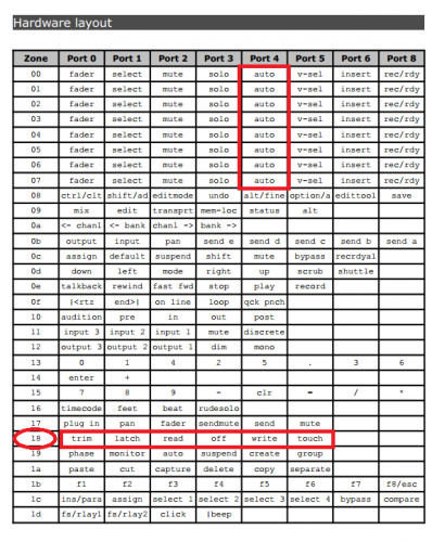
Ok after i wrote the first topic i found how to control Trim, Read, latch, Auto functions of the channel. I simply was trying to use the wrong zone. As describe on this table, Port18 is used to control those parameters and i did it with success ;) The only thing i still have to found is how to control more than 8 faders at the same time Thank you for your help
-
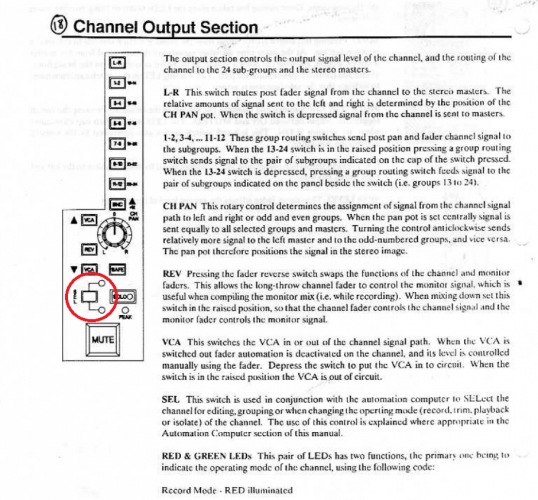
Hello every Midi Diyer, Some time ago i bought a Soundtracs Jade console 48 channels. What a wonderful no so expensive console it is ! The first version of the Jade console came with a "TrackMix2" old computer that allow users to automate the VCAs of each channels, but this system is completely obsolete and nobody know how to upgrade it (i contacted Tim from www.studiosystems.co.uk but he doesn't know anything about it, no schematic of service manual...) So i decided to recreate those but with more fun function like controlling protools parameters. I use the HUI protocol to control faders and mute but i only can control 8 faders at a time as i have 48 of them on the console. So HUI protocol is very limited. Then i would like to control the "Read", "Touch", "Latch" ... functions with the SEL (Cf picture) button on the channel. Originally this button was used to control the old computer. The thing is that HUI protocol do not allow me to control this parameters. I tried to sniff protools midi out when changing this parameter and it return : B0 0C 0x, B0 2C 4x (where x is one of the eight zones). So i send this data from my µC: B0 0F 0x, B0 2F 4x (like describe on the HUI protocol) and protools return to the µC two sysex array : F0 00 00 66 05 00 10 00 52 65 61 64 F7 F0 00 00 66 05 00 10 00 41 75 64 31 F7 As i know "F0 00 00 66 05 00" is the Header, 10 00 describe a Text message and the letter "Read". then "Aud1" the channel name So it's not what i expected. Do you have some information about how to control "Read", "Touch", "Latch" parameters in protools ? Is it a protocol that allow me to control more than 8 channels at the time ? I saw the is interface for SSL4000: Tangerine for SSL and on the demo the guy control those parameters with the SSL with HUI protocol. But HOW ? i asked him but no respons Thank you for your help
-
Great ;) I would be happy if you share your Eagle files than i would make my own PCBs too and share the extra with the Midibox community ;)
-
Thank you for your answer. I have an other question about dual colours leds. Green leds on GP leds are only use to display current playing step, isn't it ? so why not simply be the red leds state inverted during half lenght between two steps. I explain myself: if they are 24 clock ticks between each steps the current step led will be inverted only 12 ticks that will make the visual step clearer especially if all 16 steps are On without the need of the second leds. Does it make sense ? Where, in the code, can i modify this thing ? I try to find a solution to not use this second green leds because cherry switch led location do not match with 3 pin dual color led. Can i still use Wilba 8x8 matrix if i do not use dual colour leds? Best regards, Xarolium
-
Dear diyer, I want to design my own SEQ V4 PCB with Key switches (Same used on Circlon sequencer) and illuminated encoders. The Encoder leds will display the current active step and i want to get 16x4 button/leds matrix. My question is, can i used the first row of the 16x4 button/led matrix as GP button ? Thank you for your help Xaro
-

How to scan 16 encoders using shiftregister ?
xarolium replied to xarolium's topic in MIOS programming (C)
Dear TK, Thank you for the link, I spent lot of time to find this without success, i should be blind :pinch: Best regards, Xarolium -
Dear TK, I 'm building a midi interface based on Teensy3.1 (i know it will be simple to use Core32 module instead but don't have one yet) and i add 16 rotary encoders to my project connected as describe in the DIN module page. The problem is that i try to code to interface with the encoder but result is not very accurate. Could you share your piece of code you use to scan the encoder or put me on the way to get good result ? Best regards, Xarolium
-

Midibox CV 1.3. Start/ Stop and CLK doesn't work
xarolium replied to xarolium's topic in Testing/Troubleshooting
What shame, I did not select the right pin in the program. everything is back in order. Sorry to have called into question the code. Thank you for your work ! Best regards, Xarolium -
Dear Midiboxer, I updated my Midibox CV1 to the 1.3 version and no more CLK and Start/stop pin stay at 5v I came back to the 1.2c version thne everything working fine. I think there is a bug in this version Best regards, Xarolium
-
you can find similar board here http://www.e-licktronic.com/en/produits-arduino-midi-controller-diy/24-lcd-adapter.html


