

Digineural
-
Posts
109 -
Joined
-
Last visited
-
Days Won
1
Content Type
Profiles
Forums
Blogs
Gallery
Everything posted by Digineural
-
I'm building a MB64e based dedicated controller for another synth. The controller will just send CC events to the synth for parameter changes but I still want the synth to get all the MIDI messages coming into the controller from a sequencer. Does MB64e natively support forwarding or do I have to implement it in void MPROC_NotifyReceivedEvnt( unsigned char evnt0, unsigned char evnt1, unsigned char evnt2) __wparam { ... } such as found in the tutorials? Best regards, Dan
-
I've completed a design like that which worked fine so far. If its critical though, I would get a second opinion. But I think you're ok. If I'm reading the datasheet right though, UGND (pin 28 next to D+) should still be connected to the USB ground (Per page 96).
-
Depends, if the LC boards and the GM5 are sharing the same ground and +5, (i.e. not from the PC) then it should be ok for a direct connection. If you're using the prefabbed boards from Tim or Mike, then you're best using the optocouplers to isolate the rails since its likely that you're not going to power the whole system over USB. Without it, you could do some amazing damage to both the LCs and your PC
-
I sent you a PM
-
Forget it, just RTFM. Interrupts are a complicated beast on the STM32 will likely require some work in FreeRTOS that is beyond the scope of doing something easily. I'll just scan the matrix
-
I'm using the STM32 version of the Core32 and I'm getting stuck on implementing the general I/O expander MCP23S17. My goal is to use this over SPI on J19 to monitor inputs on an 8x8 switch matrix. One of the cool features of the MCP23S17, is that it has interrupts on either the row or column side (PORT A or PORT B). I'd like to be able to only cycle through the matrix only when the interrupt flag has been raised to help with performance. I know I can always use the tried and true method of a DIO_MATRIX module, but I'm trying to reduce the component count and make a board that is single side friendly. Any thoughts on free pins that can be used as an interrupt? I'll be using J8/J9 for a few DIN and DOUTs and J15 for LCD.
-
I got a few spare GM5 ICs (straight from ploytec) that I'm willing trade for a GM5x5 PCB. Let me know if you're interested.
-
Good to see another meeblip.<img class="bbc_emoticon" alt=":thumbsup:" src="http://midibox.org/forums/public/style_emoticons/default/thumbsup.png"> <br><br>I got a micro, which is a ton of fun to use with FLStudio, but I'm less than impressed with the lack of storage and using potentiometers so I'm boxing mine with a MB64e (or maybe something more dedicated) so that I can do patch saving and recalls. Just finished the 2u panel layout last night. Its nice to see them with a custom enclosure.<br>
-
 I see you've got solid wire, leads and verowire connections. Did you start off using leads and resign to vero?<br><br>I'm wrapping up my SEQV4 on perfboard and I'm envious of people who use a veropen. Its elegant compared to my crude wire leads and solder-blobs.<br><br>Either way, your minimal sammich-swin is looking good!<br>
 -
You'll program the firmware for the right project. The firmware sits on top of the bootloader and MIOS. You wont need a burner to program the firmware. The bootloader knows what app its running because its the only app programmed. Lets say you get a pre-programmed IC with the bootloader, or you program the bootloader on a raw IC, you still need the application. Lucky for us the application can be loaded over MIDI for the Core8 and USB for the Core32. You can upload the application using MIOS Studio in both instances. The Wiki is another good place to get more information.
-
Head over to uCApps. On the left there is a menu. You'll find the MB64 project under "MBHP Projects". Read all those pages to get a high level understanding of the MB64. As far as the hardware goes, you have a few options. The old MB64 project uses: A PIC based core and a PIC18452, I think you can get away with a PIC18F4520 and the low power variants just fine. A DIN module for each 8 buttons or 4 encoders. A DOUT module for every 8 leds An AIN module for each pot/slider To be honest. This was my first MB project I completed almost 10 years ago. Start small and add modules as you go. You can also just start with a standard control surface setup and go with the Core8 or Core32 following the Programmer Tutorials. The Core32 is nicer to work with and instead of the AIN module you'll use the AINSER64 module. Best Regards
-
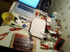 I would say that's a pretty common setup in the DIY world. I built my MB6582 at my table while my wife read a novel out loud next to me. One of the most rewarding weeks of that summer.
 -
I've been thinking about this for the last 2 days and was considering placing 2 medium sized duo color 8x8 led matrix side by side for a 8x16 matrix. Then placing a PSP touch screen on top and mapping the coordinates over the leds. Someone did the same thing about a year ago and it was a pretty cool project. I suspect that given the small form factor of the led matrix that it will be prone to fat-finger errors but it might be fun to try it out. I think the parts can all be sourced from Sparkfun and the like. In case anyone was wondering, the medium sized matrix at Sparkfun is just under half the width of the PSP Touch Screen making 2 led matrix optimal.
-
I want to learn programming. Where do I start?
Digineural replied to JRock's topic in MIOS programming (C)
Arduino is a good start for getting used to C coding structure, data types, registers and hardware programming. Its also helps deal with the concept of code abstraction layers. MIOS8 and MIOS32 are both abstraction layers that handle common routines on top of the specific platform architecture. Since TK does a pretty amazing job at abstracting routines in the MIOS, most of your custom programming with be with MIOS routines. So it's pretty safe to go that far without having to dive to deep into the platform specific architecture. Then again, you can always go deeper. :whistle: If you're planning on doing MIOS8 programming though, you might have to get into some ASM, whereas the MIOS32 is all C++. C/C++ also transposes well into Java and C# if your going to extend your knowledge, as they are similar coding styles. Albeit targeted to different platforms. Good luck! :thumbsup: -
I'm looking to map UI input buttons to an input matrix that is managed by an IC over IIC. I think I'm having a little trouble modifying the SEQ to manage this process. Here is a rundown of what I was looking to do with the least evasive code changes possible. I'm merely asking if I'm moving down the right path or if there is a better way. I can only have up to 12 switches per IC and only 4 addresses on the IIC bus so that still leaves all the encoders and a few switches to still go through APP_DIN_NotifyToggle 1. I want to create a mapping table that defines a IIC mapping to SRIO mapping using the following layout: IIC ADDR, IIC PIN, SR, SR PIN 2. I thought if I create a new TASK, that I can copy APP_DIN_NotifyToggle and modify it to look sort of like the following but the key is passing everything to the existing button handler typedef{ u32 pin; u32 pin_value; }tIIC_Input_Mapping; void TASK_IIC_DIN_Handler() { // Convert the IIC input to a DIN mapping tIIC_Input_Mapping IIC_Input_Mapping = IIC_TO_DIN_MAPPING( /*IIC Input logic here */ ); // forward to UI button handler SEQ_UI_Button_Handler(IIC_Input_Mapping.pin, IIC_Input_Mapping.pin_value); } Thoughts? Am I moving down the right path?
-
Sick! I love the rotate feature. I hear you on the ALBS waldorf knobs. I recently switched to smaller soft touch RE'AN knobs on the smaller projects
-
Nice! I need to stop working in my CNC and get back to this project. :smile:
-
recommend a sw sequencer to control HW synths??
Digineural replied to Nestle's topic in Songs & Sounds
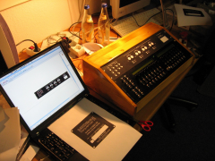
I've been a fan of FLStudio myself. I don't use the standard sequencer, its sort of old school. Instead I use a MIDI out channel and leverage the piano roll feature. From there I layout song sections in the song pattern editor. It has a lot more options and works quite well with my MB6582. Pretty much all my projects start in FLStudio then branch out into other tools as I need them. -
wow, I'm not even up to that just yet. Still working through my 4th revision of the base PCB. I'll share it once I get everything tested. :thumbsup:
-
saw 2 fully stocked C64s in a kids museum today. They have no clue what they're missing out on.
-
I don't want to get ahead of myself on this blog her, but this is what I've decided. 1. I don't need a MIDI IN via a DIN5 jack. I can use MIDI over USB from a GM5 or a PIC18F2550 ( I happen to have a number of spares from sample requests) 2. I will need a MIDI OUT to trigger the drum machine 3. I will only have 1 EEPROM on board 4. Unused ports like AIN and J6/J7 are intentionally left out Therefore, I've been considering emulating the Arduino power supply via USB or the one from MeeBlip. I have some fear about using the 5v from USB directly. But USB affords me from having a massive 2200uf 16v capacitor. From a design standpoint, I'm using .008" (8 thou) traces whenever space is at a premium and so far I have a DINx5 and a DOUTx6 on the PCB. http://midibox.org/f...40_89_19370.png While the CORE, DIN and DOUT wont change much except for spacing the USB section will change a ton the DIN SIL resistors will be mounted at 90 deg on the underside. This happens to be the PIC182550 version. I don't have a 16mHz crystal, so the GM5 version is scrapped for now. I also have enough DOUTs in this version to add the BPM display so that's awesome! But I'm also considering where I will put an expansion port. I'm also considering the 4x16 led matrix on its own PSU in a matching case. From a fabrication standpoint, I will make this myself. I'm using the pulsar toner transfer which works surprisingly well.
-
Seq v4 front panel + new panel dummy + wood enclosure
Digineural commented on sylwester's gallery image in Members Gallery
 Love the wooden enclosure, what a great classic look.
 -
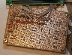
In general I don't recommend starting any project with an enclosure that is smaller than what you can fit a proto version of your project in. But my enclosure supply just about gone, so I'll use what I have. The tekbox from TEKO enclosures. (NOTE: If for some insane reason you decide to emulate this work in progress, buy a tekmar case. It's the same but bigger) Stage 1: Planning (barely) ahead. Since this isn't a masterpiece by the MB gods, I 'm just going to build the control surface on veroboard (protoboard) and hand wire each component. This gives me that added option of making components sit really close to each other without worrying about PCB traces. My veroboards are from RadioShack. They are pretty standard 0.05" spaced holes and have pads on one side. To make sure the control surface would actually fit in the tekox, I created a new part of the pads in Eagle and then placed each component on the grid. My LCD in this picture is from the SparkFun eagle library. I also placed an optional 4 digit 7 segment display and knobs on the layout. (If you can, always place the knobs on encoder layouts. Even if its just a circle. I have at least 3 old projects that I never use because there isn't enough space for knobs and it looks like crap) For all intensive purposes the 4 digit 7 segment display will probably not get populated (but its nice to have the option to put one there). Stage 2: Sizing up the competition As you can see in the picture below, the 1:1 print layout of the control surface fits perfectly in the recess of the top half of the enclosure. The knobs might protrude on either side of the case recess, but I'll just have to live with that. Still not done checking though. I've burned myself enough to know that I'll have to test fit some parts on hand to make sure this is all going to work. After testing the LCD, I realized the SparkFun 16x2 LCD pin out is off by 0.05" but the outside dimension is perfect The SparkFun display was perfect. The Displaytech LCD footprint I used wasn't. I'll adjust the part and retest the fit. In the next version, I've also rotated the swing pot 180 degrees so that I can add the record indicator led next to the shift indicator led. Stage 3: 3D Rendering This step wasn't even remotely necessary. I'm just playing in sketchup with 3D rendering of eagle layouts. I've modified the EagleUp script and created some new models to generate a 3D rendering of this control surface. I originally had every intention of checking this against the enclosure DXF but OKW (TEKO) didn't have one available, so this is what you get. Still makes me happy to look at it. This project is still very much a work in progress. At the time of this writing, I'm still planning the base PCB. If for any reason the MidiBox gods see a train wreck coming, let me know.
-
I've been a huge fan of the MB808 project however, I'm broke in the "I'm married", "whats mine is her's" sort of way :D. As such, my projects are typically small, hacked and require parts I had on hand from before I got married. With the exception of my MB6582. So here I am embarking on my 808 with just overstock and samples. The original MB-808 is far more project than I had in mind. I have a drum machine with all the kits I want, I just need to trigger it. I also want something small and portable to carry around at work while I'm waiting for things to happen. That's where this project begins. Planning the input section I usually start my MIDIBox projects with an idea of what I need to input and output. Using the schematics and some digging in code, I created a DIN map of all my switches and encoders, their original position on the DIN chain, shift register and pin number. I then modified the DIN map to create the most optimal layout in terms of shift register count. This list might not be perfect but it's my best guess. Below is a table of my DIN map. This will drive the creation of the base board and connections. 808 hardware config.pdf Opening the kimono In the spirit of open source I will be sharing everything except the base schematics. This includes the libraries I created to match the PDFs TK has created. I actually like his layouts better for most schematics with some minor exceptions. I used these to help plan the layout of the protoboards and the base including encoder distances based on the knob sizes. This is not my complete Midibox library. I have more parts but its embarrassingly unorganized so here are my most used parts in a library. Among my favorites, are the 40x2 LCD display with the characters to guide placement and the "Waldorf" knobs (which I'm surprised nobody created). I also threw in a Lumex 4 digit 7 segment display (not verified, but close enough). MB.zip