henrygr
-
Posts
220 -
Joined
-
Last visited
Content Type
Profiles
Forums
Blogs
Gallery
Everything posted by henrygr
-
Core Module- Barebone system possible?
henrygr replied to henrygr's topic in Testing/Troubleshooting
Thanks stryd_one.... :o -
I am a bit lost as to what you did. Are you pointing the IR at a moving object in order to measure its movement?
-
Core Module- Barebone system possible?
henrygr replied to henrygr's topic in Testing/Troubleshooting
Oooops. Yes. LCD. Typo. Sorry. Too much LDS when I was younger!! -
I know, I know.... This question probably jas been asked before, and is hidden iin the annals of the forum, but I couldn't the answer after a lengthy search. So in fear of having my hand slapped, here goes. If I have no intention of putting in a LED, is it still necessary to include the parts for it on the core? In advance- sorry, thanks, and no, I won't do it again. Happy X-mas all from Dublin. MP
-
Muse Receptor 2U Rackmount VST Host ...nifty and reliable apparently...
henrygr replied to Artesia's topic in Miscellaneous
Have been working on one for nearloy a year. Though it has to be for live aswell. In January, plan to build the cabinet to house two weighted keyboards. Legs will be electric and retractable. Top and back areas will be made to be modular in that panels can be removed to place in new equipment. All based on 19" standard. Bought the Hammond drawbars some months back, so it will look like a H series Hammond. Plan then to put on a retractable 15" touchscreen. No room for a micrpwave oven though. They come in handy on the road.... Will post design specs over the silly season. Happy Xmas to all while i'm here. And remember..The language of love is music. The language of music is MIDI. Made that up the other day. Thought I'd share it..... ;D -
Ultra, Had a similar problem some years back. I think it is one of these two three things- a Clock speed settings for your RAM in the bios b While you are there, check that the system isn't set to shut down if the CPU hits a rediculously low temperature c remove all CD/DVD roms. Faulty ones will reak havvoc on a system. :)
-
Dual Boot System. Google the terms in CAPS for meaning and instructions -PARTITION the hard drive. You do not necessarily need two actual HDDs, and it is always a good idea to partition anyway to smaller sizes anyway. Reduces your PAGE FILE size, and gives for a more manageable and faster PC. On my own PC, I have my system on one partition, applications on another, samples on another, current projects on another.... you get the picture -Load up XP from the boot CD. It has an option in the boot menu to install XP onto whatever partitions you want. Choose any partition other than your current operating system, preferably as close as posible to the beginning of the physical hard drive (adjacent your current system insatallation would be best) -Google XP DAW OPTIMISATION (DAW=Digital Audio Workstation) to get the best results for recording on your new installation. ;D ;D -Build an MBOX to realise full pleasure of your music making ;D ;D ;D ;D ;D Just a note. When you have the dual boot set up, windows will ask you, just after you power up, which system (your current or your audio) you want to run. Couldn't be easier. Just another note- set up your audio system on the freshly installed OS partition. Will take you about a day your first time doing this. I personally use Partition Magic, but there are lots of apps out there, Happy Splitting, MP
-
A computer solely for Audio work is a "must"....and don't connect it to the internet- ever. That is my experience. The only time I connect it is for XP updates, which is not that often, as I have no security issues. I f i need to download an app or sample, I do so on another PC and network it accross- another tip- never leave a network connection open when working with audio- can cause clicks and pops- fine if you are reworking rice krispies commercials, but otherwise a no no. "A cheap audio pc" ia a bit of an oxymoron. Like "an honest music agent". As a genral rule of thumb though, if the hardware is built for gaming, then it will be ideal for music. I use an nVidia mobo- it even comes with its own ASIO driver for the built in soundcard, although I don't use it as it is onlt 16 bit. Make sure you have tons of good ram, a solid audio card, and a good graphics card to take the weight of its own graphic processing- mine supports dual monitors which is excellent for all those windows in audio apps. Don't forget a KVM switch and network cables!! I built mine into a 2 unit hard case as I travel quite a bit with it (I use VSTi's live) so it is quite durable. Case cost €50 in Maplin. Would post an image for you, but alas, I don't know how. Good luck with the progect.
-
Ooops. Being letting my midibox visits slip. That is one of the few disadvantages of young kids!! The drawbars are from a Kent buily vox continental, c. 1967. I had to totally strip and rebuild them as the carbon in the original slide pots was burnt out. I have since purchased Hammond drawbars on the web, and in January hope to midi-ize them, and put the results here. That will be quite interesting, as I have one set from an M series, and the other set from a H series. Totally different design on both, although I intend to crack the best way to do both. Thanks for the comments. MP ;D
-
Have you placed the proper script into the 'Environment Variables' section. Control panel-System-Advanced-Environment Variables :)
-
All correct. Havr the drawbars pulled and thay are connected allover. It is literally a square grid of busses conneted. One solid circuit. ???? Is there such a thing as a resistive matrix?
-
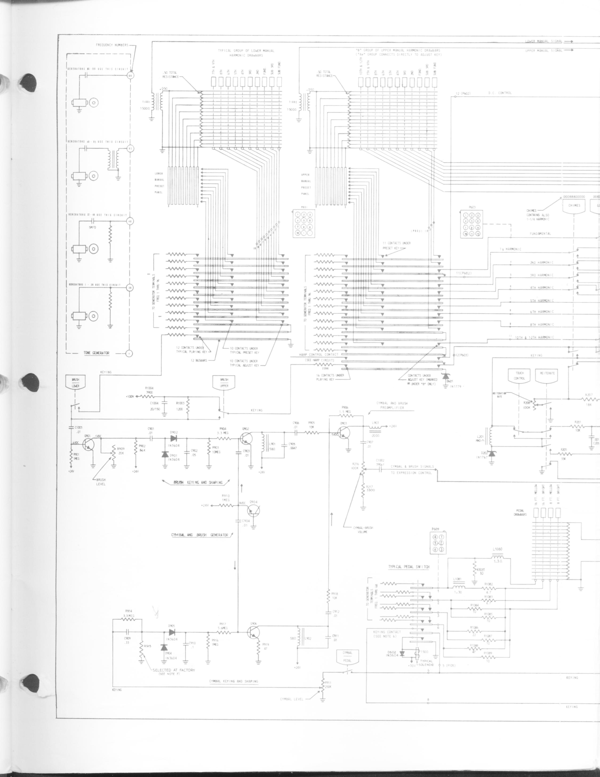
Above is a full page from the Hammond engineers manual. Is this a possible contender for a matrix, or very clever mathematics to possibly get a load of results into one AIN contact?? ??? :o
-
Well. That was the M3 drawbars. To set them break before make, remove the drawbar, and apply a bit of superglue to the inner contact, then apply cling-film, or 'cling-wrap', depending on what side of the globe you reside. Replace the drawbar, and Voila, one perfectly baked break before make. Schematics to the AIN will take a while, but i'll post them....,. Now, the H100 series drawbar. Bizaaaar!!! Different set-up altogether. Take the tram analogy again, but with one contact. Only there is 17 bus bars (1 for ground) set out like below. For the moment, I cannot make heads nor tails of it. Can someone please have a look???

-
Very clever. Theoretically one could run into any amount of combination, but the likelyhood would be quite low. On further examination, a matrix is out os the question, as cutting the bus bars is not an option. I was thinking (last night tring to sleep no doubt) that if I painted one of the contact with an insulating paint, the problem might be solved. Removing oone of the contacts is not an option. Destroyed one of the drawbars last night trying that out.....Just as well I got the M 3 set as well to experiment on... Get well soon stryd, Mark
-
Good and bad news- they cancel each other out. FACT: Hammond drawbars are 'make before break'- you heard it here first. Now that is good news if you have only one. Why? Because you would never need to worry about jitter on your AINS as you pull the drawbar- jitter that would have been caused as the contact slipped between two busses on a 'break before make' switch. Only momentary, but jitter is litter!! (I like that one). With me so far? Now the bad news. When we have two bars (and i will limit the example to two to keep it simple) the situation changes. Lets say we have both our drawbars set at stop tree -go on, close your eyes and imagine playing a barry white song at the controls of a B3. Your solo is coming up. You need to pull out drawbar one to stop four. You hesitate slightly in anticipation of your applause, or because your grandmother is in the front row crying her eyes out, and you know it's really because you reversed over her cat getting to the gig. Even worse, you still have to tell her it's your fault. ::) So you pause. Drawbar one is in a limbo. It sits between stop three and stop four. But that's OK, because contact with bus four is completed, even though the contact with bus three is not yet broken. Good? ;D Well, no actually. Total disaster. >:( What has in fact now happened is that drawbar one has completed a circuit between bus three and four, and as a resut, drawbar two, even though is sitting square on stop three, has also sent a signal to the AIN that it is at stop four. Now, I have simplified the actual end result of this mess. What really would have happened is that the resistive value of busses three and four would have been read in parallel, and god only knows what the result would have been. Poetic justice for killing Marmalade? :o I looked at the mechanism itself. Imagine the drawbar contact like that of a tram touching the electric lines above it. Most trams are equipped with a double contact at the end of, and perpendicular to, a long spring loaded pole. That mean the flow of current is never cut, even when the lines above are split momentarily. When one contact is sitting in the split, the other is still touching a live wire. It would be possible to, if not remove, certainly isolate one of the contacts on the drawbar. The contact piece itself is just a small copper plate with two stud jutting up. My problem is though, it brings me back to the 'break before make' jitter for litter. Is there someway of overcoming this? Would connecting the earth directly to the wie back to the multiplexer be a workaround??? Hope you enjoyed the story.. Mark.
-
Good then I'll go ahead and try it. I would say the bus resistence is as negligable as normal copper wire connection pots together anyway. Just a quick tought though. On the AIN multiplexer, the schematics say not to connect more that eight pots off of the 5v feed in a row. Is it possible to get away with longer. I might post a new thread on this to see if anyone else has succeeded. Thanks stryd, Mark.
-
Thats where confusion has arisen before. The drawbar touches only one bus at any given time. The drawbar is in fact a large one pole 9 way switch, break before make, to put it into modern context. See you kept the sig ;) Mark
-
ADDENDUM: I drew in the contact point, but note that only on bus has contact with a bar at any given time!!!!
-
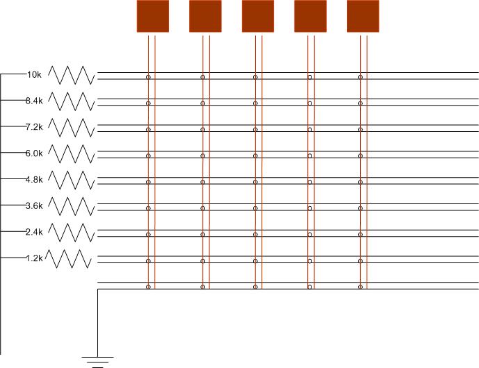
OK No point taking photos as the unit is well sealed. I did a diagram though. The red lines with the red boxes indicate drawbars- just in case you were wondering, or being otherwise distracted by Barry White. The cross lines are where the contact busses run. I represents five drawbars, however they run for twenty two, The resistors in the diagram are my idea to midify it. I left out that the signal back to the DIN runs from the drawbar. I propose to break up the busses every eight drawbars and run a set of resistors again. Would this be necessary do you think, as Iwant to leave the unit as much as in tact as possible.

-
Not when you put it like that, no. That sounds like something that should belong on a porn site..... :P
-
I know barry white- he saved my life!!! I want the mp3 of you singing the drawbar song. Maybe we could choreograph a dance too. Could take off... You heard it here first. ;D
-
Mmmm. Could you post an mp3 of that?!..... :-X
-
I took delivery yesterday ;D ;D Will post a few photos. Yes it is eight stops per drawbar- switch style, not potentiometer. Each stop in in a series of stops is fed by the same current. It is also split in two. So from above, it looks like a matrix of 8 by 22 switches. If I am not mistaken a scan matrix would require soldering a diode at each point. Iwant to do as little damage to the original piece as possible. So I was thinking of feeding each of the eight point, or stops, on the drawbars with the relative currnent of a 10k slide pot. Ie resistor of 1.2k at stop one, 2.4 at stop 2 etc. I have seen somewhere on the web (http://www.geocities.com/JDPetkov/Hardware/B4ce/B4ce.htm, here in fact. It was a discussion around here a while back that put me onto him) that the correct wiring was 8 by 1.2 resistors in parallel. This is wrong. I think he made his assumpyions before seeing the unit. He assumed that as the drawbar was pulled out, contact made with previous stops was maintained, and that resistors in parallel would achieve a result. (This is a common misconception of Hamond drawbars) Will get the Nokia busy and take some snaps. FYI This also arrived yesterday-http://cgi.ebay.ie/ws/eBayISAPI.dll?ViewItem&ih=004&item=140005371147&rd=1&sspagename=STRK%3AMEWN%3AIT&rd=1 ;D ;D
-
I bought one on ebay just a few days ago as a result of seeing this thread. I think I will keep it to do the keyboard shortcut thing instead of setting it up as an mbox module. I use a PC whn I play live, so I will look into what can be produced. How did you get on with the original mod? Also. forget the grocery stores. Filling station keyboards have leds built into the keys. Trust Exxon Mobil to have the money!!! MP
-
That was my main thought. It would also require less circuitry. And then, when I hear you say it stryd_one, I know it is right.... :)