napierzaza
-
Posts
442 -
Joined
-
Last visited
Content Type
Profiles
Forums
Blogs
Gallery
Everything posted by napierzaza
-
I'm in Montreal! I don't know where the frappr map is
-
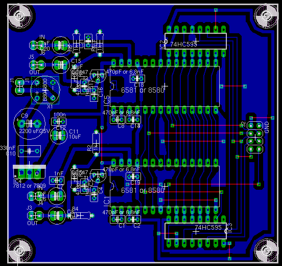
I'm developing a neww pcb for the OPL3 Module
napierzaza replied to selfservice's topic in MIDIbox FM
Wow, that's really nice looking. So you just hammered out a PCB for yourself, including a PCB for the PSU? My God, I wonder sometimes where you guys learned all this stuff and got all the equipment, but then again I'm just jealous. Also I was going to say you shouldn't solder the ICs, but you clearly know what you're doing! -
I'd certainly be open to suggestions about the track widths. I tried to make them as thick as they could really muster within the available space. If there's some rule or suggestions you have about that I'm all ears. Well I certainly hope this PCB works out well enough too! We'll see if I can ever muster this project to go further than concept :-\
-
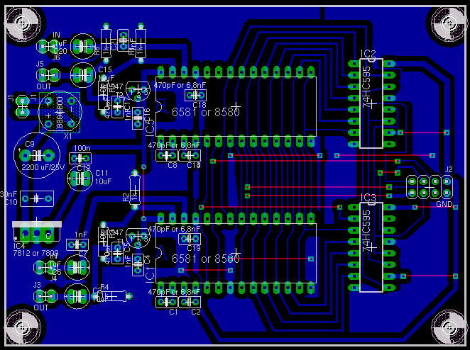
For little good reason I made a new one that is a little wider and a little shorter. This seems a little better to me conceptually, I guess I should not have followed Wilba's so closely as now it's much closer to the origal positioning. As far as I can tell it would work just as well as the other one, but it's just a different foorprint. mbhp_sid_DoubleALT.brd 2.zip mbhp_sid_DoubleALT.brd 2.zip

-
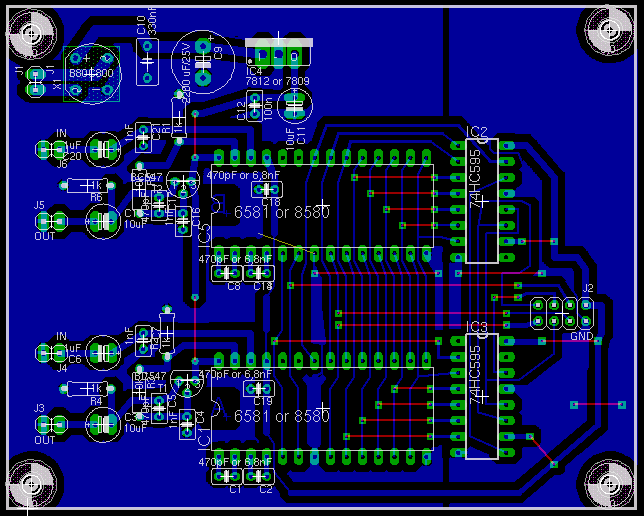
Thanks for the suggestions, for some reason I didn't really realize that or thought it was better to make way too many jumpers. I have incorporated your design suggestions. Please tell me what you think. I suppose I will be trying to figure out how to etch PCBs for this one. I actually have gathered the two 6851s so other than PCB I have all the diifficult stuff. mbhp_sid_Double.brd.zip mbhp_sid_Double.brd.zip

-
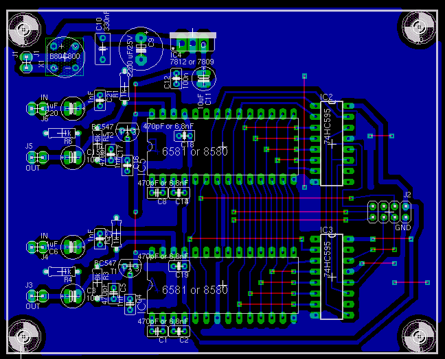
If anyone is interested here is the final version of the board as per Wilba's suggestions, plus several fixes which were previously unseen. mbhp_sid_Double.brd.zip mbhp_sid_Double.brd.zip

-
Does the PIC Burner burn these new pics? If so, at what voltage and program?
-
Yes, that's exactly what I meant, I was wondering whether I would have to cut the pin that it goes to on the core and reroute it, or whether I can just jumper it and have bother connected. It's just that I forsee that I'll be using a smash board for this (for the core), making it difficult to remove any pins of sort. I guess I'll have to punch up a proto board.
-
Do I have to modify the core anymore than a jumper? Can that pin (above the GND) still remain attached to the J2 pin as it is presently? Or do I have to just leave it disconnected and make a new jumper pin to the new pin described?
-
To anyone who is interested, here's my double SID board, all within a freeware EAGLE board. One problem I had was what to put on the pin right above the GND pin of the J2. It looks like on your board you actually attached the second SID's (the top one on mine) 8th pin to a funny pin on the PIC. What I mean by that is that you connected pin 8 of the SID to 27 of the PIC, which isn't available through that connector. Also I haven't totally checked it over so no guarantees as to whether it might work. mbhp_sid_v3+double.brd.zip mbhp_sid_v3+double.brd.zip
-
The more I look at this the more I realize it's particularly infeasible for a single sided board. It appears as if your version has a lot more connecting the two than just the j2. I suppose because you're only using 2 registers. I might just make a more simple version where there's two of Thorsten's model on one board. But I would like to optimize the registers as you have done.
-
Whoa, That's some very cool stuff there, I'm going to copy as much as I can indeed! It's just a shame considering that it's in a different program than EAGLE, and also designed for people who can afford that sort of thing. I might as well tell you that your multi SID is really really amazing! Did you know it was posted on hackaday.com?
-
Considering that the MIDIBOX SID v2 will potentially have the ability to connect 2 SID modules to one core, I was wondering how this would be achieved? Would they share the same J2 connection? I'm planning on making a PCB with two of the modules together, and wanted to know what I should amalgamate and what I shouldn't.
-
Model number: sh012a model
-
here is a schematic of the ref voltage circuit. I figure that if it's constantly holding at about 3 - 3.1 volts that there is something wrong, but am unsure about what, in this circuit, that may be. That is to say what specifically would have to break in order for it to not work. I'm really not certain what the issue is but it appears as if it might be in the feeback section (431 & 4n35). I've tried 3 different 431s and they only offer slightly different results. I've also tried 3 different octocouplers with slightly different results.

-
I've read that paper and it really helped me understand the circuit. Looks like a really standard flyback circuit using mostly the standard parts. tl431 as a reference voltage (hooked into a 4n35). c2553 as a switch rectifier diode as a supply side rectifier. BC337 on the high voltage side, being used for... ?
-
Okay, It seems to be working at least as well as the BC549 did, but it's still giving 3volts whether I have the original resistor in the the 431 circuit or the newer one I picked out. However it appears to change voltage from 3v volts to 3.08 volts if I change the pot setting. This is somewhat perplexing!
-
I put in the BC337, see if it outputs the right V. Thanks for the offer prof, but I'm in Canada actually.
-
datasheet mXyzqszz.pdf mXyzqszz.pdf
-
MIDIbox of the Week (MIDIbox FM of Napierzaza)
napierzaza replied to napierzaza's topic in MIDIbox of the Week
I'm surprised my awkward looking FM made it to the Midibox of the week. -
Crap, I have one, but I think it's reserved for one of my future midibox projects. What if I had a BC549? EDIT: Okay, now it's working with no noise. It's now functioning at 3v which is odd. I recall it going around 4-5 previously (even the bad transistor replacement). I think it might be a reference voltage issue, but I swapped that out and no such luck. Do you think this is this still a transistor issue? I believe that is at least near the base that the 431 can output (2.5 I think).
-
Forgot to post these datasheets datasheet.pdf MPSA14.pdf datasheet.pdf MPSA14.pdf
-
Okay, I need your help again. I, somewhat, got it working again! Basically the info you gave me allowed me to check if the different ICs were broken or not. Some were, but it still didn't work. I then realized there was a small NPN transistor in the circuit I didn't check yet. It was a 2SC3203 NPN Transistor. So I realized I had a lot of MPSA13s lying around and they had the same pinout and the same (NPN) config. So I swapped them both and bang (not literally) the PSU came on giving its old voltage that it used to. This was good except that now it gives off a high pitched whine (very audible) all the time and it certainly didn't do that before. Is this because of the transistor?
-
Well my mouser order cost was increased by about 50% because of shipping,taxes,holding fees. If you have any specific recommendations for a place that might sell transformers, or better yet a linear 12+,12-,and 5+ PSU I'll check it out. But even just shipping to Canada really slagged my project. Personally I really don't want to build a PSU, I'm hoping that the one I fix will be easier, but if I could just buy one for a decent price I would.
-
_IF_ it didn't cost as much as it does to ship such a PSU.