m00dawg
-
Posts
1,404 -
Joined
-
Last visited
-
Days Won
16
Content Type
Profiles
Forums
Blogs
Gallery
Everything posted by m00dawg
-
I realized that it's not immediately apparently what I'm talking about :) So here's a few images. So my question is, are the two boards electrically equivalent (will they filter out the same noise, etc.)?
-
Multi-Tap Transformers Versus Voltage Regulators?
m00dawg replied to m00dawg's topic in Design Concepts
So let me preface by saying I tried to translate that page to English and Google sort of failed on that one :) So I apologize if it's already answered on the provided links: Why did you opt for so many 1000uF capacitors, over, say, few larger ones? I know that electrolytics can be slower to react than other caps (which means that you still end up with some wobble, hence the need for additional caps) so is it just smoothing it out further? Not that there's anything wrong with more caps, mind you! :) Are those vertical red rectangles (on the primary side of the xformer) MOVs? Finally, what dual primary and secondaries over, say, a center-tapped transformer? Reason I ask is that you can get 10V/5V AC with a center-tap, making life better for your 7805 but beyond that, I don't know the benefits of a center versus dual primary/secondary transformer. -
Multi-Tap Transformers Versus Voltage Regulators?
m00dawg replied to m00dawg's topic in Design Concepts
I believe you :) I've seen that number used before. As for the Java applet thinger, Smash has an AC->DC graph thing that's pretty neat, but it's probably not what lylehaze was talking about. Smash's just shows the current in various states after rectifying, filtering, etc. Still, it's a really nice site. Unfortunately, I don't have the link to that one either :) -
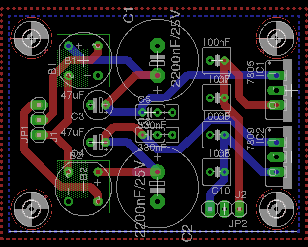
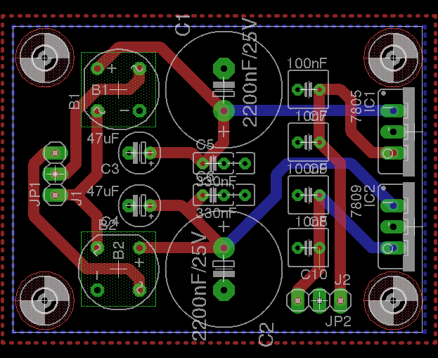
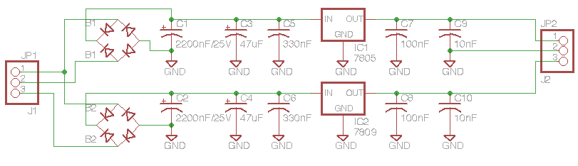
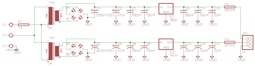
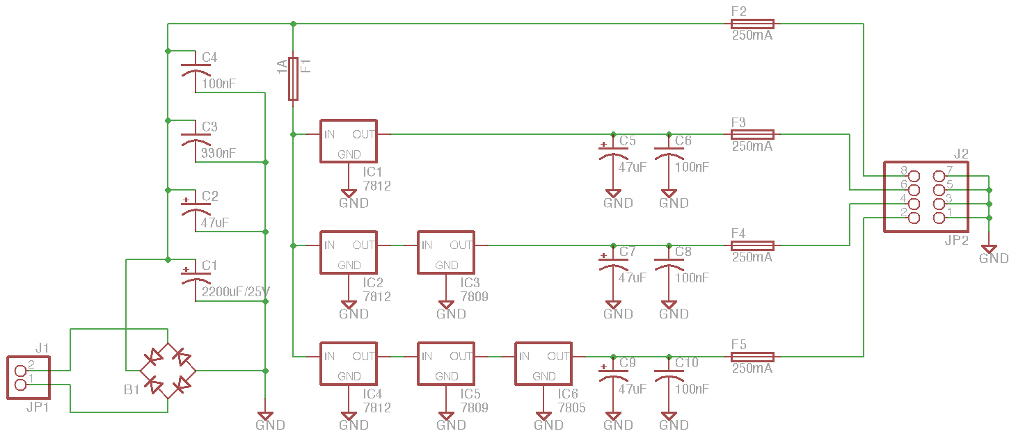
So this sort of carries on with another post of mine about building a PSU suitable for the MB-SID. I thought I would post a new topic, however, since the question doesn't quite relate. The design of my new powerboard (which using a center-tapped transformer) is coming along nicely but I'm trying to conserve as much space as possible on my board. As a result, I have had to place my capacitors in interesting configurations. What I was wondering was how much does the order of the capacitors matter and do they need to be in parallel (one after another) or simply on the same wire to have the same smoothing/filtering affect? I know that connecting capacitors in parallel increases the total capacitance, but I'm more concerned about making sure HF noise doesn't get through and I'm not sure if there's tricks or pitfalls to doing it a certain way. Based upon my searching and knowledge, I always assumed you go from big to small, so, say, 2200uF -> 47uF -> 330nF -> 100nF -> 10nF. Each one has less of a capacitance, but because they are made of different materials, they have different characteristics. I know the eletrolytics don't filter out HF noise, but are obviously good for smoothing out the AC ripples. The smaller ones can then filter out the HF noise. But can the sequence be re-arranged to produce the same affect (such as 2200uF -> 330nF -> 47uF .... ). And can I do something like have my +V coming from my rectifier and have it fan out, making sort of a star, to each capacitor instead of routing the wire to each of them individually? I assumed no :) Doing either of these means I can save space and probably avoid a two layer board (meaning the bottom can just be a ground plane). But before I make a big mistake, I wanted to make sure I knew more of what I was getting into :) Also I apologize if this is already on the forums. After some lengthy searching, I didn't come up with an answer to either of the above questions.
-
Multi-Tap Transformers Versus Voltage Regulators?
m00dawg replied to m00dawg's topic in Design Concepts
Yes that does indeed make a bit more sense! I knew transformers were measured in RMS, but I never thought to actually look up what that meant in terms of this particular instance :) So based upon your information, and the magic number (1.414) that stryd_one provided, it looks like I should be good to go with a 10V center-tapped transformer. If I went with a 12V, that would be almost 17VDC I would be feeding the 7809, which seems a bit high I think :) Thanks for everyone's help! I'm still working on the power board design and how to cram all this inside a power-brick style case. And I still need to order the parts. But I'll try to keep everyone posted as I progress! Seems like something like this would be worlds better than a C64 power supply and it's an excuse to build something else :) -
Multi-Tap Transformers Versus Voltage Regulators?
m00dawg replied to m00dawg's topic in Design Concepts
Turns out I couldn't sleep. Too excited about all this stuff :) So I'll venture a reply... Let's not get carried away now :) Transformers are somewhat new to me, although I've done a few power boards at this point using a single wal-wart transformers. Absolutely. Actually, the full steps should be: AC -> Rectify -> Smooth - > Regulate -> Smooth -> DC The values of the capacitors used for the smoothing seem to be magic :) I use 2200uF, 330nF before the regulator and 110nF, 10nF after. That basically covers most of the types of capacitors and should help filter out low and high frequency noise. I'll point out here that I'm no expert, however :) Those values were grabbed from the forums, experimentation, and just because I had extra capacitors I wasn't using at the time. The current board I'm using (which is using chained rectifiers) does seem very quiet with this setup. I would say, however, that the average person wanting to make an MB-SID should just try to grab a C64 PSU :) Now that's the part I've been confused about because I have heard it both ways. Rectifying AC actually causes loss of voltage, but the input AC voltage could be more than whatever is labelled depending on load. I've seen multiple equations (trying to find a good one to use as a base), but there's a PDF I found from Hammond's site (which I grabbed from Mouser while looking at transformers) that offers some numbers: http://www.hammondmfg.com/pdf/5c007.pdf I assume there is a relationship here between the rated current of the transformer and the current I'm actually using. So, I'm just guessing here, if I get a 12V transformer that can handle, say, 3 amps, I'm guessing it will actually give me more than 12VDC once I rectify it assuming I'm only using, say, 250mA. *shrug*. The one thing I'm still curious about is how multi-tap secondaries work in this case. If I have 2 6V secondaries, I'm curious as to if I can combine them into 12V *and* tap off one to give me 6V as well. Basically, I'm wondering if I can use a similar configuration when using multiple-secondaries as when using a center-tap. I haven't quite found good information on that yet. -
Multi-Tap Transformers Versus Voltage Regulators?
m00dawg replied to m00dawg's topic in Design Concepts
Actually, I've chained them before. It does get hot and requires a big heatsink but it works well. You might want to add more smoothing capacitors after regulation though. As for this project, I think I have things figured out: I'm going to use a center-tap 12VAC transformer. That will give me +12 and +6, which I can smooth and rectify separately to give me +9 and +5DC. Regulating +12 down to 9+ is a bit of a step, but I think it should be fine since it will draw less current than the +5VDC. I opted to go with 12/6 over, say, 10/5 to allow more headroom. Though, to be fair, I should probably figure out the math to back that up :) I've heard conflicting opinions about how much AC voltage headroom one needs to feed to regulators so I still need to research a bit more on that. Either way, this has certainly simplified my design! I did have to remove the transformer from my Eagle design, however. I couldn't find a center-tap transformer object in Eagle. Even if I did, the board would have been bigger than it needed to be I think. So I'm just going to be a chassis-mount transformer and screw that into whatever case I end up using. I've got the board already designed but it's getting late so I'll send that out perhaps tomorrow. Thanks for all the help everyone! Will keep you posted! -
Multi-Tap Transformers Versus Voltage Regulators?
m00dawg replied to m00dawg's topic in Design Concepts
:P I hate replying to myself but I just had a thought...the MB-6582 uses the 9VAC and 5DC connections of the C64 right? So, all I really need to provide is a nice, smooth, 9VAC and 5DC. Thus, I could use a single 9VAC transformer, smooth that a bit perhaps, and supply it as-is to the MB-6852. Then I could regulate that down to 5VDC. That regulator might get a bit hot, but at least this way there's only one of them and no having to do weird regulator chaining or anything like that. Thoughts? -
Multi-Tap Transformers Versus Voltage Regulators?
m00dawg replied to m00dawg's topic in Design Concepts
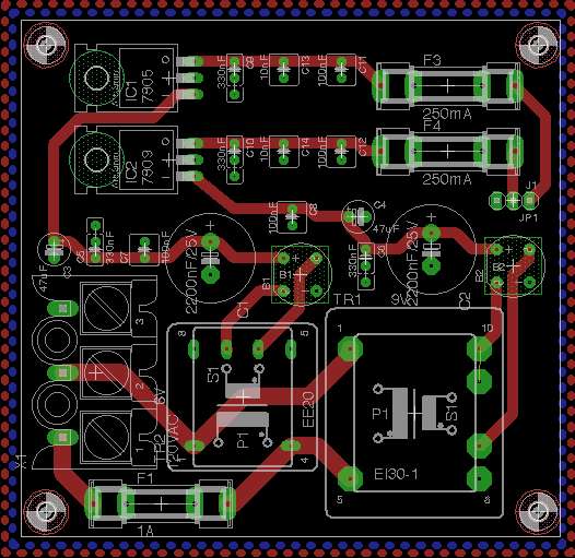
Dunno if it will help much, but here's my current board design. I just threw it together for funzies so I don't expect it to be a final product or anything, but perhaps it might help with the conversation. Actually, it's already flawed since it sounds like I'll need bigger fuses (I only put 250mA). powerboard-xformers.zip powerboard-xformers.zip -
Multi-Tap Transformers Versus Voltage Regulators?
m00dawg replied to m00dawg's topic in Design Concepts
Thanks both! @Futureman: The current draw is higher than I originally expected, though I did find some PCB mount transformers that might work (they may even be toroidal transformers). The problem there is that they take up quite a bit of room which makes printing a PCB expensive, not including the fact that it's easy to run into the board limitations of the free version of Eagle :/ At least, that's when using two transformers. If I can get it down to one, I shouldn't have a problem. @lylehaze Oh yes, I'm aware regulators are still needed, although the input voltage is a but confusing I've found. 9VAC can result in +/- 9VDC if I'm not mistaken, depending on load, actual input voltage, and the fact that converting AC to DC gives you slightly more volts? I got that by consolidating all the information I've found from other posts so I'm not sure if that's 100% correct. In other words, I'm not sure if I should get a 9V/5V transformer, or a 11V/7V one. The higher one shouldn't hurt anything, of course, if the regulators are sufficiently cooled. Either way, my plan was to have a 7809 and 7805 in my own design. The difference is that they won't be in series. So the 7809 won't be supplying the 7805. Instead, they will use different rectified voltages from the multi-tap or multiple transformers. The fact that multiple voltage output transformers are hard to find is a bit concerning though :/ Mouser has a few options, but they are either too big or too small. I usually use Allied Electronics because their parts get to my doorstep in sometimes the next day, but they have even fewer choices as far as transformers are concerned. I suppose if I can't find a multi-tap, I can just go back to supplying both regulators with 11V, but that's a lot of voltage for the 7805 to handle. That means I'd have to go back to putting them in series and that just seems a bit gacky :) Connecting it all together is another issue. My plan is to use a power supply chord and wire it up that way. But since I'm dealing with mains, I have a feeling I'll need beefier wiring on that side and I haven't done that before. Heck, I'm not sure I'm even wiring the thing right in my schematic :) Correct me if I am wrong, but the AC fuse goes on the positive AC line and I would ground the board to the 3rd grounding pin of the AC cable? -
It seems like most people here tend to either use C64 power supplies or build their own using a wallwart and voltage regulators with some filtering capacitor magic for powering the MBSID. I'm ok with that approach (I've design a few of my own this way) but I was curious - has anyone used multi-tap transformers? Someone at work told me you can buy a 120V transformer that can produce multiple AC outputs (9 and 5, for instance). I'm thinking of using that to build my own power-brick. The idea is to have it generate +9 and +5 DC for the MB-6582 board. I was thinking of making this into an external power brick of sorts, but one that sucks much less than that terrible C64 PSU (yes, it works great until the damn thing breaks and you're SOL). Trouble is, I can't seem to find these things anywhere. I've looked at Allied and Mouser and I'm a bit confused with getting the right part. I've seen multiple ones that have multiple outputs, but they are all the same output? Anyways I'm a bit confused and if anyone knows what to look for or where to find these, that would be awesome! On an aside, I'm also having trouble finding heatsinks online that match what is in EAGLE. My original power design used regulators with a huge heatsink on top. My prototype just used one I stole from a motherboard, but I can't seem to find anything close to that on EAGLE. What do other people do? Just measure out the holes on the heatsink and match it to EAGLE or? All that said, I'd be happy to share my design once it is complete I know a few designs are out in the wild, but most seem to go the vreg route, and also seem to leave out fuses in their designs (something I'm definitely going to be including).
-
Holy crap that sounds AMAZING! Alas, I was only able to find crappy YouTubes and NSF files (no MP3s from the real thing) but it certainly gets the point across. Damn you Nintendo of America for screwing me over yet again! Anyways thanks for the explanation skrasms!
-
Thought cross my mind, but if I did that, I'd probably move the regulator to the power board itself, at least for the "main" CORE module. I still might do that, though. Trying to figure out the best way to approach the whole thing :) Unfortunately, I don't have a metal case - at least not yet, so I think the sink is the best way to go.
-
Thanks Stryd! I did indeed find quite a selection at my electronics dealer. I think I'll buy a few of these at least to have as well as look at some heatsinks for the SIDs (saw a few threads related to that while trying to find an answer to my regulator heatsinks). As for the power, I'm supplying CORE with 9V (regulated). I'm thinking of using a multi-tap transformer at some point, but for now I'm stepping the voltage down using regulators. Now, of course, the regs on my power board did get hot, so I put them under a large heatsink I grabbed from a busted motherboard. So they, plus the 7809's on the SIDs (I'm supplying them with a regulated 12VDC by the way) are good. The 7805 on CORE, however, has gotten up around 60C after about an hour. Definitely too hot to comfortably touch. I have an LCD and a few control surface items, plus the +5V from CORE is also going two SIDs (I figured that was easier to do for now then using yet another regulator at least for now). I made a pretty ugly attempt at mounting a fan, and while it helps cool the big heatsink, it doesn't help much for the 7805 on CORE, which is too far out of the way to get any wind I think.
-
In my current SID design, I am still using the 7805 regulator for the CORE module and I'm trying to figure out ways to cool the thing down. I may eventually put the 7805 on my main power board so I can stick a gigantic heatsink on it (to at least power the main CORE module since it's driving all the LEDs and such, or will be once I"m done anyway). Until that time, however, does anyone have any suggestions on a small heatsink I can put on it? I'm using Smash's CORE board if that helps. Thanks a ton!
-
Any idea when 2.0 will be out? Sounds like it has some awesome features! I've ALMOST purchased one, but have opted to hold off until I can fix up my NES (the usual bent cartridge pin connector and I think I have a bad cap somewhere along the video out). That said, I don't think the US version had the audio outs on the carts. I could be wrong since it has been some-time since I have looked into that sort of thing. That said, while it may be a Japanese only thing, a few choice carts had some crazy add-ons. One had an FM synthesis chip built-in (I forget which game that was though).
-
Hahaha well good to know for the future :) Wonder why they didn't put a link to that on their Eagle How-To *shrug*
-
Just FYI to the MySpace haters out there, you can get the song from iTunes. Yes, it's another evil, and yes you have to pay a $0.99, but I'd rather do that than get a MySpace account. I've tried using it before. The pain is far too great. That said, awesome song and well worth the $0.99 I had to pay to not download it for free :) The SID sounds beautiful in that song!
-
Here's another update. Now with fuses! I'm not quite sure if I might be overdoing it here, at least for the rectified DC output since I have both a 1A and 250mA fuse. I did that because all of the other DC outputs jump off that one but I am also supplying it as a raw output (in case another component already has a voltage regulator for instance. powerboard-alt.zip
-
Yep :) batchpcb.com (which is the fab placed I used) does have a nice how-to on setting things up correctly in Eagle, but it doesn't include the design rules - rather it includes things like how to properly silkscreen the thing and output it into the proper machine files they use. Oh well :)
-
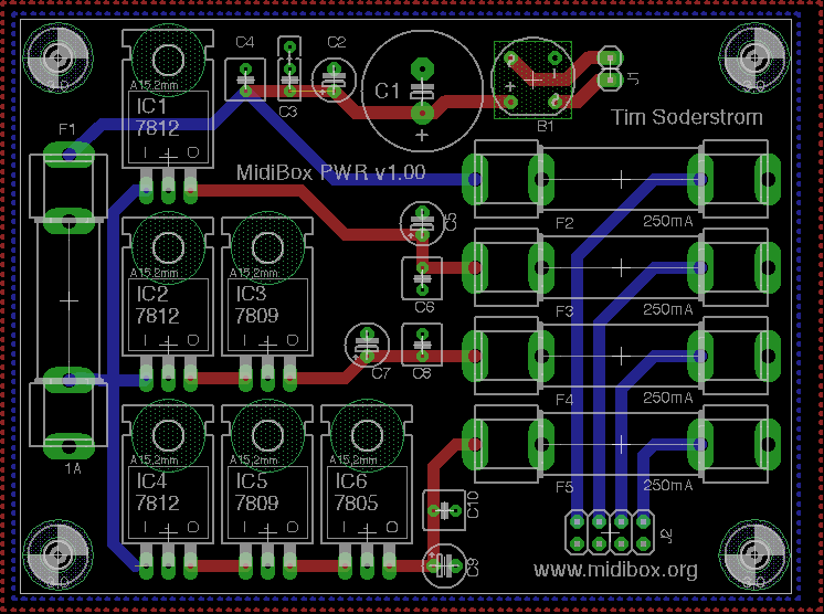
Well, I got my boards in! I stuffed one tonight with chips and everything is good to go! I haven't tested the external bank yet (not really high in my to-do at the moment) and I did run into an issue with the ground plan. Though Eagle didn't show it, there's a gap where two wire tracks actually split the plane due to their close proximity to each other. Doh! So I had to run a wire from the ground pin to one of the IC sockets so re-connect the ground-plane to, well, ground :) As a result, I'm going to update the board layout. I'm thinking about rotating the chips horizontally since I think that will actually simplify wiring. I plan on posting pictures at some point as well. In any case, if anyone wants the board layout and/or schematic, I'd be happy to provide it! I'll probably posting an update as well once I have time to play around with it again (I have some other boards I need to make for other parts of the synth at the moment). Some other MidiBoxers have been making their own boards as well, so there's plenty of options for people wanting boards of their own!
-
Use 40 pin connectors on DIN and DOUT boards?
m00dawg replied to jimhenry's topic in Design Concepts
You can probably just get a longer cable too and cut the wires towards the middle to length or something. But I agree, I like the 10-pins better, but not for any good reason (I think they look better :P). -
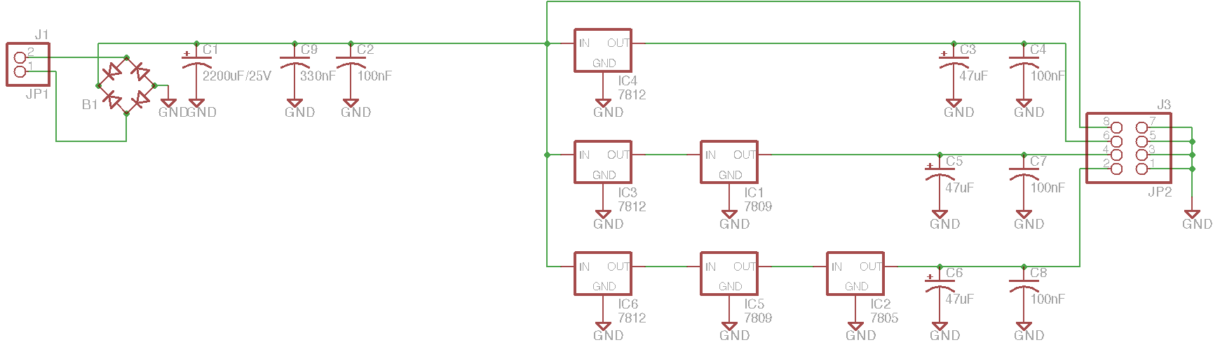
So here's an update. I dropped the jumper idea in this one since it seemed more trouble than it was worth. So this design offers 12, 9 and 5 and, thus, requires the use of a 14VAC input. I also did away with sharing the voltage regulators, so each output has it's own regulators in series. I get the feeling I might need more filter caps, but am still trying to read up on those sorts of things. Anyways, enjoy :) powerboard-alt.zip
-
Yes, and perhaps also a disclaimer since these boards are much less "official" than those of SmashTV and ucapps. Nonetheless, we all seem to be doing similar things and, instead of reinventing the wheel every time, seems like we could really use a Wiki, or some sort of community driven system, to our advantage.
-
Actually, on the note of the voltage regulators getting hot, one alternative would be to use multiple voltage regulators for each "rail". So, for the +5V, I would have 3 dedicated just to the +5V (a 7812, 7809, and 7805). The +9V would then have it's own 7812 and 7809. A bit wasteful, and somewhat more expensive space and money-wise, but that might avoid pumping a huge amount of current through a shared 7812. *shrug*