m00dawg
-
Posts
1,404 -
Joined
-
Last visited
-
Days Won
16
Content Type
Profiles
Forums
Blogs
Gallery
Everything posted by m00dawg
-
Multi-Tap Transformers Versus Voltage Regulators?
m00dawg replied to m00dawg's topic in Design Concepts
Hmm...that's interesting you mention that because the problem I have been having with this design is that, the more power it pulls, the less voltage I get. I also get a lot of AC hum. Seems to me that crazy ground explanation you gave previously may be panning out? I'm not sure though. As for using two bridges - I tried that and failed :) I was never able to get 6V and 12V (it was just one or the other) when using two bridges. I have no problem using that approach, but how do I hook those bridges up with the xformer? Can you even do full-wave rectification this way? Do they both share the same outer-tap (which would be GND) or? I tried multiple times doing it this way so any help in that regard would be appreciated. -
Haha I wouldn't call it the best option by any means :) Just another option. Some people really jones for the C64 PSU, some prefer wall-warts - it's all about preference and choice I figure.
-
One suggestion someone pointed out to me while I was thinking about these ideas myself. If you move all the power stuff outside of the PT-10 case, the only heat being generated that much be of significance would be the SIDs. All other heat would be outside the box and you can deal with it appropriately (big-ass heatsink, metal cage if you want - whatever) and would have the space to do it. That's the route I am going - namely building my own "power brick" to supply 9V and 5V to MB6582 directly. Plus, you can properly fuse the inputs, etc. It's more work, but I'd tend to recommend that option if you don't/can't bother with a C64 PSU.
-
Multi-Tap Transformers Versus Voltage Regulators?
m00dawg replied to m00dawg's topic in Design Concepts
Ok so I did another check and the voltage is about 4.9V with 2 SIDs, 1 PIC, LCD, and 8 Banksticks. Later today, I am slowly going to start adding more PICs and SIDs and see how things go. I did play around with it in it's current state and it worked like a champ. Filters work on the SIDs (*whew*) and no skipped notes or anything like that and it's fairly quiet. There's some hiss here and there (it's barely noticeable) but no hum. The heatsink on the 7509 and 7809 seems to work well. While I still want to figure out the center-tap stuff, but since I have to wait a while in order to get access to an o-scope, I think I may get a 9V transformer instead of my current 12V and go from there. Again, will keep anyone that happens to care posted :) Thanks again for all the help on this one! -
Multi-Tap Transformers Versus Voltage Regulators?
m00dawg replied to m00dawg's topic in Design Concepts
Oh I should add the voltage drop isn't enough to make things not work. It's around 4.5-4.9 or so I think (but I'll need to try that test again this evening to double-check that). I haven't added the BankSticks back into the equation, though, but I did stuff another PIC without much difference. The LCD backlight remains quite bright, which is a good sign. Just not sure why I'm not closer to 5V on the 5V rail. The 9V rail dropped only very slightly - from 9.02V to 9.00V. -
Multi-Tap Transformers Versus Voltage Regulators?
m00dawg replied to m00dawg's topic in Design Concepts
I sort of discounted that because of the heated debate on the forums about whether or not that's a good idea for the MB-SID stuff (due to the fact that the SID is analog and switching supplies tend to spew RF). I've seen people say they work well, though, but it's always been after ignoring the pushback of people on the forums :) Sort of makes sense I guess. The SID uses 5V too so it seems like it certainly can't help noise, but heck I'm willing to give things a shot :) Part of the point of this project is to make something that's reproduceable for others who can't or don't want to use a busted ass C64 PSU for powering their beautiful SIDs. On a related note, I swapped out the regulators of my old power board so I could output 9V and 5V from the same taps. It actually works pretty well, although I'm still seeing a voltage drop in proportion to load (it's just not as big). I think it's specific to the MB-6582 board, the cable to do, or something along those lines. I need to try it again, but I checked the voltages on the board with a PIC and 2 SIDs stuffed and was getting like a lower voltage reading from the board than I was when reading it off my power board. So I think there is still some grounding weirdless. Although, I don't hear ANY AC hum, so that's a good sign. -
Multi-Tap Transformers Versus Voltage Regulators?
m00dawg replied to m00dawg's topic in Design Concepts
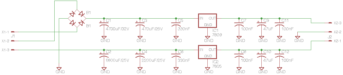
Wish I could find a multi-tap transformer that did offer +9 and +5 though. Either way, since some of the schematics are a bit old and buried in previous pages, here's the latest and greatest which may help the conversation a bit. Note that the center tap is X1-3. This was to make it easier to route the wires on the board itself. @MRE Good news! I should be able to get my hands on an O-scope! The bad news is that it may be a few weeks out :P So until then I'm just going to use a fat heatsink on the 7805 and build a more conventional setup. @seppoman I'd be ok doing half wave rectification but where does the negative come from? The other outer tap or? Thanks everyone for all the help! I dunno about you guys, but this has been an enlightening learning experience. -
Multi-Tap Transformers Versus Voltage Regulators?
m00dawg replied to m00dawg's topic in Design Concepts
Yep, I actually do have those. In fact, they are right in line what you suggest (.33uF and .1uF) on either side of each regulator. Still am hearing a good bit of hum though. I haven't heard back about borrowing and o-scope but your suggestions have been quite helpful! Hopefully I can track one of these guys down and put your suggestions into practice. In the interim, I may just build a more standard setup, or modify an existing design I already have built so that I can at least work on testing my MB-6582 while I wait. Of course, I'll keep everyone posted on the results! -
Multi-Tap Transformers Versus Voltage Regulators?
m00dawg replied to m00dawg's topic in Design Concepts
Magic :) Well actually no, I did this in part because it seemed like more capacitance was needed on the 5V side. I thought it might be half-wave though - you're thinking it's more like quarter-wave or something like that? Basically, I knew 2200uF and 330uF were good pairs for a standard full-wave rectified setup, so I basically assumed I needed to at least double it. So, I got the biggest reasonably inexpensive cap that would still fit on a reasonably sized board - so the pair ended up being 6800uF and 2200uF. That's the idea anyway. For my current board, I used a 6800uF but still have the 330uF in place. I can switch that out, but it sounds like that still may not be enough? As for your previous question, alas, I do not have an oscope, but I might know someone I can borrow one from. I'll go ahead and check on that and see if that might be doable. -
Multi-Tap Transformers Versus Voltage Regulators?
m00dawg replied to m00dawg's topic in Design Concepts
Thanks MRE! That's been most helpful, and I see what you're getting at. In fact, it makes a lot of sense. When I had smaller caps on the 5V side, when the load was high enough, I started to see the 5V LED start to flicker. I thought it might be because of AC, but if the regulator is actually shutting down, that could explain things. Using a diode on the 5V side has been discussed. I thought about putting one on the schematic, but in the circuit simulator, it didn't seem to make much difference. It's easy to add in though so I'll see if Radio Shack has one or just order a few of these guys. I think there is AC hum leaking through. The SID testtone app outputs a noticeable hum. If this was coming from the 5V supply, I assume it will still hum right? As for the caps, my design called for one 6800uF and one 2200uF cap on the 5V before the regulator. Do you think that isn't enough? The simulator said it might be but, then again, it's a simple app so I just sort of went with it. I originally had a 2200uF and 47uF and that seemed to be much too low. If I were to take a guess, I'm assuming your suggestion is to just use the outer taps, fully regulate and smooth that into DC and feed it to the two regulators directly? I was hoping to build something more heat efficient but now I'm thinking that this approach may be the best option. Thanks again for all the help and insight! -
Multi-Tap Transformers Versus Voltage Regulators?
m00dawg replied to m00dawg's topic in Design Concepts
No disregard needed - there was some additional information not in that previous six pages :) So it was a good read, or, if nothing else, a nice refresher. Seems like the regulators are getting plenty of power from the xformer. You made me think of a good point, though - I haven't checked the voltages on the outer and center taps when I notice the drop on DC voltage. I would assume it would be normal or the regulators would stop providing power, but it never hurts to check! :) -
Multi-Tap Transformers Versus Voltage Regulators?
m00dawg replied to m00dawg's topic in Design Concepts
Yeah it's got me stumped too. It's the same basic design as I posted previously so it's either my poor prototyping skills or something is actually screwed up in the design. Not sure which :) But I'm thinking at this point, it could be the design. I dunno though. Quite a bit of AC hum was leaking through so maybe I do have something jacked on the prototype I just didn't see. The printed version of this circuit should be in from Batch in a few weeks I think. I may try an alternate design in the interim but, either way, will keep everyone posted! In the meantime, if anyone has any thoughts, ideas, or flames, I'd be happy to hear there :) -
Multi-Tap Transformers Versus Voltage Regulators?
m00dawg replied to m00dawg's topic in Design Concepts
Well, I replaced the 7805, reflowed a few questionable solder joints on the power board and tried the test again. I found out a little more but the end result is similar - the more load being consumed, the lower the voltage output. To do this test, I started with some LEDs and various fans to put load on both the 5V and 9V supplies. One small 40mm fan was connected to the 5V rail with the LED. I the connected my 120mm monster to the 9V. Measing the 5V rail gave me 4.8V. I then added the LCD and the voltage drop went down to 4.5V. This was all without any chips stuff this time, and I tried this both using the MB-6582 board and just tapping off the power board (although I wasn't able to hook up quite as many devices - the voltage drop was noted here too). Oddly enough, the 9V supply shows a drop too, but it's much smaller - only .01V with load. I tried it a few times though and it dropped every-time which makes me think it's more than just % error on my multi-meter. So, long story short, I think the power board is still the culprit, although I don't know why. My feeling is that it has something to do with the shared ground, but that's sort of just a guess. I have enough spare parts that I may try building a simpler board as I mentioned previously to see if it might be the stuff I'm doing with the center-tap. I'll also try it again once my printed board arrives. In the interim, though, any thoughts on this somewhat peculiar issue? -
Trivial desperate minimal MBSID first-timer questions
m00dawg replied to Flemming's topic in MIDIbox SID
To give you some background here, the reason you cannot supply a regulator the same voltage it outputs is that regulators need 1-2V above what they output in order to function. So if you supply a regulator 5V and it's supposed to output 5V, it will likely output 0V :) The bridge rectifier also drops your voltage because it is just 4 diodes arranged in a clever way to cut out the oscillations of AC. So instead of having a +/- sine wave, you have a sign way at 0 and + which, with filtering capacitors and regulation, gives you DC. Diodes generally cause a voltage drop of something like .5-1.5V (I could be slightly off there - Wikipedia that if you want to know more :) so if you supply a diode with 5V, you might end up with 4.5V. Anyways, glad to hear it's working! I second using a C64 case. Wilba's design in the Pac-10 is nothing short of awesome, but I'm wanting mine to have a more vintage character. At least, that's my plan for now. Another idea was using a translucent case or something cool like that. Point is, you have a ton of options! -
Multi-Tap Transformers Versus Voltage Regulators?
m00dawg replied to m00dawg's topic in Design Concepts
Well, I didn't have a chance to swap out the regulator yet - we're going to a friend's house to watch the SuperBowl so I won't be able to do any soldering. I did try a few things though and think that the problem might be on the MB-6582 mainboard. I basically hooked up a fan to the 9V and 5V right from the power board (instead of through the MB-6582). With this load in place, I was getting 5.04V and 9.02V from each of the rails. Hooking the mainboard up, and adding the fan to the 5V rail, I was getting 4.5V. So there's .5V that seems to be going somewhere magical :) I'm thinking resistance is playing a role, but am not quite sure how. I did notice some janky solder joints on the power board, so I'm going to fix these up when I replace the regulator and see where that gets me. Bugs me that the fan hooked up directly to my powerboard didn't drop the voltage at all. I'll have to re-run my tests, but I thought that I was getting 4.8V with nothing stuff on the MB-6852 board. *scratches head* -
I would check to see how hot your regulators are getting before blaming your SIDs, particularly if it is after it's been on for a while. I generally tape my temperature probe from my multimeter to the tab of the regulator with some electrical tape. My experience has been that if it gets around 60C it could shutdown. This is by design to protect the regulator and can be avoided by adding a heatsink to the regulator.
-
Speaking of SmashTV, the answer you seek is on his website: http://www.avishowtech.com/mbhp/mbhp_coreR4d.html As for the regulator, that tab at the top is connected to ground in this case. You could connect a heatsink or heatpipe to the regulator using it so carry away heat that the regulator generates in order to produce a stable voltage. You do not need to put anything on it, though you might keep an eye on it to see if the regulator is getting hot. As for the transformer, putting too much load on it can do a number of things. You can likely kill your power supply, cause brown-outs, etc. I've never had the personal experience with that since I use larger power supplies than I need and use fuses. So, if you're worried about that, I'd do the same. At least think about using a fuse if you're worried about it.
-
Multi-Tap Transformers Versus Voltage Regulators?
m00dawg replied to m00dawg's topic in Design Concepts
Online? Nah, the NFL is particularly bad about those sorts of things. Might try ESPN *shrug* As for the topic at hand, I don't think the SIDs are bad (they are from Wilba's orders). They were used in my previous MB-SID creation without issue. The testtone application worked too (on the new synth) so they at least somewhat work. I'll try the regulator swap first and see where I get. If that doesn't work, I'll drop the SIDs back into the old one and see if they are kaput. -
Multi-Tap Transformers Versus Voltage Regulators?
m00dawg replied to m00dawg's topic in Design Concepts
Sure do! I was a bit confused at your last sentence, but I assume you're suggesting I should go ahead and swap it out? That's not a bad idea, actually. Dunno why I didn't think of doing that before swapping out the caps. You think I should pull the chips though? Without the chips installed, I get predictable voltages (with the LEDs from the power board itself consuming a bit of power). I was thinking of using a spare 40 or 80mm PC fan to see if that draws enough load to give me the same results as when I have the chips stuffed. Might do that this afternoon while the super bowl is on. You know, all that junk between the commercials :) -
Multi-Tap Transformers Versus Voltage Regulators?
m00dawg replied to m00dawg's topic in Design Concepts
Agreed. I've traced the board a few times now and can't find out why it's exhibiting this behavior. I'm going to check voltages at each point probably today. I don't want to do that for too long though since I don't want to damage my PIC or especially my SIDs. Trying to see what I have around the house that can generate a fair amount of load on the +5V rail. Otherwise, I may just make a simple board that just regulates 9VAC down to 5V and 9V using separate regulators (avoiding the center-tap). When my boards come in from BatchPCB, I'll give that a go to see if it's a design flaw or just bad soldering on my part. -
Trivial desperate minimal MBSID first-timer questions
m00dawg replied to Flemming's topic in MIDIbox SID
Might be a silly question, but I didn't see that it was mentioned yet - you are using a PIC18F4685 right? This one is required for SID v2, though I'm not sure what happens when you try to install the SID app onto an older PIC. Anyways you might want to verify your PIC model just to make sure (it's a quick check anyway). -
!!! This stuff is awesome! You guys should be proud of this! I hope you guys are planning on doing a show down in Texas at some point! @286: I randomly searched, and the album is on iTunes. Looks like you can grab the CD itself from CD Baby as well (and wow looks like you can grab 320kbps MP3s from there too!)
-
I don't want to be "that guy" (since I"ve committed the same crime) but I really think you should spend more time surfing on ucapps.de, the Wiki and the forums. This, as well as many answers you may have in the future, are explained in great detail on ucapps. Becoming familiar with it is probably the best thing you can do as it can provide you understanding that would be hard to find by asking direct questions on the forum.
-
Trivial desperate minimal MBSID first-timer questions
m00dawg replied to Flemming's topic in MIDIbox SID
+1 buying an LCD. It helps tremendously and, plus, you can actually get some feedback from the MB-SID so you have an idea what patch you are on, etc. It's extremely helpful. In fact, I'm inclined to say that new Midiboxers should get a CORE + LCD working before they even tackle the SID stuff. -
Multi-Tap Transformers Versus Voltage Regulators?
m00dawg replied to m00dawg's topic in Design Concepts
Hmm...well I finished soldering all the parts to my MB-6582 mainboard and started stuffing chips. Seems like my design my have a bit of work still. I'm still using a protoboard as the printed board isn't in from BatchPCB yet. Trouble is, with only the 1 PIC, Banksticks, and the LCD, I pull around 4.8V. If I add a SID to the mix, the voltage drops to 4.3V or so which is not enough to make the PIC happy. I was originally still using 2200uF and 47uF caps so I swapped out the 2200uF for the bigass 6800uF. This seemed to help as I was able to run the testtone app with the PIC, Banksticks, and SID stuffed (no LCD). Sounds like there maybe some AC stuff leaking through as well since you can definitely hear a hum from the output of the SID. Using the LCD still draws too much juice it seems as, with it, the PIC never boots up fully (it just spews CCs like it's stuck in a start cycle). Anyone have any thoughts to what's going on? I would have thought the voltage regulator would have cut out if the voltage dropped too low?