m00dawg
-
Posts
1,404 -
Joined
-
Last visited
-
Days Won
16
Content Type
Profiles
Forums
Blogs
Gallery
Everything posted by m00dawg
-
I was thinking about that. I wasn't sure what the common practice was in regards to that. That said, I thought electrolytics tended to allow a fair amount of wobble in the voltage due to their nature? Wouldn't ceramic caps be better there? Yeah I figured that it would. My hope was to minimize that by using 14-15VAC wall plug (just enough for the 2V overhead for the voltage regulator to work). I was also going to put a big heatsink on all three regulators. I have some extra ones lying around but haven't really done much work on looking at the more standard heatsinks. Well, I thumbed through my Allied catalog looking at transformers. I'll admit that's new territory for me and I was concerned that, were I to put a transformer inside my case, it would create interference? That said, I do think that is a great route to go. Actually, you can get transformers that output different voltages as well correct (such as +15, +10, etc.)? Do they make multi winding transformers in wall-wort or brick format? I wasn't able to find much in my searching other than the standard single output wall-warts. Thanks for all the suggestions everyone! It's great to see a community so helpful and dedicated to the cause! Hopefully as I learn more of this stuff I can start contributing back more as well :)
-
Ah well that's a clever idea! Indeed the holes take up some bit of room but, at least in my design, it adds a bit of finish to the look. Of course, then again, my MB-SID is currently in a Shoebox, so how "finished" can it really be :P I completely agree! That's why I started having my own boards printed. I mean the space gained alone makes it worth it (since my designs on protoboards are often much larger than they need to be). I didn't see one last I looked, but it would be awesome if the Wiki had a section dedicated to board layouts and schematics (linked off the main page even) so people could potentially re-use other's work. I know that's a concern for some of the boards (such as CORE or Wilba's 6582 boards) due to someone trying to re-sell kits, but for smaller boards, I think it'd be awesome.
-
Well, if you didn't find a BankStick board on the forums, you probably didn't search enough :) I actually made one of my own (forum post is here) and recently got it back from BatchPCB. I haven't had time to test it though since I busted my power supply, whoops. That and my ground plane got split due to routing wires a bit too close together. So looks like I'll need to make a version v1.1 :) But getting back on topic, I definitely like your board design. I had been thinking of rotating the chips horizontally since it figured it would be easier to wire up (mine are in 2 rows vertically). The two suggestions I have are to consider mounting holes and to look at adjust the position of the top (red) wires for pin 2 and 3 as they look close to the pads of E$8.
-
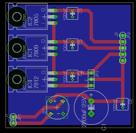
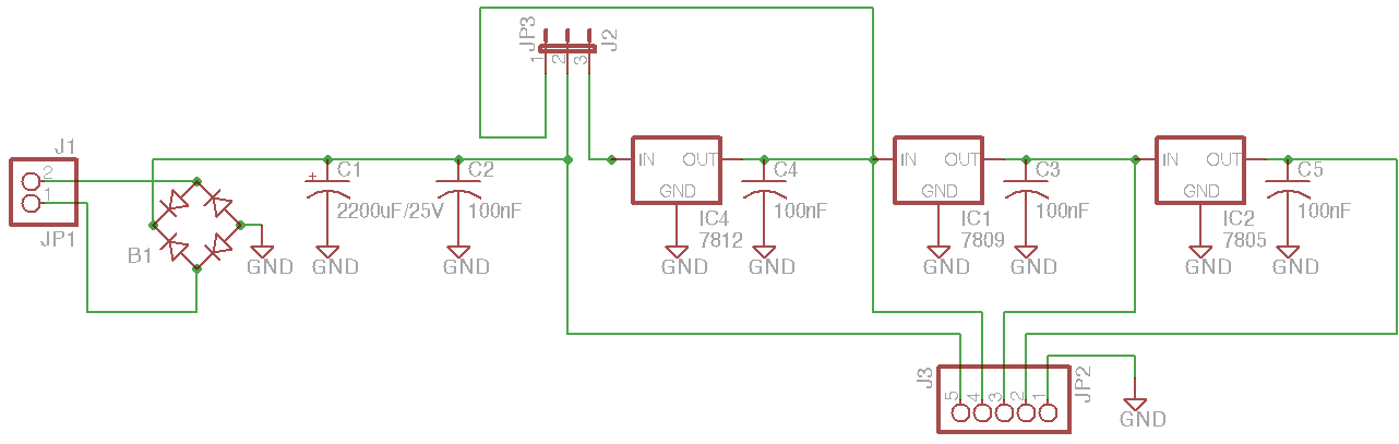
That's why I step down the voltage using multiple regulators. So it works like this: 15VAC -> ~14VDC -> 7812 -> 7809 -> 7805 I have a pin header after each voltage regulator such that you can pick from the ~14VDC, 12V, 9V, and 5V, depending on what you need (and if the devices you are powering have voltage regulators themselves). I'm thinking of also using jumpers so that you can select which voltage regulator to send the rectified voltage from. That way, if you only need 5V for your module, you can use a 9VAC wallwart and, thus, bypass the 7812 and 7809 voltage regulators (since they won't work with lower voltages anyway). That said, I'll have to check out the power board you are using as it looks like it does similar things and offers -12V. My design only works around +V so it won't work for projects needing bi-polar supplies (I haven't gotten quite that far yet in my own designs :). I suppose my design could be extended to offer both + and - voltages, but I think the first step is to get what I have working and to see if it still produces negligible degree of noise.
-
Me too! I know it can be done, but the question is if using voltage regulators is the way to go over, say, using transformers directly and generating the separate voltages using them. I don't know enough about this stuff to know what the impact will be. I do plan on building a prototype board hopefully this weekend and, if that works well, I'll spring for getting printed boards made. I've already made some modifications to the design I sent previously - I'll post an update once I'm happier with the configuration (I'm thinking of changing a few things to make it more configurable).
-
It probably is a fuse or something simple, but I haven't figured out how to open it without breaking things in horrible ways :) Basically, the +5VDC works and 9VAC appears to work, but cannot handle any load. If you place load on it, the voltage drops down to 1-2V. I've tried numerous tests and checks to see if components were in backwards, etc. All checks out, and since I already had a working C64 PSU board (that is now not working), seems to indicate it's the PSU. I'll continue to figure out a solution for the C64 PSU. I already have a printed board that seems like it will work great once I have a working C64 PSU. But, I think this might be a fun side-project to pursue since I won't get another PSU for another couple of weeks at minimum, and if I break another one, it'd be nice to have a backup plan :)
-
I spent all this time building a beautiful C64 PSU board only to kill my only good C64 PSU doing something stupid while testing it. So, after pondering over few ideas, I am now opting to make a non-C64 optimized PSU. I figure if I can get another C64 PSU great, but if not, I have something else to keep me busy :) My idea is to get a +12-16VAC wall-adapter and convert it to 12, 9 and 5VDC. Basically, I am taking the resulting voltage after the rectifier and smoothing capacitors, and then using a series of regulators to produce the other supplies (with a ceramic 100 uF cap after each step). Since you cannot drive a 7812 with a 12VAC supply, I'm planning on adding jumpers to bypass one or more of the voltage regulators so that one could use a smaller AC adapter. The idea is to offer up options that could be used both as a core MB-SID power supply, but also for other projects potentially. I also wanted to allow for mixing and matching 6581 and 6582/8580 SIDs. Anyways, I whipped up a quick schematic and board layout (attached) and was hoping to get more scrutiny from the community :) Specifically, I am curious as to if the ceramic caps after each voltage regular will help reduce noise that may come from the other regulators (since this was a concern of some). I am also wondering if I should use fuses and/or diodes in places to avoid killing my wall adapter and/or other components, much like I did with my C64 PSU. Thoughts would be appreciated :) powerboard.zip
-
I would also recommend loading up one of the example Drum Sequencer patches since they produce different sounds on the left and right channels (SIDs) so you can see if you are, indeed, hearing both SIDs.
-
Hey thanks Wilba! Glad to hear you've worked through some of these things :) I'm planning on getting some of your MB-6582 boards from Smash but haven't decided if I should keep trudging ahead with my own stuff (since it's fun :) - at least to finish up the small boards I've already been designing. My other curiosity is if I should try to find an analog power supply that is, say 9V and figure out how to step down from to 5V for CORE. I read some threads on the forum about some people doing that with a series of regulators (but that such things could be noisy) but, after killing my C64 PSU, I realized it's a pain in the ass to find a replacement one of these things over an analog transformer *shrug* Thanks again for the input!
-
So, since I have busted my current C64 power-supply, I've been trying to weigh my options (some including using something other than the C64 PSU). But, while thinking about it, I was wondering - with the C64 Optimized PSU, why is 14VDC being generated and then being regulated down toe 12/9 for each SID board? Would it not be more efficient to step down to 12 and 9 on the optimized PSU board and then simply remove the voltage regulators on the SID boards? I was curious why this was done over the above suggestion. Does it result in a lower signal to noise or something? In fact, if only newer 8580/6852A SIDs are being used, all that would need to be done when using the C64 PSU is to convert the 9VAC to 9VDC meaning no rectifiers are needed at all?
-
So my apologies as I didn't get around to photos yet, but I think I have ruled it down to the C64 PSU brick itself and here's why: If I hook up a standard switchable power brick, I end up with positive voltage at the end of the circuit. I can't remember the exact voltage but it was around 9VDC which is to be expected without adding in the 5VDC. This weekend I think I'm going to try using two wall adapters or otherwise find something that can generate 5VDC and try both adapters together to see if I end up with 5V and 14V using that. If so, it's gotta be the C64 PSU. Now I did try some isolated tests using my protoboard. If I remove everything but the bridge rectifier, I end up with 7-8VDC after the rectifier. If I add in the 2200uF cap, it drops down to 1-2V. So, it's possible my caps could be bad as well (going to order more of those just in case since you never know when they might come in handy anyway). I'll let you guys know once I work on things a bit more and can post some pictures of the tests (just ran out of time yesterday).
-
Sure, I can provide some photos when I get home from work later today. The part that is baffling though is why my old PSU board worked and now it doesn't. Unless a connection has gone bad somewhere, I don't see how that is possible. But hopefully pictures can help explain what I am doing wrong :)
-
...actually, how does one check the resistance? The pins aren't connected to each other before the rectifier? Err? I'm obviously missing something :)
-
I can indeed check the resistance. Bridge Rectifier looks good. The ~'s are hooked up to the 2 input pins for the AC. The odd part is that neither my known good PSU board nor my new printed board are producing the proper voltage. It seems like anytime I try to put load on the 9VAC, the voltage drops significantly (to between 1-2V). It's kinda strange actually. If I watch the voltage on the input pins while connected to either of my PSU boards, I can watch the voltage slowly climb, but it never gets all the way to 9V. I also tried hooking up 9VDC to the input pins (from a power brick). That works. So I'm confused :)
-
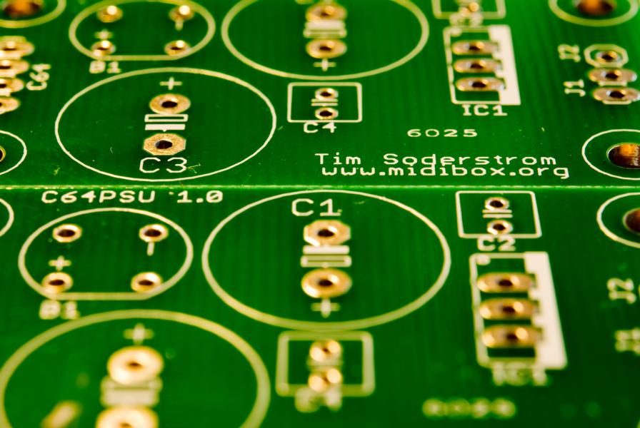
So the board came in yesterday woohoo! Looks great and is easily 1/8th the size of my protoboard (although it also is being used for the Bankstick board, which also came in). Trouble is, I think I may have busted the C64 PSU while testing the board. Basically, when I plug in the C64 PSU the voltage for the 9VAC is around 1.8VAC when connected to either my protoboard or my new board. If I disconnect the connector to the C64 PSU from either board and check the pins, I get 9VAC. The old board was working great before (I ended up with 14VDC after the voltage regulator) so I think I must've done something between steps A and B :) My guess is that it's the fuse in the C64 PSU itself? But though I would check to see if anyone had any thoughts?
-
Turns out the LCD was damaged. I had an extra one lying around so I soldered some pin headers to it, hooked it up, and everything is working! I can only imagine it was caused by me not hooking something up properly (backwards or without the resistor). That or static discharge is real :)
-
Actually, Stryd, to be specific, only 4 of the data-pins were connected to the LCD. I simply didn't have the pull-up resistor. At least not until yesterday :) So I think I was only half wrong. Same result could occur I suppose *shrug*. I kinda wish Smash would break out a 4-bit LCD optimized CORE but I guess that is something I may have to do myself at some point. ultra, I tried reflashing already but I didn't think about trying the ohm meter. That is one aspect I'm not too familiar with - what values would be considered bad? And I assume if it is bad, I just need to resolder the connections between the PIC and the LCD?
-
I have a feeling I may know the answer to this, but thought I would ask in case I missed something. My LCD was working fine but now seems to be flaking out. In particular, when I power on my MB-SID, it just displays bars across the top. It seems to flash briefly before it displays the bars again. Now it didn't work yesterday but today it seemed to work briefly. So I think it might be a bad solder joint, but I'm not sure how to test it. Just using my multimeter to trace the pins doesn't show any issues. This problem recently surfaced in the last few days. The LCD is running in 4-bit mode, and I'll admit I only recently added the pull-up resistor to the D3 pin. The problem surfaced before that, but has not gone away since adding it either. Thoughts?
-
Mine is supposedly still in the mail :) It's a good starter project for making your own PCBs and it's not terribly expensive. Here's a link to toe post on the topic: http://www.midibox.org/forum/index.php/topic,12009.0.html
-
*OH* ok so now that makes a ton of sense! Thanks to both you guys! I have no analog synths so I assume, then, that I don't really need a MidiBox CV :) But still want to eventually make a filter for my SID (once it's more functional anyway).
-
If you are using batchpcb.com, they also have a how-to for generating the proper files to suite their needs. Included are some additional scripts (for generating things like the silscreens) and such. It was pretty easy to do, but took a while to get everything perfect. So be ready for learning patience :)
-
Super elementary question, I know. I'm pretty sure I know what it does, but the description on ucapps.de, the forum, and even on x0xb0x (the Adafruit TB-303 clone kit) doesn't seem to help explain what the MidiBox CV, or more particularly 'CV' is for? I assume it is basically a way to do analog filtering? So the MidiBox CV, is basically then a generalized filter box? If so, I assume that it would be an alternative to adding a low-pass filter to, say, a MidiBox SID directly right? Can someone maybe clear this up? Or tell me where I can go for a clear "idiots guide to CV" description? :)
-
Not sure if it helps, but I had some initial issues with my banksticks. One was I had +5V connected to what was supposed to be ground on one of the banks. Whoops :) Another was my terrible wiring job (it was my first protoboard) which caused data corruption and, in fact, when I used teh SID 1.7 firmware, it would actually hang when formatting one of the chips. That said, you may want to double-check your wiring for the banks to make sure it is correct. I used this page religiously. Also, if you are making a multi-bankstick board, it might be worth building a printed board rather than trying to wire all that up on a protoboard. That's what I'm going to end up doing anyway.
-
I am using the RCA outs. The RF modulator indeed makes things look terrible and, in fact, it's more difficult for me to use that then to just use the RCA outs. Either way, thanks for confirming my suspicion! And thanks a ton for that link! I've been trying to find one like that to use as a reference for my MidiBox stuff. That's awesome!
-
Ok so this is totally off-topic (hence why I put it in the off-topic section :), but since many of us are hardware freaks, given our MidiBox projections, I figured someone might have run into this before. My NES works great - it probably needs the cartridge connector to be revamped/replaced, but it still plays ok - except for one problem. Wavy lines. I've tried quite a few TVs, some HD, some not, but all seems to display ugly, and somewhat large, wavy lines. The picture itself isn't distorted as much is the color simply disturbed. From what I know of arcade monitors, that sounds to me like bad caps. But I can't find any mention of NES cap-kits which makes me wonder if that's not the case? Anyone have this problem? I suppose I can try to re-rail this off-topic train if I said I wanted to use it for the MIDI NES cartridge :) But otherwise as there is no MidiBox-NES project, that's as far as I can go :) Tim