m00dawg
-
Posts
1,404 -
Joined
-
Last visited
-
Days Won
16
Content Type
Profiles
Forums
Blogs
Gallery
Everything posted by m00dawg
-
Multi-Tap Transformers Versus Voltage Regulators?
m00dawg replied to m00dawg's topic in Design Concepts
*smacks forehead* duh! I should've remember that! That said, I have updated the original schematic with the modifications. Will give it a go either today or sometime this weekend hopefully and let ya know what comes of it! -
I haven't tried doing that sort of thing through Cubase SE (you might be able to do this sort of thing in yours, so your mileage may vary). The way I do it is program my controller keyboard (Axiom 49 in this case). Cubase stores the NRPN information when I record the on the MIID track I have assigned to the MB-SID. This works well, and I assume you can modify these parameters from Cubase as well. This is, by the way, for MB-SID v2. MB-SID v1, which uses CC events should be easy to setup in Cubase. You can use this by adding an automation track for that CC event to the MIDI track (like what you would use to control volume and such). Hope that helps! I'd send you screenshots but I'm at work at the moment and don't have Cubase with me. On an aside, if you just want to setup the synth, you could use the new MidiBox SID editor. That thing is pretty hot!
-
Multi-Tap Transformers Versus Voltage Regulators?
m00dawg replied to m00dawg's topic in Design Concepts
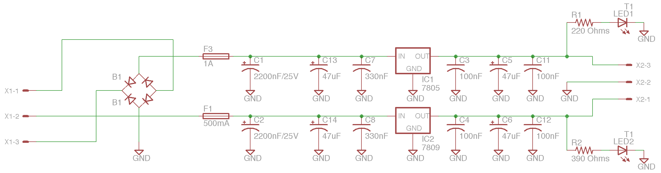
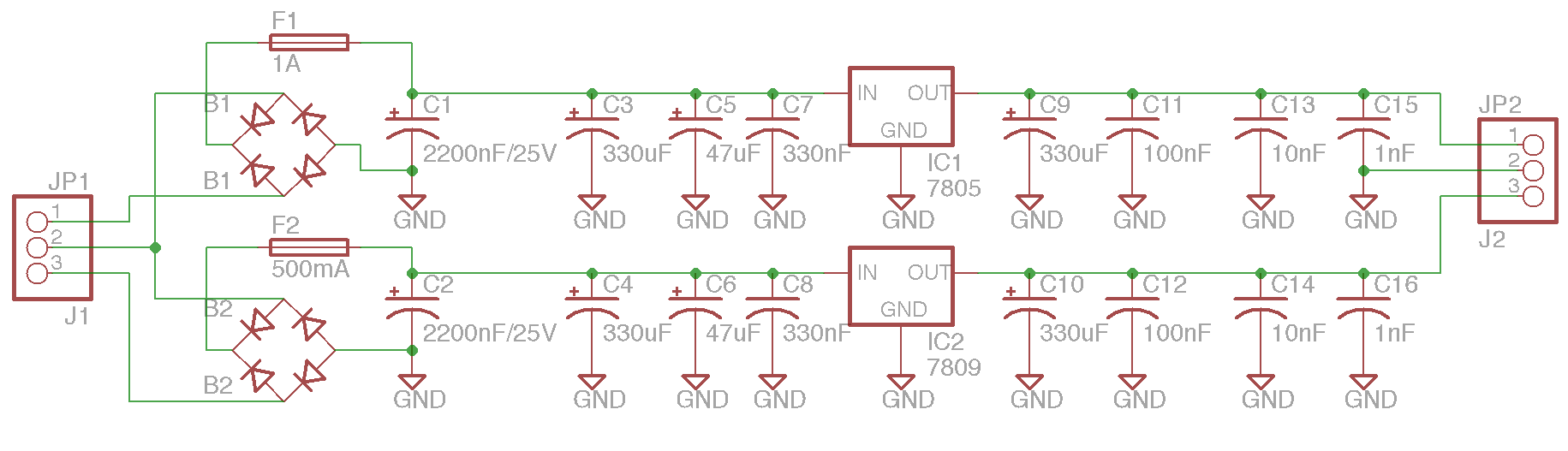
To dive in a bit more, after the regulator, why a 100nF followed by a 47uF? In other words, why not have the 47uF first and then the 100nF after? I assume it's to help better filter noise but I'm not exactly sure why? As for keeping everyone posted about my results, you can bet on that! I plan on making a nice, pretty, printed board of this thing when it's all said and done and would be more than happy to post my final schematic and board designs for all to use. I think there's a definite need for a clear alternative to the C64 PSU for those that can't get one or just want an alternative that's easier to work with, so hopefully someone can find all this work useful. -
Multi-Tap Transformers Versus Voltage Regulators?
m00dawg replied to m00dawg's topic in Design Concepts
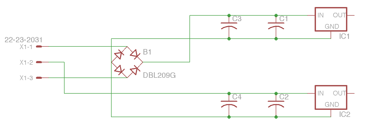
Wow that was very helpful and make sense! At least I think it does :) I've included a quick schematic of what I think you're saying. It's not complete - I just whipped it up to make sure I understood how I should connect the regulators. Looking at it makes sense, though, because both rectifiers are now grounded to the same thing and I'm still using the center-tap to pull half the voltage to feed to the 7805. On the note of the caps, I actually got rid of a few caps already in my current schematic (the one previous posted is a bit old by now), although I guess I could get rid of a few more. I figured more couldn't hurt and I wanted to make sure I was able to smooth out spikes and HF noise. But based upon what you say, it sounds like I just need: 2200uF -> 330uF -> 330nF -> Regulator -> 330nF -> 100nF Should I tweak that a bit for the 7805 since it's input is not being fully rectified (looks like it could be half-wave if I'm not mistaken)? By the way, thanks a ton for the great explanation. If you lived where I did, I'd totally go buy you a beer :) I hope, at least for now, my thanks, admiration, and gratitude are enough (and that extends to everyone who has helped!) -
Multi-Tap Transformers Versus Voltage Regulators?
m00dawg replied to m00dawg's topic in Design Concepts
Last night I finished the basic design (on a protoboard) and all seems to be...ok. The one problem I am having is that the +9V side keeps blowing a fuse and I don't know why. The only thing connected to it, other than the caps, regulator, etc., is a small blue LED (with a 390 Ohms resistor). When I power it on, the LED lights up, but then the fuse blows after 1-3 seconds. I'll admit, I got fed up with it and just bridged over where the fuse was (as it was a picofuse and was getting painful to keep re-soldering). When I did that, it worked without issue. I asked some people from my local hardware meetup group and they suggested it might be an issue with a component (cap, regulator) and I can determine that by lifting the grounds and putting them back in one-by-one. I don't have a resettable fuse to be able to do this outright, but it seems like a good idea. Any other thoughts though? The only thing I can think of is the fact that the GNDs aren't connected to each other (+5V has it's own GND and +9 it's own) - but they both connect to the same xformer so I don't think that should be a major issue at this point. Damn :) Oh well. The translucent blue case looks pretty nice that I have all this stuffed in at least :) -
*chuckle* Benefit of the doubt, maybe it was a gift :) It's a nice platform to make music on, to be fair (though wildly expensive to do so, both in software and hardware costs it seems).
-
Audacity is....ok as a wave editor. For Mac on the cheap, I'd go with Garage Band - at least for now. It does MIDI stuff and multi-track editing. Better than Audacity for producing music, I think. Win XP? Surely you jest!? I partially blame Win XP for my lack of completed songs from last year. Everytime I turn the damn thing on it annoying asks for some stupid Malicious Software Removal or Genuine Advantage bullshit update. Trouble is, to move to a Mac, it'll cost quite a bit of money - and I'd rather spend that on my MidiBox stuff :)
-
If you want to kick it Linux style, get Ubuntu Studio. It has some of these applications installed for you.
-
Hah, I didn't even notice we was tormenting it :P I'm not one to judge - I've been there. That said, Cubase Essential is all I really need and, with a little bit of saving up my extra bling, I can afford it. To each his own though. That's his conscience he has to live with :)
-
I use Cubase (SE 1.0, haven't upgraded to Essentials 4.0 yet but will do so at some point) with an Axiom 49. Apart form having trouble mapping multiple parts of the keyboard to different MIDI outputs / VSTs, it works like a champ. I mapped my controls on the Axiom itself, however, and not from Cubase. So, for instance, my Axiom is sending the appropriate CC / NRPN through Cubase to my MidiBox SID. I then save that keyboard config right on the keyboard itself. It's more cumbersome, perhaps, but does work quite well after all is said and done. Check your Axiom manual for how to set up stuff like that. It took a bit of playing around, particularly with the NRPN stuff, but it's all there in gory detail. Having said that, I do have to chime in as well that this post in this section is a bit off topic. But hey, now you know ;)
-
Well, I ended up having a bit more room after I rounded up the measurements (since BatchPCB rounds up to the nearest inch - I figure why not use the space). I added and re-arranged some caps around and was able to fit things in while using the "one after the other" approach. I'm still using bottom traces (sparingly) but have both a ground and isolation plane. I may look and try to see if I can put all the traces on one side. I'm going to build a prototype before I get the real board printed, so I have some additional time to test things out.
-
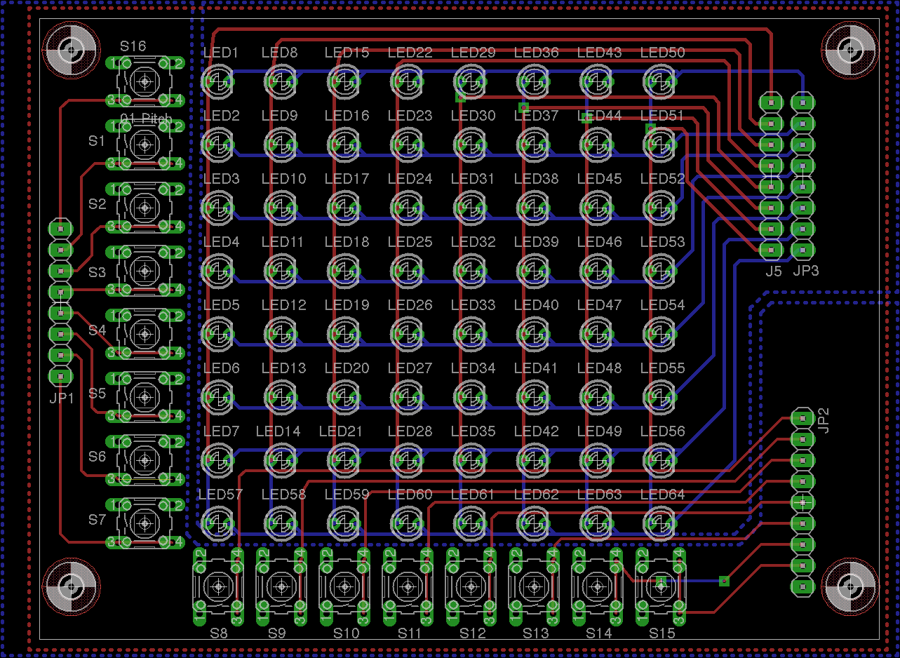
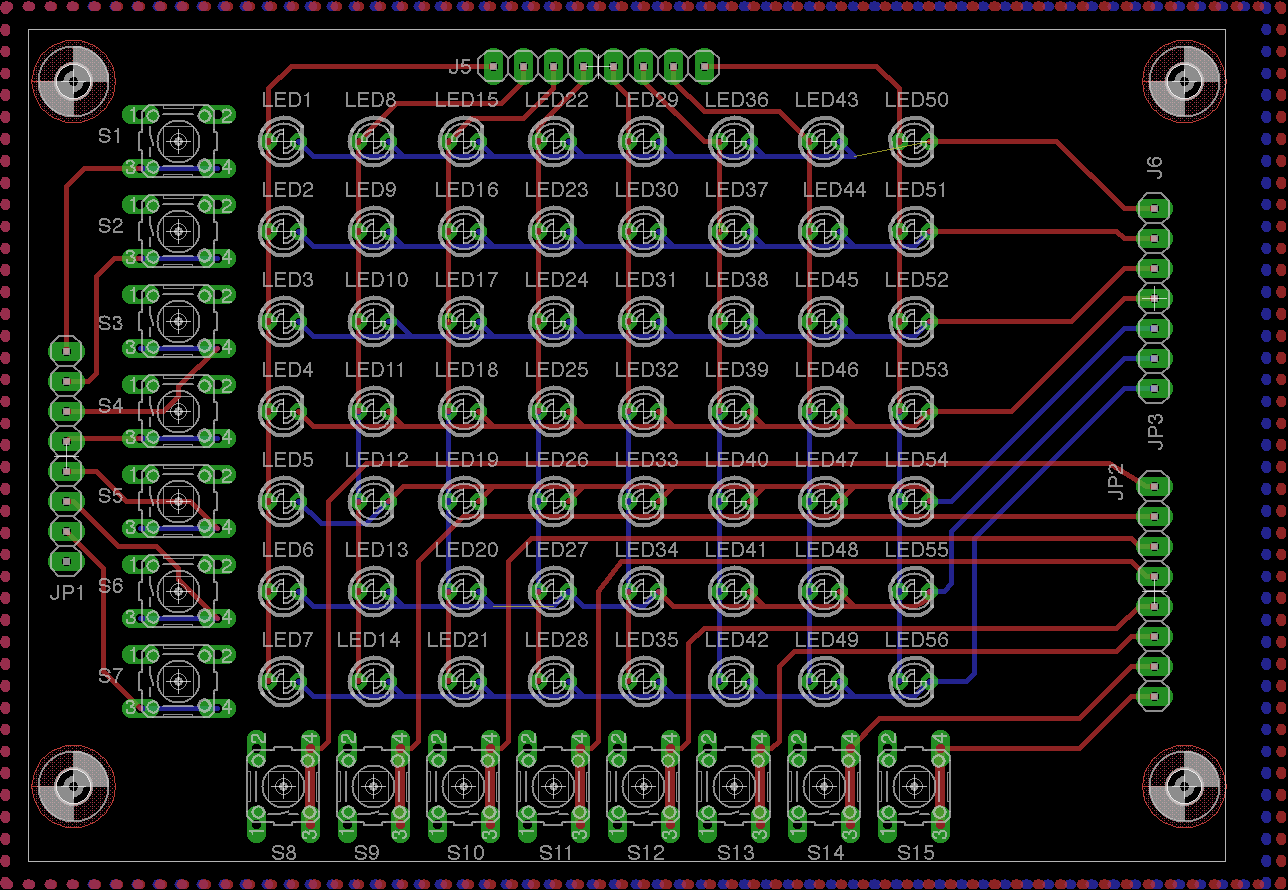
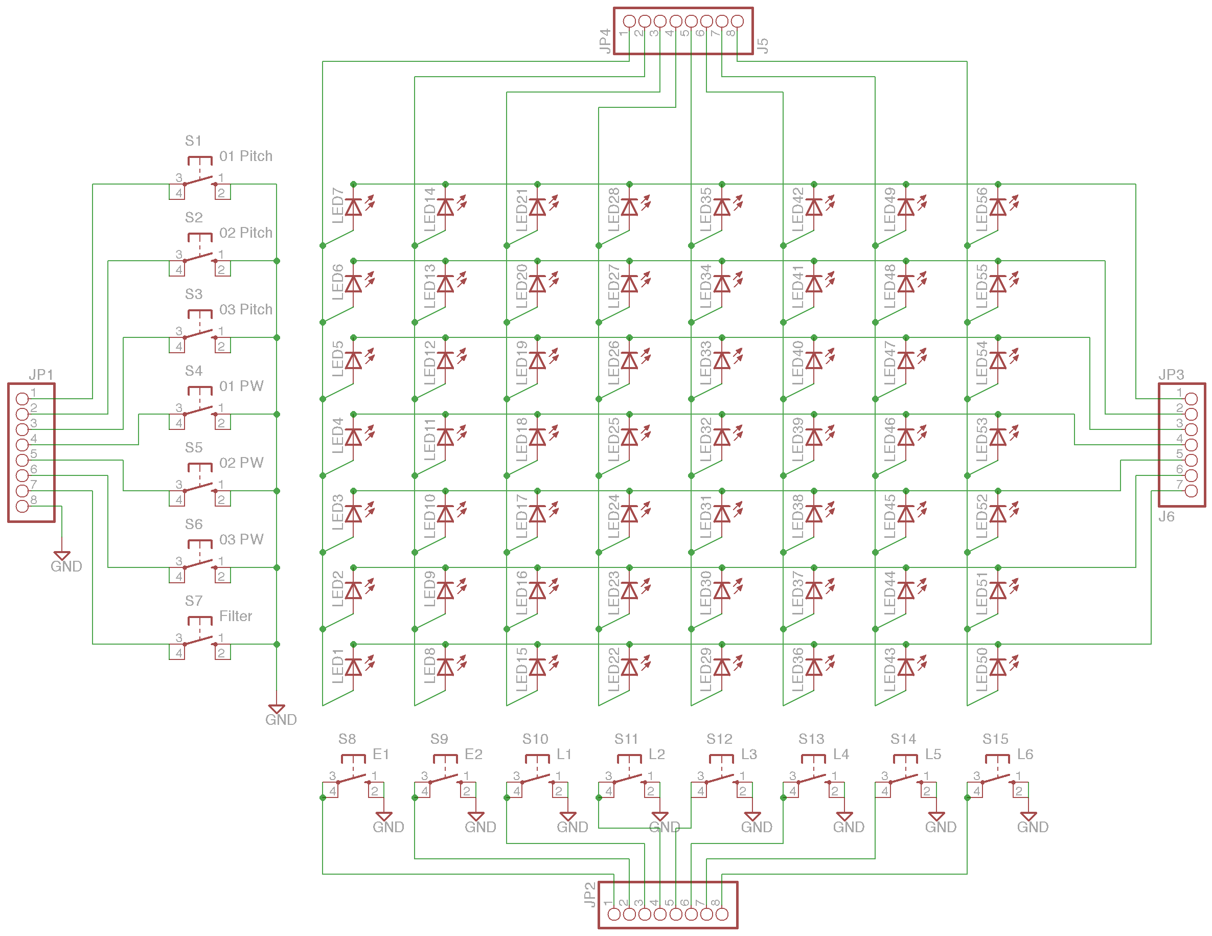
So the lack of the volume section was bothering me and I finally found some examples of how to fit the extra row on the C64 panel (thanks to Subatomic for sharing some very helpful information on this website). Here's the result. This one is even better than the first I think since it looks cleaner, though I had to end up using a few vias. I also have 3 planes (one to function as a GND for the buttons, and the other two just isolation planes). Not sure if that's a bit overboard but *shrug*.
-
Crap, good catch :) Fixed those up (can post an update if anyone wants it). As for the sr chips (shift registers I assume?) I thought about that, but I'm going to be using Wilba's MB-6582 board (and if not that, probably Smash's) and it seemed easier to work with those boards if I just used headers. If I was going uber custom, though, I could see that making a difference. Particularly when most of the C64 control surface has some nice gaps that could be used for this sort of thing. Something to think about though. For some reason, I really enjoy making boards in Eagle *shrug*. Meditation of sorts i guess, so you never know, maybe I'll throw that down. Heck, you could basically move much of the DIN/DOUT boards up into the control surface and just connect them all together. Hmm... My next goal, though, is to see if I can design or find a C64 front panel that will fit the full mod-matrix (with the volume section included).
-
I prefer having someone else (such as BatchPCB) print them. Costs more, yes, but I don't have to work with potentially dangerous chemicals, be subject to the shortcomings of my own fine craftsmanship skills, and it looks better :) BatchPCB doesn't charge more for multi-layer boards either so it tends to make things easy, albeit, at a cost ($30 for this board).
-
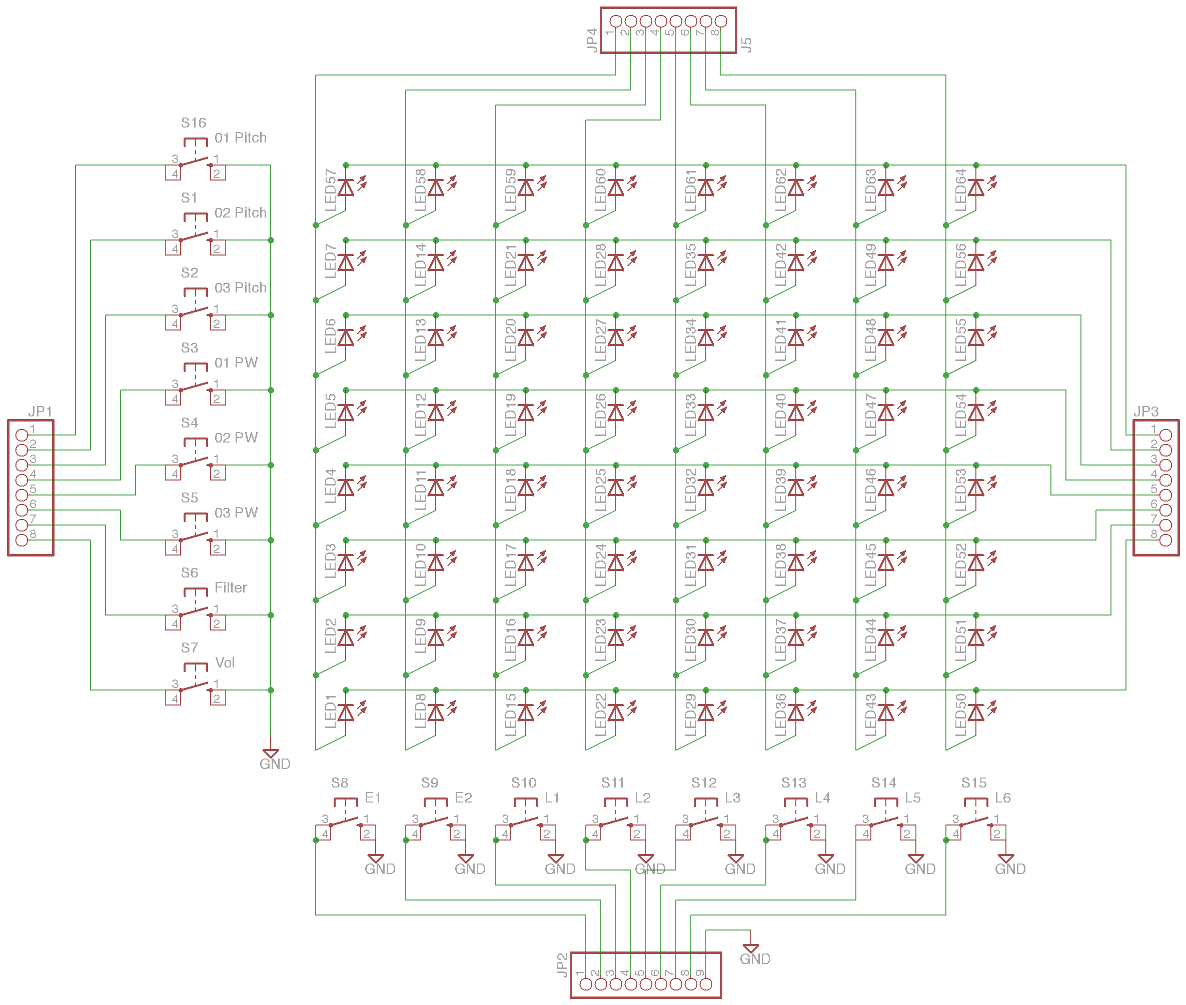
I didn't know if anyone could potentially use this, but I wasn't able to find one already after some searching and thought I would share. I made a reasonably quick schematic and board of the Mod Matrix in Eagle for the C64-based front-panel (available off ucapps). I took some careful measurements and it should line up rather nicely with the panel template. It doesn't include the volume section because the original template doesn't. I'm trying to see if there's enough room on my C64 case to add that (while hopefully not running into the limitations of the free version of Eagle). I figured this would be worlds easier than trying to make one out of a protoboard and it looks nicer too (since I plan on making my front panel translucent, aesthetics matter). I believe the switches SHOULD be the standard tactile switches also found in the examples. I picked the closest thing in Eagle I could find, but I'm not 100% sure (need to order more switches before I can determine this one). Anyways hopefully someone finds this useful, but if not, it was fun to make anyway :) modmatrix.zip modmatrix.zip
-
Multi-Tap Transformers Versus Voltage Regulators?
m00dawg replied to m00dawg's topic in Design Concepts
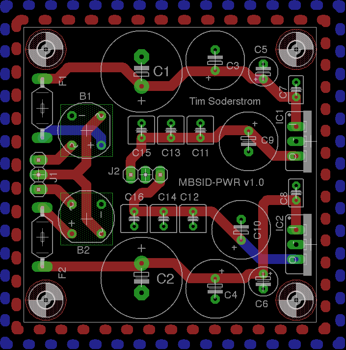
So I spent more time working on my design and thought I would share. I added a few extra caps for extra filtering. The values were sort of chosen using black magic and a bit of previous experience as well as some ideas mentioned earlier. I'll be honest, I also had extra room on the board (since I was going to use BatchPCB if I get this printed and they charge in 1 inch increments) so I figured "why not?" :) The only change I'm thinking about doing is adding an LED (the powerbrick style case I plan on getting is translucent). Comments welcome. I've got most of the parts selected so it's just a matter of ordering them and building a prototype. If that works, I'll likely get the board itself printed to make it look all nice. -
Actually, if I can throw a follow-up question out there. If I make my own DIN cable, are there any recommendations on the type of cable to use in between? I was thinking a 3-conductor 18AWG cable. Would a shielded cable be better (and should the shield be connected to GND or not?). Doing a bit of research, it seems like wiring it up to the DIN adapter should be easy enough - looks like I have the option to solder or crimp. Thoughts?
-
Yep, that was my plan. Specifically, I want to use PSU Option D. I haven't decided yet if I'm going to put mine in a PacTech case or use a C64 case. If I do the latter, it may not matter all that much since I might have to mount the power socket elsewhere. Where the socket used to go on the C64 would make sense, of course, that WAS a DIN socket anyway so I guess that would make sense. My only big concern with that is getting the cables. Thumbing through some catalogs, it looks like there are multi-conductor cables that would easily work - just not sure I'm confident enough terminating the cables with DIN plugs :)
-
I was thinking about doing that for my PSU. It won't be C64 compatible (it will output 9v and 5v DC), but means I can use a, more or less, standard plug (at least for MidiBox SID projects). I haven't looked, but I think that might make it easier to use with the MB6582 if I did that as well? The only concern I have is the cabling. Do they make premade 7-in DIN cables? Since it's pushing power, it seems like this might need to be heavier duty than, say, a MIDI cable. I figured since XLR cables seem pretty hefty and can be easily had, this might be a good option. You're right, though, they connections are noticeably more expensive.
-
Wow I didn't even think of using an XLR cable for power, let alone knew that they had more then 3-pin variants! That's pretty cool and may solve my own problems with getting power to my MB-SID. Clever idea!
-
Yeah that's sort of what I figured. I haven't seen circuits designed that way when I was looking around so I'm guessing there's a reason that is the case. Other than having to use both sides of the board, so far the only issue seems to be a longer run but I think that's marginal really. Thanks for your input and help, as always!
-
Multi-Tap Transformers Versus Voltage Regulators?
m00dawg replied to m00dawg's topic in Design Concepts
I dunno, a 90+db Signal-to-Noise using the C64 power brick is pretty good for a crappy old 8-bit synth :) Curious if that's the upper limit or if you can get any higher by going all audiophile on it's ass :) -
Both are good options, but before you go that far, I think the MB-SID itself might be enough. Have you seen the Bassline demos? One is on the main MB-SID site (http://ucapps.de/midibox_sid.html). The other is searchable on the forums (Bassline #4).
-
Well, the MB-SID v2 has a bassline mode, and you could use a MB-SEQ (http://ucapps.de/midibox_seq.html). Hope that helps!
-
Multi-Tap Transformers Versus Voltage Regulators?
m00dawg replied to m00dawg's topic in Design Concepts
:) At least you're honest :) That's sort of what I was thinking myself, though I slowly stepped mine down. Since the caps in parallel, the total capacitance will be greater either way. So I assume the object of the exercise is to find the best size and number of caps that produces the lowest noise while still providing enough capacitance for stable power. Metal-Oxide Varistors. A friend from work suggested using these before the primary side of the transformer to help protect against power surges. The keyword is help :) They aren't foolproof, but relatively inexpensive and would help protect those priceless SIDs. (Power-strips use MOVs if I'm not mistaken). I was planning on using a heatsink similar to that as well, though might be overkill for mine. My current power board actually uses a single 12VAC wallwart and uses a 7809 for the 9V and 7809 passed to a 7905 (probably unnecessary since both needs to be cooled). All that is under a big heatsink I took from a dead motherboard. This solution actually works and is surprisingly quiet but I was hoping to get better efficiency using a center tap transformer. Regards & Happy New Year Back At You! :)