m00dawg
-
Posts
1,404 -
Joined
-
Last visited
-
Days Won
16
Content Type
Profiles
Forums
Blogs
Gallery
Everything posted by m00dawg
-
Which C64 power supply has the most juice / current ?
m00dawg replied to Futureman's topic in MIDIbox SID
Uhh..., are you feeding the 5V regulator with 5V? I assume you removed your regulators if your PSU is supplying 5VDC? I'm in the "don't use a switched power supply" camp (I'm in the "I'm building my own damn PSU" camp :) ), but I was forced into using one when I was trying to figure out how to power my first CORE + SID. I just grabbed one that was rated above what I needed to feed my regulators (I think I used 12VDC) and it worked ok. I still wouldn't advise that but *shrug* if it works for you :) -
So I finally had a chance to replace the caps - 4 total. 1 was the 2200uF cap in the power section and the other 3 were on the main-board. When I pulled out the 2200uF cap, I was able to spot some additional electrolytics, but I can't get to them without figuring out how to take off the top shield of the power section (which is soldered to the mainboard). That said, after replacing the caps I did, there was a marked improvement. The wavy lines didn't truly go away until I cleaned the 72 pin connector and associated header on the mainboard (along with cleaning the cartridge itself). It is likely that simply cleaning it might've fixed all my problems :) I opted to try switching caps this time since the last time I cleaned it, the problem didn't seem to go away. Anyways, the Nintendo is working almost like new now, woot!
-
MBSID V2 (8xSID+8xMoog): The Rutger Edition
m00dawg replied to rutgerv's topic in MIDIbox of the Week
!!! That thing is so awesome, I'm sort of at a loss for words, except perhaps: Wow that's damned impressive! -
That would indeed be pretty hot. I assume it'd be like the Virus TI stuff (VST that talks directly to the synth). I noticed that, at least using the Min Control Surface, that the SID doesn't send out knob changes over MIDI. Can that be changed? If so, that would help alleviate this issue as well.
-
The way I record knobs in Cubase is to put them in separate MIDI tracks and group them together (usually under the main MIDI note track). So I'll have a track for, say, Cutoff, another track for Resonance, etc. Sometimes I group them if it's something I prefer to tweak simultaneously. These are standard MIDI tracks though, not automation tracks. You can edit each of these though in the MIDI List editor just as before. In fact, you can record them all to one-track, but you'll likely have to filter the events or, otherwise, it becomes a pretty confusing mess. In my case, I configure my Axiom to send the proper CC/NRPN commands, which Cubase simply records and then forwards to the SID. So, basically, I treat Cubase as stupid and don't let it do any interpretation of my knob events (some other MIDI sequencers can do some nice re-mapping - I've heard FruityLoops is especially good at this). Instead, I have a patch on my Axiom that is for the MB-SID, and one that is for my Virus. Not the best way of doing it, but it does work. This is one of the beefs I have with my version of Cubase since this also makes using the keyboard for multiple synths at the same time limiting. I'm really hoping Cubase Essentials 4 remedies this, though I'm open to suggestion on this issue too. Anyways I hope that helps :)
-
So while doing a buncha work on my MB-SID and related projects, I figured I might as well work on breathing new life into my NES. It works fine (the cart connection could probably be replaced, but it's not a huge problem) except that the video signal has waves and analog distortions on it. I'm using the RCA Video Out and have seen this both on new and old TVs. After some lengthy research (Google hasn't been very helpful), there were suggestions to replace some of the electrolytic caps. So, I busted out my NES and, sure enough, there's a 2200uF cap by the RF section. The problem is that the RF section is soldered to the mainboard in multiple places and has shielding sandwhiched in-between. I guess the FCC has crazy regulations regarding this sort of stuff, because it's next to impossible to get to the top-side of the RF board without desoldering some rather large solder points. Question I have is - has anyone tried that before? I am able to get to the underside of the board, which means I can replace the 2200uF (it's sticking out above the shielding that i can't remove which is how I know it's there), but I'm wondering if there might be other components to replace. Before I go desoldering the RF section, I thought I'd just check to see on the off-chance someone has done that before :) Either way, I'm going to go ahead and order new electrolytics for all the caps I find (there's a few small ones on the mainboard) and will let people know the results!
-
Multi-Tap Transformers Versus Voltage Regulators?
m00dawg replied to m00dawg's topic in Design Concepts
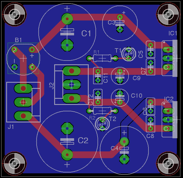
Oooh heat is a very good point. With no regulators in the synth, the only thing that right might eat up heat is going to be the SIDs it would seem. Well, that basically sells it for me! :) As for the pin-outs, I did that to make the board layout simpler since the top pins both go to the rectifier. I'm using Molex connectors there and was likely going to label the bottom pin CT or something along those lines to make it clear that it's not hooked up how one might initially think it would be. On the note of the Molex connectors, I picked those because they can push more than 1A. Seems like the standard SIL headers can't quite push that much from what I found (or, more specifically, the wires that fit into the crimp terminals for the female connectors). As for the GND, I didn't even know you could change the parameters of the GND plane! I played around with that and have attached an update. I was getting some stray airwires so I manually ran the GND traces and then applied the plane after that. Seems to have done the trick. As always, thanks for the input! -
Multi-Tap Transformers Versus Voltage Regulators?
m00dawg replied to m00dawg's topic in Design Concepts
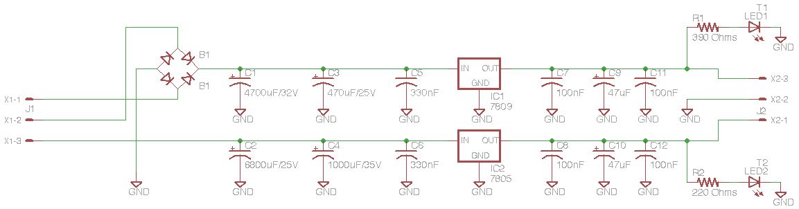
Ok so I'm still mulling over whether or not to do a C64-compatible implementation (I'm leaning on doing it the way we've been talking - the only thing that makes me hesitate is if I opt to go with a standard Pac-Tec case and backplate for my MB-6582), but thought I would share my current multi-tap design after we've talked about all this. I know. I went way overboard on the caps :) Not so much in number, but in the capacitance of the electrolytics. I figured more can't hurt, particularly since we've been talking about increasing the capacitance on the +5. So I basically tried to find common caps that fit on a 2 sq. in. board, while still having 2 electrolytics before the regulator. The caps are getting to be a bit tall at this point, so this solution might not make a whole lot of sense in a low profile design (though they aren't THAT tall). Feel free to use, comment on, suggest flame, etc. the design if you like :) Seems like, at this point, the design is more a result of our collective communal intelligence than just my own :) -
Newbie confused about the end of the MIDIbox DIY process
m00dawg replied to grnsky's topic in Design Concepts
Welcome to the forum! There is no better way to answer your question than to try it out :) There's also a walkthrough for the MB64 up on ucapps.de that should answer your other questions (yes, it should just work, but you have to map the knobs and buttons the way you want, both on the MB64 and in your application - the ucapps.de section on this should give you a good head-start). Have fun and good luck! -
Multi-Tap Transformers Versus Voltage Regulators?
m00dawg replied to m00dawg's topic in Design Concepts
So I'm kinda going back and forth between having my power brick generate both 9VDC and 5VDC and having it generate 9VAC and 5VDC. If I did the latter, it would be, theoretically a drop-in replacement for the C64 PSU. I didn't want to do this initially because my thought was that I could do more filtering in the PSU itself and also manage heat better this why. While playing around with this in the simulator, though, it got me to thinking. Why not use two rectifiers? Specifically, what if I only use the negative from one of the rectifiers (say, the one hooked up to the center-tap) and used that as my GND for everything after the rectifiers? I tried that in the simulator and everything seemed to work out fairly well. And if I built a C64-compatible PSU, I still need to provide a common GND pin right? Does this mess up anything with ground potentials and the stuff we were talking about earlier in this thread? -
Multi-Tap Transformers Versus Voltage Regulators?
m00dawg replied to m00dawg's topic in Design Concepts
If I understood you correctly, the thing I noticed in the sim was that you could starve one of the sides out. If I placed an simulated LED without a resistor, say, on the 9V side, eventually the 5V side wouldn't get any power. Doing that, though, meant that the 9V was drawing amps worth of current according to the sim. That said, it's basically assured that the +5V is going to draw more current than the +9V (at least with a full control surface, etc.). Both should be well under the 3A rating that my xformer has though and shouldn't starve out either half. This is getting a bit beyond my understanding though, to be fair. -
Multi-Tap Transformers Versus Voltage Regulators?
m00dawg replied to m00dawg's topic in Design Concepts
How is that different from what I had first though? Can you perhaps provide a screenshot of the circuit app? I think I may be missing something here, but when I hooked it up both sides were getting the same voltage (instead of one getting say 14V and the other 7V). I was thinking that, instead of using a full wave rectifier, I could use two half waves (so basically 3 diodes each top - two point forward and one points back. I'd need more capacitance, but, at least in the simulator, this seems to work. As for the caps, a 2200uF/25V cap is 13mm in diameter and 26mm high. A 4700uF/40V is 18mm in diameter and 35mm high. Not a huge jump I wouldn't think, but that would save space on the board. There's plenty of space but unless people want to bulk order the printed boards, I'd have to go with someone like BatchPCB, which chargers $2.50 per sq. in. So that can add up :) -
Multi-Tap Transformers Versus Voltage Regulators?
m00dawg replied to m00dawg's topic in Design Concepts
Would a diode make sense after the center-tap instead? I was playing with multiple rectifiers in the simulator yesterday and it ended up looking like it was doing crazy things, particularly when using a common ground. Of course I could be doing it wrong :) I'm going to finish making the DIN cable today and, if it is reasonably easy to do, can try powering my existing MB-SID (dubbed ShoeSID as it's in a shoebox :P) with it. Otherwise I may just wait until I'm far enough along on my MB-6852 since it would be easier to test that way I think. Given the results I saw in the simulator, I agree that more caps might be necessary. Are perhaps a few more with higher capacitance. Good thing about building this as a "power brick" (as opposed to inside the synth case) is that there's plenty of room to add caps so I don't see that as a huge issue. 4700uF seems to be plentiful just by browsing my electronics supplier. From what I saw, the +5V rail is the one that might need more capacitance right? I think the 9V should be fairly squared away with a 2200uF or so and the standard filtering caps we've been talking about? I suppose I could bit the bullet and opt for doing this with a single tap and regulation. I did some Googling of C64 PSU schematics and one of them just has a 7805 to drop it down. So, if that's indeed true, the C64 Optimized PSU design basically does just that. That said, another design I saw has it using a multi-tap xformer *shrug* http://www.commodore.ca/manuals/funet/cbm/schematics/computers/c64/c64-powersupply.gif http://www.devili.iki.fi/Computers/Commodore/C64/Service_Manual/Page_04.html If I opted for regulating, I guess I just need to find a beefier regulator and heatsink solution. I hate wasting heat though (hence why I wanted to try the center-tap design). -
Multi-Tap Transformers Versus Voltage Regulators?
m00dawg replied to m00dawg's topic in Design Concepts
Heheh fair enough. Here they are: http://www.moocowproductions.org/photodawg/album.php?albumID=27 -
Multi-Tap Transformers Versus Voltage Regulators?
m00dawg replied to m00dawg's topic in Design Concepts
Oh one more note...the caps I used aren't exactly what we've been discussing. I was running low on spare caps so I made a few substitutions. For the final design, I may use a slightly modified design as well (given what we discussed with the +5V side possibly needing a bit more capacitance). -
Multi-Tap Transformers Versus Voltage Regulators?
m00dawg replied to m00dawg's topic in Design Concepts
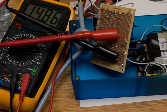
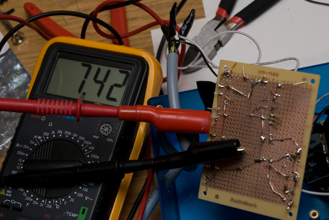
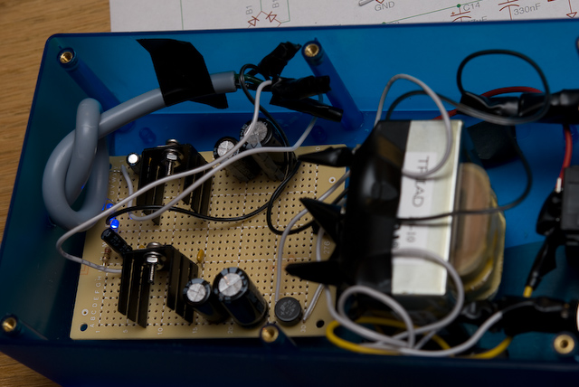
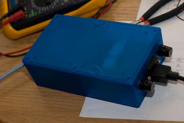
So I don't want to flood the forum with pictures of this thing, but here's 4. Two are what lylehaze wanted to see, namely the voltage before the regulators. The 3rd is a shot of basically everything after it has been installed and the 4th one is the box all closed up and ready to be used. I should point out that I haven't yet tested this with beyond the multimeter and 2 blue LEDs on the inside of the box. I need to finish making the cable to connect to my MB-SID. I've basically settled on a 7-pin DIN to resemble the C64 connector (with similar pin-outs is the plan, though obviously it won't work properly as a drop-in replacement though that wouldn't be hard to do). I ordered the wrong 7-pin panel mount DIN connector so, for now, the cable just is knotted inside the box. I'll let you know how those adventures go as soon as I get that far :) I hope to test it tomorrow but it took longer to build the circuit than I thought. Note that, if all goes well, I'll be making a printed board for this whole thing. As you can see from the pictures, I'm not so great at soldering on a prototyping board :) Plus a printed board looks way more awesome (and should take up less room, or at least let me match up the holes in whatever case I end up going with - either the blue on or, perhaps, one a bit smaller. And I can use some hardy Molex connectors for the power in and outs. One final question if I may. The power connector is a 3 prong and I'm not currently using that 3rd prong for anything. I know it's earth ground (and is there to protect oneself from stupid things) but I'm not sure how to connect it, even if at all. (by the way, if anyone wants to see more pics, though they aren't terribly interesting, I'm throwing them up on my website) -
Multi-Tap Transformers Versus Voltage Regulators?
m00dawg replied to m00dawg's topic in Design Concepts
It's about 15V on the 9V side (before the regulator) and 7V on the 5V side (also before the reg). Working on pictures right now, although I only have a multimeter. No oscope coolness or anything :) -
Multi-Tap Transformers Versus Voltage Regulators?
m00dawg replied to m00dawg's topic in Design Concepts
Ok I built the thing and it seems to be working like a champ! I haven't yet used it to power my current MidiBox yet, though, but there's no shorts, no blown fuses, both LEDs light up, and the output is +5 and +9VDC. I'll throw some pictures up soon, but for now, I need a break :) FYI, seppoman posted the link already two posts ago :) -
Multi-Tap Transformers Versus Voltage Regulators?
m00dawg replied to m00dawg's topic in Design Concepts
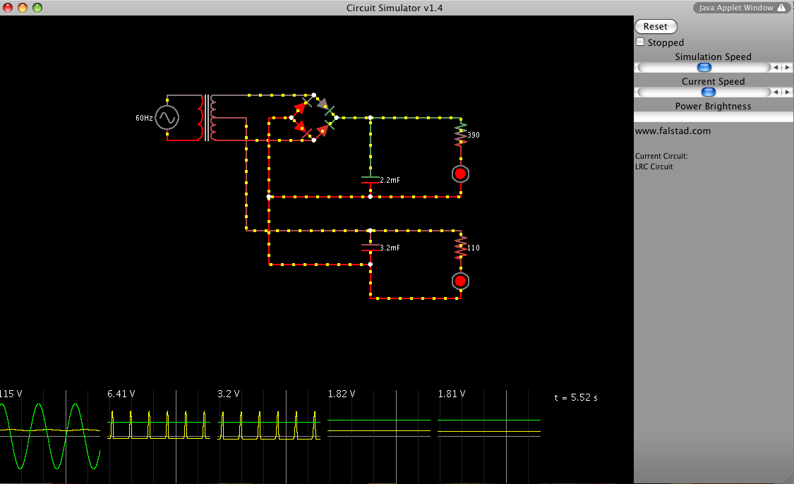
Seems like it works, though I did have to add more capacitance like you mentioned (the LED on the 6V side showed a dip in current otherwise). That's a pretty awesome little tool, by the way! The drop in current does seem to indicate that using multiple rectifiers might be a way to go as well. I really don't mind adding more capacitors though. The only issue I see is current draw. The 5V rail is going to be pushing more current than the 9V. Wilba's estimates put it at around 1A if memory serves. What's interesting is that I built my circuit that I was using previously and it sort of explains a bit of what was going on (and why I was probably blowing fuses). I'm going to keep playing around with this thing and then perhaps see about testing it. -
It's not quite the same thing but Renoise has a free version (you can't output to WAV) and it works well. I haven't used it for MIDI devices but for VSTs and such it works great. It's based (loosely) on Fast Tracker ][ from the DOS tracking era if you're familiar with that and the Demoscene. If you like it, the cost of the program itself is like $60 and it runs on both a Mac and PC.
-
One thing you might consider if you don't (yet) have a control keyboard (on an aside, you can build a MidiBox 64 to help with this :), have you considered using another sequencing program? I used to use Renoise and it's a fantastic app (and also quite cheap). It has some very nice automation at least for VST instruments and I think for MIDI as well. You might look into it if you don't plan on getting a control keyboard anytime soon as it may help. it's also a throwback to trackers if you prefer that style of interface. The only things I don't like about it are that I don't know how to record synths into a track for mastering (it may be able to do this - I haven't tried); and it can't function as a VST slave of sorts. That means it basically replaces Cubase for the most part. Still, it's a great program if you're looking for something different.
-
Ah there it is! Thanks TK! As for how to add CC events in Cubase, I couldn't figure out how to do it using an automation track (again my version is old) and, now that I think about it, I've always recording CC events from my synth / controller to the track and they show up on the main piano roll. That said, you can still manually add CC events. What you do is draw out a section of track (using the pencil thing). Right click on that and go to MIDI->Open List Editor. Then, on the window that pops up, select the pencil and also select Controller from Insert drop-down. Here you can basically add CC events by length. It's sort of like the piano roll in a way. It's a bit more tedious but should get what you want. Be sure to fill in Data 1 and Data 2 as appropriate to what you want to do (that might be the tedious part). As you have Cubase SX, you may be able to do this a better way.
-
If you're using 1.73 then you'll be using MIDI CC events. So when you add the automation track, there'll be the usual stuff (volume, pan, etc.). You just go to "More Options" or something along those lines and should be able to further configure that. I'll make an effort to send you screens when I get home though. I don't have the CC chart on hand for 1.73 so you may have to go tromp around ucapps.de to get that.
-
Multi-Tap Transformers Versus Voltage Regulators?
m00dawg replied to m00dawg's topic in Design Concepts
Not quite. It's a power-supply designed to replace the C64 power-supply in that it offers +5VDC and +9VDC. So I'm using the center-tap to half the voltage so that I'm jot jamming a ton of volts down the 7805's throat. I actually thought about making a supply that was 1:1 compatible (namely, it outputs 9VAC and 5VDC) so it could be used as a direct replacement. I opted not to go that route so that I could do some additional filtering. I am still going to try and make it almost pin-compatible so projects can be more easily modified to use it if need be. -
Multi-Tap Transformers Versus Voltage Regulators?
m00dawg replied to m00dawg's topic in Design Concepts
Doh! You're right! Oversights on my part. Fixed on my schematic. Will definitely let you know how it goes! Definitely looking forward to this weekend! I can't really do much work on my MB-6582 without this part squared away.