cosmosuave
-
Posts
259 -
Joined
-
Last visited
Content Type
Profiles
Forums
Blogs
Gallery
Everything posted by cosmosuave
-
Thanks will check these... J5 and resistor network orientations on the control PCB I assume...
-
Looking to clarify a statement here.... Initial setup for Wilba's Frontpanel Wilba's Frontpanel uses a special button/LED layout which is not compatible to the standard frontpanel. Accordingly, you won't be able to access the intended button functions as long as the standard assignments are active (e.g. no SD Card connected). In order to get the frontpanel working correctly, please copy the prepared configuration file hwcfg/wilba/MBSEQ_HW.V4 into the root directory of the SD Card by using the Filebrowser. I copied the file directly on to the SD card via Windows as in drag and drop and not with the Filebrowser could this be the issue I am having?
-
Yes the SD card shows connected...
-
This may soind like a dumb question but do I need to create a folder on tje SD card called Root?
-
Okay I copied MBSEQ_HW.V4 into note pad and placed it on the sd card yet the buttons are not behaving the way they should... I am obviously doing something wrong... If I push Track Group 1 the LCD shows Step Trg Layer 303...
-
I need help loading WIlbas front panel config file... I have it as a text and it shows on the mounted SD card with my SEQV4 but the buttons on the panel don't function as they should... The file shows in the MIOS file browser as a txt file... I think my issue is that it needs to be a hex file does MIOS allow me to convert this? I am so close to getting this working but am stumped and I have looked through the site to do this to no avail... When I try to DL Wilbas file from the wiki and various places I get file not found... Please someone chime in.... Thanks... Brian.
-
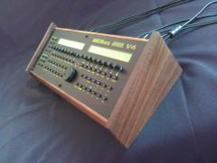 Nice build... That walnut?
 -
J4B it is then... Thank you...
-
More questions arise as I am completing my SEQV4 after looking at the documentation I am trying to figure out which jumper connection on MBHP_CORE_LPC17 does the MIDI Quad IIc connect to? I need to get the right connectors for this.. Is it J4B on the core or pins on J5B or a combination of both? Thanks... Brian
-
Currently I have the latest firmware V4.079 (searching for SD card) operating on my SEQV4 but have now added the SD card reader and went to DL MBSEQ_HW.V4.r1864 based on Wilba's front panel and get the follow mssg...Unable to open file: MBSEQ_HW.V4.r1864 Trying to remeber from stereoSID days I copied the file to notepad and gave it a .hex extension but MIOS is giving an error: No Blocks Found... Is there another location to get this file... Thanks...
-
J2 - It was clearly stated and for some reason my brain kept thinking J1... Thank you so much as this works now when I apply 5v to J2... Now I can move on...
-
Need some help on this.... I just got a new PS and I am supplying the core board with 5v... Upon start up I got the blinking led on the expresso board and the LCD's display but dimly when the contrast and brightness adjusted this is when I removed IC6 (7805) and jumpered pin1 to pin3 ... Also notes say to do the following.... When used as +5V input: for supplying the core from an external stabilized Power Supply Unit (PSU). The voltage regulator (IC3) doesn't need to be connected, also the rest of the voltage stabilization circuit between J1 and J2 (X1, C8, C9) can be left out. If the core module (and all connected modules to this branch) drains more than 100 mA, it's recommended to mount C8 directly to J2 (a small cable between the outer soldering pads of the left-out 7805 will do this) I removed X1 and now when I apply the 5v at J1 nothing powers up... Do I need to remove those other components as mentioned? I am hitting a roadblock with this and need to get past so I can focus on the AOUT and control surface... It is all good when powered via USB but I do not plan to use the sequencer with a computer... I keep soldering and desoldering parts and eventually I will have no pads to solder to... Appreciate some guidance... Thanks... bri
-
Thanks for the tip on the Meanwell... Just ordered one from Jameco and will install into my SEQV4...
-
Cool kinda the route I was going for... I measured mine and 10mm looks like it will do the trick...
-
Thanks guys your the best.... Have bookmarked that link...
-
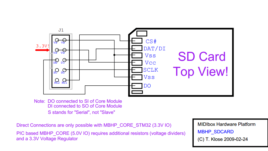
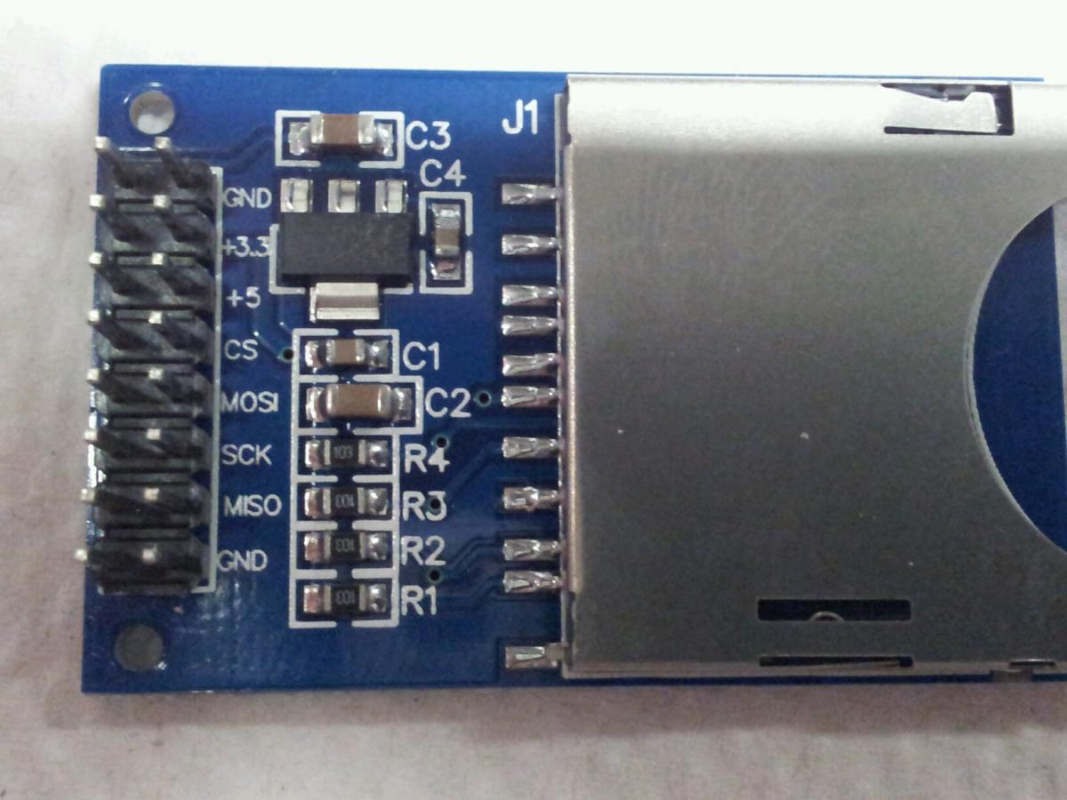
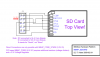
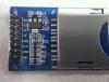
Hey I need some help translating the pin out from the SD card reader that I purchased to the pin out of Thorstens... Some of them match but then some have a different naming convention and i am unable to figure out by following the traces on the reader... BTW I got the card reader from Deal Extreme... This place has lots of stuff cheap and free delivery... I have bought lots of cables and a Arduino development kit for $50 from there... Thanks... bri.
-
This is the one I plan on building... http://www.musicfromouterspace.com/analogsynth_new/WALLWARTSUPPLY/WALLWARTSUPPLY.php
-
I rx'd my front panel for my SEQV4 and was wondering how high I should allow for the buttons should extend above the surface of the panel.. Should I have them just a bit above the surface so that I can drag my finger along to activate them in one swipe or have them extend full length which is about 4mm above the panel surface... What have you guys done? Thanks.. bri.
-
Gonna go with this diy power supply and add a LM7809 with a smoothing cap to the +12 v rail to supply 9v to the core (J1) and will use a 15VAC transformer instead of a wall wart...
-
Yes you are correct... The reason for the ATX supply is that I require +/- 12v for the AOUT module that I am installing... Will busy today researching DIY PS which may be my better option...
-
Removed IC6 and replaced it with a jumper but still getting the pulsing on and off with the LCDs... Should I remove all this as well "also the rest of the voltage stabilization circuit between J1 and J2 (X1, C8, C9) can be left out. " Just a note my voltage supply is 5v from a micro ATX PS and my meter is reading 5v from it... Think I toasted my PS as it arced out on it's case now I am not getting any voltage... Arrrrggghhh why did choose to make this non USB powered with the CV/gate board... I do not want to use 2 seperate power supplies for this... Surely someone here has done what I am trying to do... Sorry frustrated at the moment...
-
I will leave it for now... Those resistors are far easier to desolder than the pins...
-
Sockets fro the resistor network or the individual resistors? How do you socket individual resistors...
-
Hey guys thanks... I managed to get them all out which took a while due to such tight tolerances... My biggest fear was ripping traces off... The heat from the iron softened the plastic enough on the header that hey could be pulled out.. I need to observe these issues before assembly and not after... Still have to memory that one of the led's (31) I think is oriented opposite to the rest plus I manged to notice an IC installed the wrong way too... Julian is shipping my front panel off today...
-
Thanks and your right I do not need those modules... I find I get overwhelmed by the amount of info on this site...