cosmosuave
-
Posts
259 -
Joined
-
Last visited
Content Type
Profiles
Forums
Blogs
Gallery
Everything posted by cosmosuave
-
Bailed on the wood case and just got a piece of 1/8" aluminum bent in a channel... For the ends I will use wooden cheeks... Will busy drilling and dremmeling all the cut outs for connections....
-
I was thinking the same thing Julian I might even make some small 90 degree tabs with threaded holes to use as mounts... If I do this I may be able to salvage the case...
-
I am just gonna start from scratch again... Thanks for the replies... See in the pic where it has been circled this is where I am playing with a 3mm surface to mount to a case or I should scrap using those holes and use the 2 at each end....
-
Need to see a pic of that...
-
Let's see if I can represent this via ascii... Nothing that you have done Julian... Imagine looking down at the underside on the panel with the PCB control surface attached.... That space between these two is only a couple of millimeters which makes it hard to mount to the wood in my case.... If I had pics it would be easier to explain.. I think I am gonna have to go back to the drawing board and redesign my case... PCB EDGE------>| |<---------Front Panel outside edge
-
I have built a case for my SEQV4 out of 1/2" birch ply with threaded inserts to attach the control panel (Julian's ) and the issue is the holes don't line up and I do not want to elongate holes on the control panel... There is not much room for error as all you have to work with is about 3 to 4 mm of aluminum and wood as the edge of the pcb is only 3 or 4 mm from the edge of the aluminum control panel... I am ready to scrap the case after investing several hours of work into it.. Basically I want a case that will be rackmount and desktop those of you that have Julians control panel what did you use for a case? Is there a ponoko case out there for it... I am pretty much complete on my project except for the case... Thanks.. Brian
-
Thanks for the tip...
-
Reading this how do you get to the program change menu?
-
Jarly that technique sounds awesome... Dumb question but what does GP button mean?
-
Is that the feature similiar to Ableton's clip launch, where you can launch the pattern on a full measure 1/2 measure and so forth... If pattern is working for you I will try this route as well as it worked fine for me on the Machinedrum... Also you use a Machinedrum slaved to the SEQV4 is it fairly straight forward to have the seq change the patterns on the MD?
-
I am nearing completion on my SEQV4 and will be migrating from the Machinedrum sequencer which was my first hardware sequencer. I found it so easy to use and am looking to hear on how others use the SEQV4 live... With the MD I would use it in pattern mode using 8 patterns (A01 - A08) to construct a track and would like to know is this how others go about making their tracks or do you use the seq in SONG MODE? Now am I correct on this? If you are playing in SONG MODE you can morph into the next track without stopping the sequencer? The goal here is not stopping the sequencer to start a new track and to play continuously like a DJ... Thanks... Brian
-
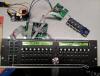
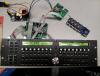
Closer to completion... AOUT_NG and QUAD_IIC module seem to work though this is prior to reconfiguring the firmware file to include those 2... I have the wood cut for my case and aluminum cut for the base and rear panel... All that is left to do is mount all the boards to the aluminum base drill out the rear panel for all connections and power and instal 1/8" cv/gate jacks... Question about cv/gate jacks... For all the grounds on the gate jacks should I tie them all together (bus) or run seperate? Should I do the same for the cv jacks? ***Note not using the DB25 connector for cv/gate...
-
Racking mine as well and I hear you on the space issues between the pcb and the edge of the face plate... I am constructing my case from 1/2" birch plywood... To fasten the face plate I will drill holes in the ply panels and epoxy female standoffs... For the rear I will rout a hole and inset an aluminum panel for all the midi and CV/gate connections and so forth... Once done this will go into my road case for Live PA and it looks like the DARK Time and Mbase01 will have to be removed to make space...
-
I have the one from Smash as well I guess it is just a straight connection... I just saw some documentation that showed extra parts req'd in all the documents maybe this was for roll your own.. Is your Quad IIc working? Keep us posted on the AOUT_NG... Another month and I should have mine done... Need to assemble the case and drill and cut the rear panel then stuff all the modules...
-
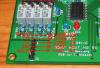
Did you have to add extra parts to make that module work? I saw documentation that shows it but not sure... The green led on my AOUT_NG works but i have yet to connect the bipolar supply to it yet...
-
Also remove the jumper for USB power if it is in place...
-
J2 will do it as I am running mine that way with a similar PS... Be aware of your polarity...
-
Found it and my led on the AOUT is working... Getting nesr the end.. Yeeha... Posted 16 February 2013 - 13:35 Quote 1 - GND (Vs) 2 - +5v (Vd) 3 - CS 4 - SI 5 - SC Just to be clear, the connections to J19 are: J1:1 -> J19:Vs J1:2 -> J19:Vd J1:3 -> J19:RC1 J1:4 -> J19:SO J1:5 -> J19:SC In addition, the AOUT_NG interface has to be selected in the CV Configuration menu (by default, the AOUT module is configured) Best Regards, Thorsten.
-
Which port does this connect to on the core? (J19)... If so the naming convention does not match as indicated in the pic...
-
Okay it has come back to me.... Below is the code you would change... # Following button functions are usually assigned to Fx # buttons, or to dedicated (labeled) buttons # In the standard frontpanel layout: # F1 is located at SR 2 Pin 1 # F2 is located at SR 2 Pin 2 # F3 is located at SR 2 Pin 3 # F4 is located at SR 2 Pin 4 # SR Pin BUTTON_UTILITY 2 1 BUTTON_STEP_VIEW 2 2 BUTTON_TRG_LAYER_SEL 2 3 BUTTON_TRACK_SEL 2 4 See the bold text above this is what you change... Then you paste in your Record, Length, statements... BUTTON_RECORD BUTTON_TRACK_LENGTH Now those two above are on different SR and Pin numbers but it should work... You cant ruin anything just keep your original config file and make a copy and do the changes to the copy then upload your changes... A bit of trial and error but you can figure it out that is how I did it...
-
Hey I am no expert but yes those Function keys can be rewritten fairly easily from those who know... My programming is rusty but if you look at the config file and find the section with Function key programming is just a matter of editing the target destination of the code... Just wait and someone will answer your post... It has been quiet on here for awhile... Just got mine up and running...
-
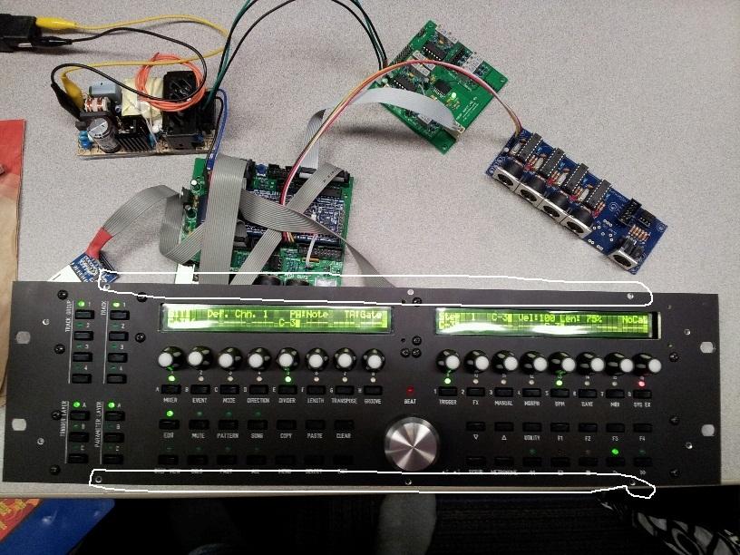
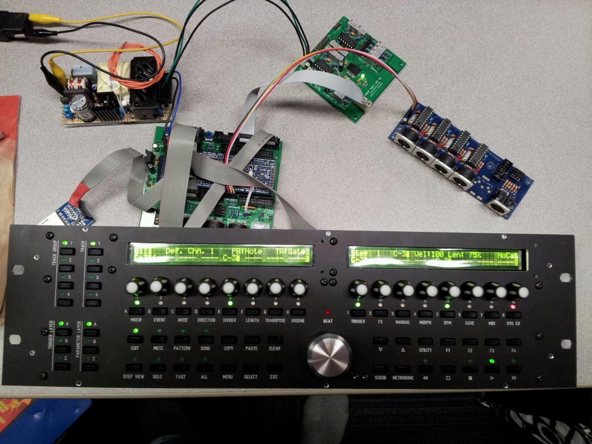
Finally got my MidiBOX SEQV4 running last night... Still need to make the case and config the analogue cv/gate board and I am done... Upon turning it on this thing is gonna be a blast to use... I wanted a Sequentix but could not pony up the cash and went this route... Will slave my MD to it and sequence my midi and analogue gear with all sorts of options... Thanks to those for your help as I ask some dumb questions when the answer is staring me in the face...
-
OMG it is working... Reloaded Wilba's file from another location on the UCAPPS site and it now works...
-
I have a spare LPCXpresso if you want... Not used...
-
Home now and tried a few things... 1. placed the config file on the SD card via windows.... 2. Able to download the config file from the SD card via MIOS when connected to the core... 3. Unable to create a directory sysex/: on SD card via MIOS getting mssg Failed to create directory... Seems that SD card works but the core is not recognizing Wilba's config file or there are issues with network resistors as mentioned I will check this later... Checked the resistor network and they are all orientated the correct way... Scratching my head on this...