Echopraxia
-
Posts
517 -
Joined
-
Last visited
-
Days Won
1
Content Type
Profiles
Forums
Blogs
Gallery
Everything posted by Echopraxia
-
Case grounding (need assistance)
Echopraxia replied to Echopraxia's topic in Testing/Troubleshooting
i tried swapping the v+ and negative and my box still powers up but acts the same way with the sparks. I am using the ultracore and I don't know if there is anything that I might be doing wrong with it. I don't have any of the IIC parts of it stuffed. I used the ultra core for the banksticks. Anything else I can try? I checked all my solder pads and they are not touching any of the case bottom. -
I just got an ensoniq CV expression pedal and was curious if I could use it with the MBSEQV4 using an analog input on the core32? And how can I set what parameter to use it with? Or maybe it would be better used on the MBFM?
-
Hi everybody, Just finished my MBFM but when I would make contact with the front panel and the bottom panel I would get little sparks. The whole case is metal. When I have the panels together My MBFM won't work at all. I read from an old thread about a metal front panel can become a antennae and you should ground it. I have always been testing the MBFM with the front plate away and when I put them together I was hearing a buzz sound which was the sparking. So my question is do I take an unused ground wire from one of the DIN or DOUT modules (mounted on bottom panel) and solder the wire to the front panel directly? Or should I be worried about something else. I have a metal power jack on the metal bottom case with a two prong 9v DC adapter going in.
-
YESSS!!!!! Success!!! Everything is working. You would think after finishing MBSEV4, DIN, DOUT, IIC, banksticks, core8, core32 and sammichSID with over 300 posts on the forum you would think I would know how to wire a switch correctly! :baby: Big thank you to Janis,taximan, nils, sparx and TK that last thought about the beep test and the button diagram made me realize that the switch operates differently than I thought. Once i paint this thing I post some pics.
-
that was it! All this time I have been connecting the wrong pins :poke: I have been connecting all of my other buttons with one pin on the top row (by the ground terminal) and the ground to one pin on the bottom row, and they have all worked this way. Oh well what ever. I'm finishing it right this moment and will hopefully be done with this thread.
-
I have these buttons : B3F-4100 page 6. I checked my connections with the beep test and was getting a beep without even pressing the button. I'm gonna try to swap either the din cable or the diodes to another pin on the buttons.
-
Active leg: typically on buttons there should be two active pins and two pins for ground right? i.e two active legs and two ground legs. I will have to give the multimeter beep test a shot. I'll check in about 6 hours from now. Thanks
-
I rewired it so the DIN J8 D1 is wired to one active leg of the button and the diode is connected to the other active leg of the button and still no results. Should I try DIN J8 D1 to active leg and diode to another leg besides the other active leg? i.e ground leg? I can smell the matrix but I just can't see it yet.
-
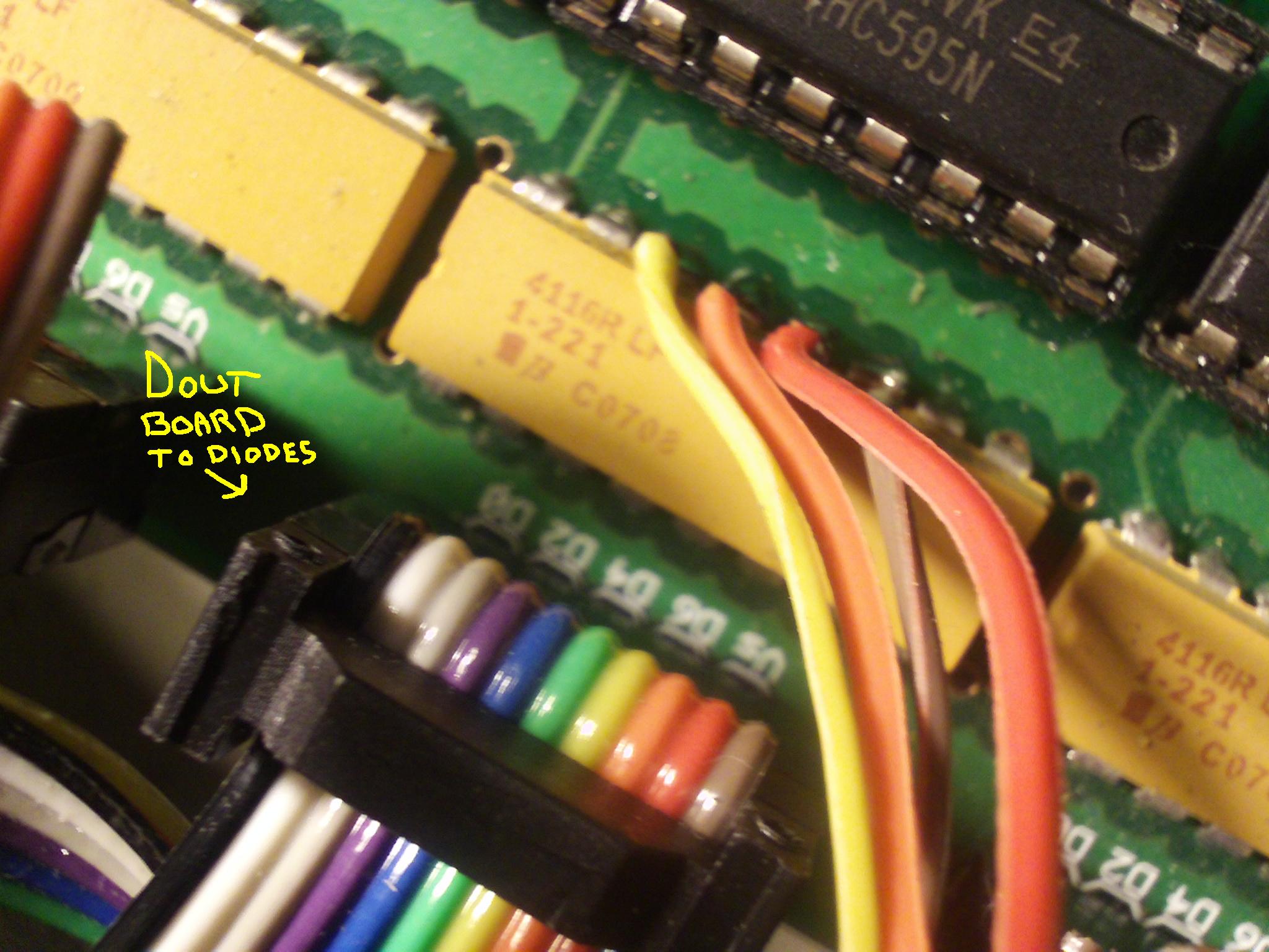
Now just to add to the last two messages :) I was just trying to see if the DIN cable is working. So I took a spare button and ran it to ground and placed the active pin on each of the diodes one at a time and when I would press the button I would get it to go to row 4 every time.And when I press this button I see row 3 light up faintly and go away real quickly while row 4 led is steady. So when I have a button connected to DIN J8 D1 and ground I get a response from my led matrix. so this should at least mena that both my DIN and DOUT boards are working properly now? I am using 1N4148 diodes just to clarify.
-
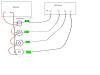
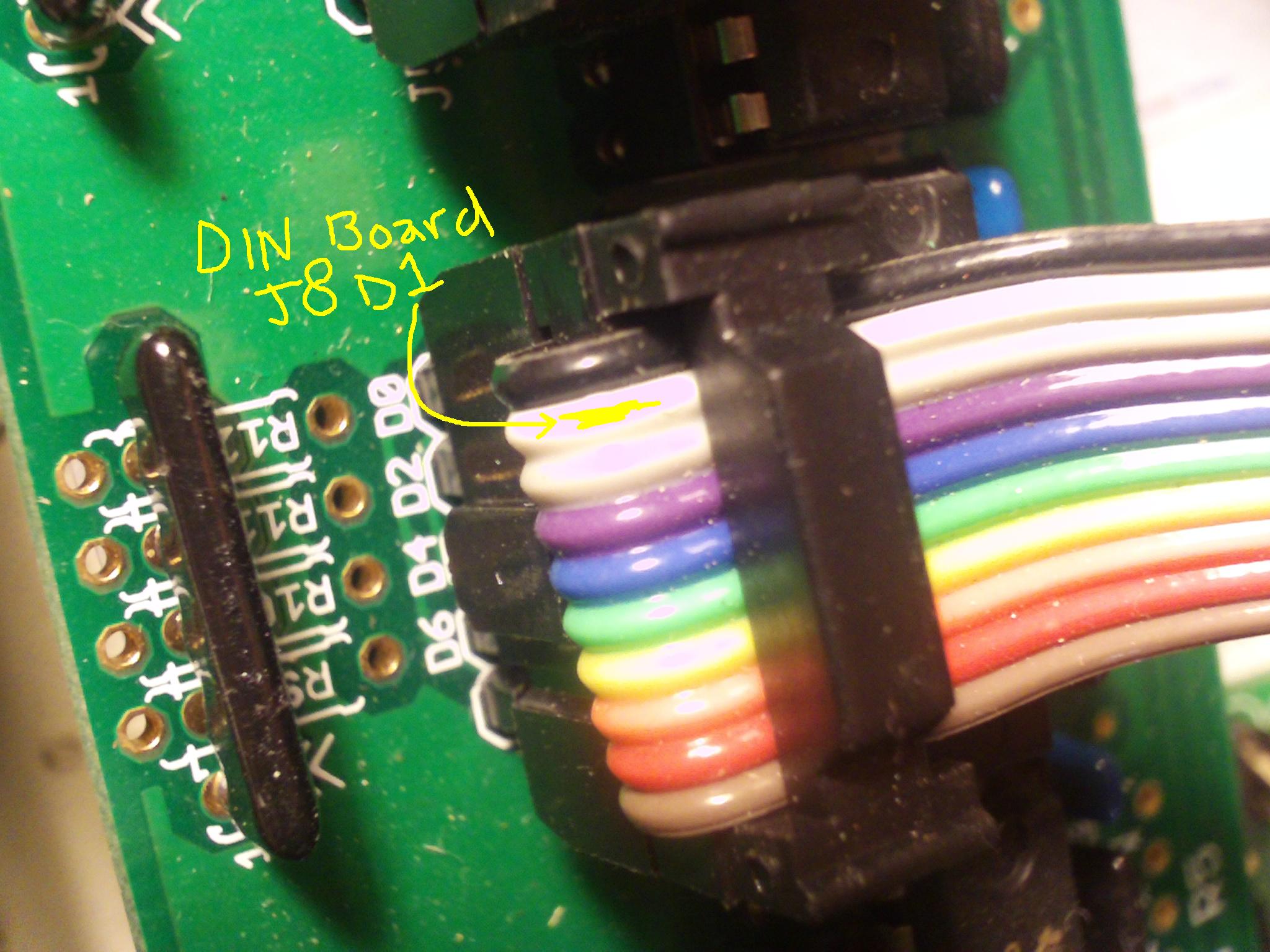
OK I have made SOME progress. I de-soldered all the DOUT cables going to the diodes and when I would strike them up against a diode or the DIN cable, my led matrix would change accordingly to which ever dout cable I hit a diode or Din cable with. I am getting the led matrix to change to the correct row by doing this (I finished wiring the led matrix and it works just fine). So what does this mean exactly? Am I getting a response from the DIN board that is connected to the buttons which are connected to the diodes which are being touched by the DOUT cables? My buttons still do nothing when I solder the dout cable to the diode. So what does this mean about the buttons and DIN? I tried a different DIN board which I had laying around for my old MBSEQ v3 with no luck. What is the easiest way to check the DIN J8 D1 voltage? Its almost like I have the wrong DIN cable connected. And just to confirm this DIN connection is | Shift Register | SR Number |Pin name |Pin Number |Hex Number | | third | 3 | D1 | 17 | 0x11 |
-
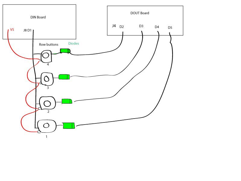
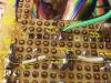
Sorry TK. Thanks for taking the time to help out. I have not yet finished wiring the leds yet. I was working on just getting the matrix buttons working. I had the column buttons working right away as they are straight forward. I am still having issues with the 4 row buttons. I was previously trying to figure out if I was wiring the diodes and row buttons correctly. I still have not been able to get the row buttons to work at all. At one point I had two of the four working but I cannot recall why. The behavior was strange and I think it was when I had the row buttons connected to a ground like any other button. I have them connected correctly (I believe) as one striped wire from DIN J8 D1 goes to all four row buttons then from each of the four row buttons to individual diodes (anode) then from the cathode side of the diodes to the respectable DOUT connections without ground wired to any of these aforementioned connections. You can see in the picture I have the DIN wire soldered right to the buttons and the diodes anodes soldered right with it. Maybe I need to wire the DINJ8 D1 to one leg of the button and the diode to the other leg instead of having them both on the same leg? I decided to start wiring the leds and I have row #1 working as it should. I feel confident that I can finish the led wiring but I still won't be able to check it until I get the row buttons working. I am gonna check tonight for maybe some bad IDC connections and triple check for solder problems beyond that I don't know if any one can help me at this point.
-
I'm pretty sure by now that I have the connections correct. I need to now find the fault in my soldering or idc connectors or something else.

-
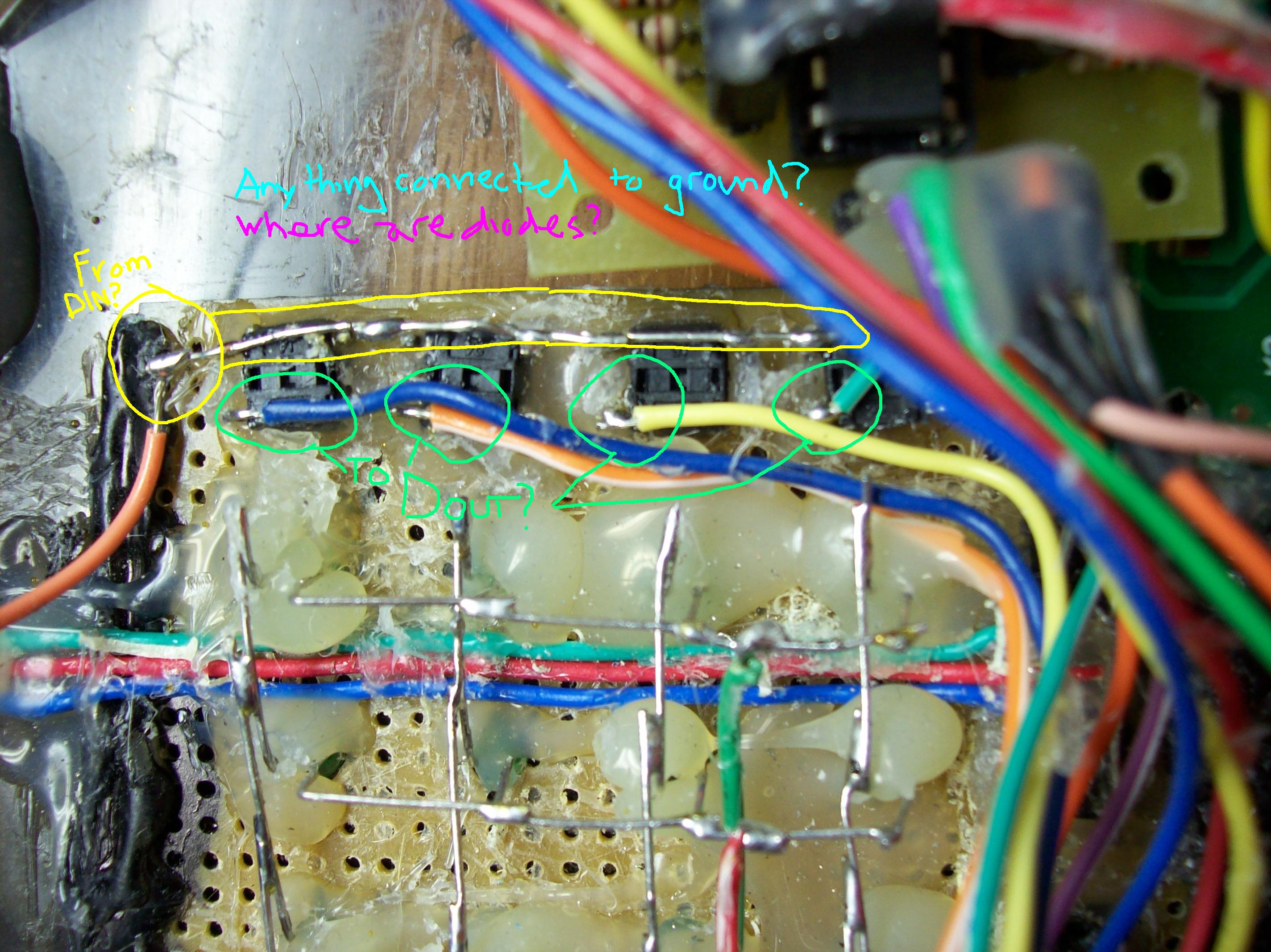
attached an image of taximans row buttons for reference.
-
Change modify DIN table on MBFM for button assignment
Echopraxia replied to Echopraxia's topic in MIDIbox FM
But the DIN SR/Pin only uses one button right? How do I get all 4 row buttons working? How do I assign Row 1 to DIN SR 5 Pin 0, Row 2 to DIN SR 5 Pin 1, Row 3 to DIN SR 5 Pin 2 and Row 4 to DIN SR 5 Pin 3? -
So I am looking at the DIO_M_ROW_ENTRY ;; --> 1*DIN/4*DOUT <-- pins of the 4 row select buttons ;; DIN SR/Pin, Row1 SR/Pin, Row2 SR/Pin, Row3 SR/Pin, Row4 SR/Pin DIO_M_ROW_ENTRY 3, 1, 2, 2, 2, 3, 2, 4, 2, 5 What do I need to change to define only the 4 pins on a new DIN SR. I would do DIN SR 5 PIN 0,1,2,3. Do I just delete The ;; --> 1*DIN/4*DOUT <-- Column and also delete the first entry which was labeled DIN SR/Pin like this? ;; --> DIN <-- pins of the 4 row select buttons ;; Row1 SR/Pin, Row2 SR/Pin, Row3 SR/Pin, Row4 SR/Pin DIO_M_ROW_ENTRY 5, 0, 5, 1, 5, 2, 5, 3 Or do I add it to the first Din column below DIO_M_COL_ENTRY ?
-
Change modify DIN table on MBFM for button assignment
Echopraxia replied to Echopraxia's topic in MIDIbox FM
So I am looking at the DIO_M_ROW_ENTRY ;; --> 1*DIN/4*DOUT <-- pins of the 4 row select buttons ;; DIN SR/Pin, Row1 SR/Pin, Row2 SR/Pin, Row3 SR/Pin, Row4 SR/Pin DIO_M_ROW_ENTRY 3, 1, 2, 2, 2, 3, 2, 4, 2, 5 What do I need to change to define only the 4 pins on a new DIN SR. I would do DIN SR 5 PIN 0,1,2,3. Do I just delete The ;; --> 1*DIN/4*DOUT <-- Column and also delete the first entry which was labeled DIN SR/Pin like this? ;; --> DIN <-- pins of the 4 row select buttons ;; Row1 SR/Pin, Row2 SR/Pin, Row3 SR/Pin, Row4 SR/Pin DIO_M_ROW_ENTRY 5, 0, 5, 1, 5, 2, 5, 3 Or do I add it to the first Din column below DIO_M_COL_ENTRY ? -
Hello, Can some one help me with changing the CS_MENU_DIN_TABLE on the MBFM for getting the row buttons on another DIN board. I can't get the interrupt service routine working and just want to use a second DIN board instead of going in to the DOUT for these buttons. Here is the table CS_MENU_DIN_TABLE ;; Function name SR# Pin# DIN_ENTRY CS_MENU_BUTTON_Dec, 1, 0 ; only valid if rotary encoder not assigned to these pins DIN_ENTRY CS_MENU_BUTTON_Inc, 1, 1 ; (see mios_tables.inc) and CS_MENU_USE_INCDEC_BUTTONS == 1 DIN_ENTRY CS_MENU_BUTTON_Esc, 1, 2 DIN_ENTRY CS_MENU_BUTTON_Sel1, 1, 3 DIN_ENTRY CS_MENU_BUTTON_Sel2, 1, 4 DIN_ENTRY CS_MENU_BUTTON_Sel3, 1, 5 DIN_ENTRY CS_MENU_BUTTON_Sel4, 1, 6 DIN_ENTRY CS_MENU_BUTTON_Sel5, 1, 7 DIN_ENTRY CS_MENU_BUTTON_Sel6, 2, 0 DIN_ENTRY CS_MENU_BUTTON_Sel7, 2, 1 DIN_ENTRY CS_MENU_BUTTON_Sel8, 2, 2 DIN_ENTRY CS_MENU_BUTTON_Cfg, 2, 3 DIN_ENTRY CS_MENU_BUTTON_InsOP1, 2, 4 DIN_ENTRY CS_MENU_BUTTON_InsOP2, 2, 5 DIN_ENTRY CS_MENU_BUTTON_InsOP3, 2, 6 DIN_ENTRY CS_MENU_BUTTON_InsOP4, 2, 7 DIN_ENTRY CS_MENU_BUTTON_InsOPSel, 3, 0 ;; the M_Row[1234] buttons are handled from an interrupt service routine! DIN_ENTRY_EOT ; ========================================================================== ; This short table lists the SR/pin numbers of the four ; Matrix Row Select Buttons. ; Since these buttons are multiplexed (4 DOUT pins -> 1 DIN pin) to save ; one DIN shift register, we have to define the DIN pin and 4 DOUT pins ; which are connected to these buttons (see also schematic) ; ========================================================================== DIO_M_COL_ENTRY MACRO sr0, pin0, sr1, pin1, sr2, pin2, sr3, pin3, sr4, pin4, sr5, pin5 db (pin0 + 8*(sr0-1)), (pin1 + 8*(sr1-1)), (pin2 + 8*(sr2-1)), (pin3 + 8*(sr3-1)), (pin4 + 8*(sr4-1)), (pin5 + 8*(sr5-1)) ENDM DIO_M_ROW_ENTRY MACRO sr_in, pin_in, sr0, pin0, sr1, pin1, sr2, pin2, sr3, pin3 db (pin_in + 8*(sr_in-1)), (pin0 + 8*(sr0-1)), (pin1 + 8*(sr1-1)), (pin2 + 8*(sr2-1)), (pin3 + 8*(sr3-1)) ENDM DIO_M_TABLE ;; --> DIN <-- pins of the 6 column select buttons ;; Col1 SR/Pin, Col2 SR/Pin, Col3 SR/Pin, Col4 SR/Pin, Col5 SR/Pin, Col6 SR/Pin DIO_M_COL_ENTRY 4, 2, 4, 3, 4, 4, 4, 5, 4, 6, 4, 7 ;; --> DOUT <-- pins of the 6 LED columns ;; Col1 SR/Pin, Col2 SR/Pin, Col3 SR/Pin, Col4 SR/Pin, Col5 SR/Pin, Col6 SR/Pin DIO_M_COL_ENTRY 2, 6, 2, 7, 3, 0, 3, 1, 3, 2, 3, 3 ;; --> 1*DIN/4*DOUT <-- pins of the 4 row select buttons ;; DIN SR/Pin, Row1 SR/Pin, Row2 SR/Pin, Row3 SR/Pin, Row4 SR/Pin DIO_M_ROW_ENTRY 3, 1, 2, 2, 2, 3, 2, 4, 2, 5 ; ========================================================================== ; The following table defines all available DOUT pins with the appr. ; register and bit which is assigned to the pin ; CS_MENU_LED_Update uses this table to update all LEDs ; ; The register name and bit number can be found on the left, ; the shift register and pin number on the right side. ; ; SR/pin numbers: ; SR = 1 for the first DOUT shift register ; SR = 2 for the second DOUT shift register ; ... ; SR = 16 for the last DOUT shift register ; ; Pin = 0 for the D7 output pin of the shift register ; Pin = 1 for the D6 output pin of the shift register ; ... ; Pin = 7 for the last output pin (D0) of the shift register ; ; Set the SR and pin number to 0 if a LED function should not be used ; ; The table must end with DOUT_ENTRY_EOT! ; ========================================================================== DOUT_ENTRY MACRO reg, bit, sr, pin dw reg, bit | ((pin + 8*(sr-1)) << 8) ENDM DOUT_ENTRY_EOT MACRO dw 0x0000, 0x0000 ENDM CS_MENU_DOUT_TABLE ;; Register and bit SR# Pin# Description DOUT_ENTRY CS_MENU_SELECTED_INS_FLAGS, 0, 1, 0 ; INS1 LED (Note: Pin #0 is the D7 output of first SR) DOUT_ENTRY CS_MENU_SELECTED_INS_FLAGS, 1, 1, 1 ; INS2 LED DOUT_ENTRY CS_MENU_SELECTED_INS_FLAGS, 2, 1, 2 ; INS3 LED DOUT_ENTRY CS_MENU_SELECTED_INS_FLAGS, 3, 1, 3 ; INS4 LED DOUT_ENTRY CS_MENU_SELECTED_OP_FLAGS, 0, 1, 4 ; OP1 LED DOUT_ENTRY CS_MENU_SELECTED_OP_FLAGS, 1, 1, 5 ; OP2 LED DOUT_ENTRY CS_MENU_SELECTED_OP_FLAGS, 2, 1, 6 ; OP3 LED DOUT_ENTRY CS_MENU_SELECTED_OP_FLAGS, 3, 1, 7 ; OP4 LED DOUT_ENTRY TMP1, 0, 2, 0 ; Instrument LED DOUT_ENTRY TMP1, 1, 2, 1 ; OP LED ;; NOTE: the pins of the MIDI Rx/Tx LEDs are assigned at main.asm DOUT_ENTRY_EOT
-
Hello, Can some one help me with changing the CS_MENU_DIN_TABLE for getting the row buttons on another DIN board. I can't get the interrupt service routine working and just want to use a second DIN board instead of going in to the DOUT for these buttons. Here is the table CS_MENU_DIN_TABLE ;; Function name SR# Pin# DIN_ENTRY CS_MENU_BUTTON_Dec, 1, 0 ; only valid if rotary encoder not assigned to these pins DIN_ENTRY CS_MENU_BUTTON_Inc, 1, 1 ; (see mios_tables.inc) and CS_MENU_USE_INCDEC_BUTTONS == 1 DIN_ENTRY CS_MENU_BUTTON_Esc, 1, 2 DIN_ENTRY CS_MENU_BUTTON_Sel1, 1, 3 DIN_ENTRY CS_MENU_BUTTON_Sel2, 1, 4 DIN_ENTRY CS_MENU_BUTTON_Sel3, 1, 5 DIN_ENTRY CS_MENU_BUTTON_Sel4, 1, 6 DIN_ENTRY CS_MENU_BUTTON_Sel5, 1, 7 DIN_ENTRY CS_MENU_BUTTON_Sel6, 2, 0 DIN_ENTRY CS_MENU_BUTTON_Sel7, 2, 1 DIN_ENTRY CS_MENU_BUTTON_Sel8, 2, 2 DIN_ENTRY CS_MENU_BUTTON_Cfg, 2, 3 DIN_ENTRY CS_MENU_BUTTON_InsOP1, 2, 4 DIN_ENTRY CS_MENU_BUTTON_InsOP2, 2, 5 DIN_ENTRY CS_MENU_BUTTON_InsOP3, 2, 6 DIN_ENTRY CS_MENU_BUTTON_InsOP4, 2, 7 DIN_ENTRY CS_MENU_BUTTON_InsOPSel, 3, 0 ;; the M_Row[1234] buttons are handled from an interrupt service routine! DIN_ENTRY_EOT ; ========================================================================== ; This short table lists the SR/pin numbers of the four ; Matrix Row Select Buttons. ; Since these buttons are multiplexed (4 DOUT pins -> 1 DIN pin) to save ; one DIN shift register, we have to define the DIN pin and 4 DOUT pins ; which are connected to these buttons (see also schematic) ; ========================================================================== DIO_M_COL_ENTRY MACRO sr0, pin0, sr1, pin1, sr2, pin2, sr3, pin3, sr4, pin4, sr5, pin5 db (pin0 + 8*(sr0-1)), (pin1 + 8*(sr1-1)), (pin2 + 8*(sr2-1)), (pin3 + 8*(sr3-1)), (pin4 + 8*(sr4-1)), (pin5 + 8*(sr5-1)) ENDM DIO_M_ROW_ENTRY MACRO sr_in, pin_in, sr0, pin0, sr1, pin1, sr2, pin2, sr3, pin3 db (pin_in + 8*(sr_in-1)), (pin0 + 8*(sr0-1)), (pin1 + 8*(sr1-1)), (pin2 + 8*(sr2-1)), (pin3 + 8*(sr3-1)) ENDM DIO_M_TABLE ;; --> DIN <-- pins of the 6 column select buttons ;; Col1 SR/Pin, Col2 SR/Pin, Col3 SR/Pin, Col4 SR/Pin, Col5 SR/Pin, Col6 SR/Pin DIO_M_COL_ENTRY 4, 2, 4, 3, 4, 4, 4, 5, 4, 6, 4, 7 ;; --> DOUT <-- pins of the 6 LED columns ;; Col1 SR/Pin, Col2 SR/Pin, Col3 SR/Pin, Col4 SR/Pin, Col5 SR/Pin, Col6 SR/Pin DIO_M_COL_ENTRY 2, 6, 2, 7, 3, 0, 3, 1, 3, 2, 3, 3 ;; --> 1*DIN/4*DOUT <-- pins of the 4 row select buttons ;; DIN SR/Pin, Row1 SR/Pin, Row2 SR/Pin, Row3 SR/Pin, Row4 SR/Pin DIO_M_ROW_ENTRY 3, 1, 2, 2, 2, 3, 2, 4, 2, 5 ; ========================================================================== ; The following table defines all available DOUT pins with the appr. ; register and bit which is assigned to the pin ; CS_MENU_LED_Update uses this table to update all LEDs ; ; The register name and bit number can be found on the left, ; the shift register and pin number on the right side. ; ; SR/pin numbers: ; SR = 1 for the first DOUT shift register ; SR = 2 for the second DOUT shift register ; ... ; SR = 16 for the last DOUT shift register ; ; Pin = 0 for the D7 output pin of the shift register ; Pin = 1 for the D6 output pin of the shift register ; ... ; Pin = 7 for the last output pin (D0) of the shift register ; ; Set the SR and pin number to 0 if a LED function should not be used ; ; The table must end with DOUT_ENTRY_EOT! ; ========================================================================== DOUT_ENTRY MACRO reg, bit, sr, pin dw reg, bit | ((pin + 8*(sr-1)) << 8) ENDM DOUT_ENTRY_EOT MACRO dw 0x0000, 0x0000 ENDM CS_MENU_DOUT_TABLE ;; Register and bit SR# Pin# Description DOUT_ENTRY CS_MENU_SELECTED_INS_FLAGS, 0, 1, 0 ; INS1 LED (Note: Pin #0 is the D7 output of first SR) DOUT_ENTRY CS_MENU_SELECTED_INS_FLAGS, 1, 1, 1 ; INS2 LED DOUT_ENTRY CS_MENU_SELECTED_INS_FLAGS, 2, 1, 2 ; INS3 LED DOUT_ENTRY CS_MENU_SELECTED_INS_FLAGS, 3, 1, 3 ; INS4 LED DOUT_ENTRY CS_MENU_SELECTED_OP_FLAGS, 0, 1, 4 ; OP1 LED DOUT_ENTRY CS_MENU_SELECTED_OP_FLAGS, 1, 1, 5 ; OP2 LED DOUT_ENTRY CS_MENU_SELECTED_OP_FLAGS, 2, 1, 6 ; OP3 LED DOUT_ENTRY CS_MENU_SELECTED_OP_FLAGS, 3, 1, 7 ; OP4 LED DOUT_ENTRY TMP1, 0, 2, 0 ; Instrument LED DOUT_ENTRY TMP1, 1, 2, 1 ; OP LED ;; NOTE: the pins of the MIDI Rx/Tx LEDs are assigned at main.asm DOUT_ENTRY_EOT
-
Hi every body, I have some concern with my DOUT4 board. I am trouble shooting it for my MBFM and on one shift register (J4) I am getting odd voltages on two pins (3.6v and 1.6v). When I pull the register out I checked the voltages and was getting 4.8v so I tried another shift register and got the same 3.6 and 1.6 voltages when inserted. I looked at the DOUT schematic and saw that only 2 pins are supposed to get 5v but on my board I am getting 4.8v in at least 4-6 places. Can any one tell me if this is normal? I am using a 9vDC 400ma to power a MBFM with full control surface. 4.8v is what I am getting across all active pins on all shift registers. Reason why I ask all of this is because I cannot get my MBFM matrix working which requires that 4 DIN buttons get connected to the DOUT board. Regards, echo
-
I started testing voltages on my DOUT modules and noticed I am getting 3.6v on one pin on my J4 shift register and another pin on J4 is only getting 1.6v. I took out the shift register and tested the socket and came up with 4.8v. I put another shift register in but same voltage drops occurred. I looked at the DOUT schematic but it only had 5v on a couple pins and I am getting more like 4-6 pins with 4.8v on each register. I had another DOUT board lying around but my bad luck, J4 was already striped of its resitor network back when I was gonna use a 3 digit led BPM for my v3 MBSEQ., so I can't use the other DOUT board to test. Can someone tell me what voltages I should get on the J4 register of the DOUT board? I seem to be getting different voltages on the different shift registers. When I have time I will upload the DOUT test app. And I will also edit the tables to use another register than J4 for the row buttons.
-
Still no luck :( My soldering is good and my idc connectors are good. I wired the row buttons like in the Janis' picture without any grounds (Vs) and get no response from any of the row buttons. Do I have to have a ground somewhere? I still have not yet wired the leds yet (if this matters) Are the diodes in the right direction? i am at the point where I wanna take an extra DIN module and reprogram the hex file to hook up 4 lousy buttons to it. :cry: And I also don't have any room in the case for it. :no:
-
Most excellent! Where do I sign up :thumbsup:
-
So no ground is correct? Thanks Janis!
-
I got breadboard in but not much help :( Here is a picture of what I thought to be correct. Isn't it this simple? I am going to check my soldering and idc connectors when I get a chance but if someone could at least tell me that this is a correct connection diagram I would be grateful. Please excuse the kindergarten picture. Do the leds cathodes have to be wired up at the DOUT J4 D2,3,4,5 (before the resistors) for these row buttons to work?