

Smithy
-
Posts
1,234 -
Joined
-
Last visited
-
Days Won
28
Content Type
Profiles
Forums
Blogs
Gallery
Posts posted by Smithy
-
-
Also check out the wooden case that Technobreath designed. It's a simple case based on Sauraen's metal enclosure that he repurposed.
I modified the 8 mounting holes so they would fit the wooden case.
I'll be using 8 threaded inserts for m3 screws that I bought on eBay.
You can find the pdf here:
http://wiki.midibox.org/doku.php?id=mbqg_tb_case
-
13 minutes ago, Phatline said:
ok - i wrote sauren.
if i get feedback from him - that he have a pcb - then i ask you @Smithy again - if you still have a alu-pcb then.
- mike.
Hey man. It's actually an FR4-Standard PCB. Non aluminium. But seems pretty robust anyway.
-
 2
2
-
-
23 hours ago, Phatline said:
hei, what do you payed on jlpcb for one set (devidet)?
is there a change to get a Sauren Frontpanel PCB anywhere?
- i am interested - but not sure that i get all i need to build this (the FM-PCBs are sold out - as example: https://midiboxshop.bigcartel.com/product/midibox-quad-genesis-board)Hey phatline, I paid a total of $184.26 for the 5 sets of the front panel and rear panel PCBs. I'm negotiating a partial refund for the lack of paper and the 2 boards with marks on them.
So that's $37 for 1x Front Panel and 1x Rear panel.
I *think* Sauraen may have some green MBQG_FP PCBs that have not been sold, a few years ago he had some left at least.
He is on travels at the moment so may not reply until he is home.
The Genesis module PCBs are sold out on Modular Addict, so I'm not sure if any more are available. The MIDIbox Shop is closed down and Modular Addict (USA) is the new shop for PCBs.
https://modularaddict.com/shop-by-brand/midibox-ucapps-deBest to check with Sauraen, another friend of mine is interested in buying a set of Sauraens PCBs and my panels also.
I also need to try and prioritize the people who already have MBQG_FP PCBs.
@Sauraen I could try and get some more people interested in buying PCBs by posting on relevant Synth DIY facebook groups and forums.
When I complete the build guide I think more people would be enticed to build their own.
Thanks for your time,
Smithy.
-
2 hours ago, ssp said:
Really pleased for you @Smithy they have come out really good. Shame about the scuffs, make sure you email them highlighting the damage and your payment for correct shipping, they may offer replacements. Looking forward to seeing the build!!!
Thanks dude! I filed a complaint with JLCPCB to get a refund due to absence of paper between the PCBs which I paid for and also a partial refund for the scuffed boards.
-
No idea who you sold the PCBs to @db0451 but I have front panels and rear panels I'm selling for the project here:
If you could PM the person you sold them to that would be a great help!
-
I have 4 Front Panels and 4 Rear Panels for sale.
Please see this post: -
Update especially for people who have ordered Sauraen's Front Panel PCBs.
TLDR: I have 4 Front Panels and 4 Rear Panels for MIDIbox Quad Genesis for sale.
Life got in the way of both me and @ssp, and we lost contact for a few years!
Thanks for your help dude, and if anyone would like acrylic panels laser cut you should contact him!
The good news is that I ended up converting the Front Panels in .fpd format to PCB format using Kicad with lots of editing and learning.
Here's how the Front Panels came out:.thumb.jpg.84a360a33d1de69162cc840dbc9cf859.jpg)
.thumb.jpg.2baf3677c7fb8c883c9a3d6475bfacfe.jpg)
I also designedRear Panels and this is how they turned out:.thumb.jpg.fd126a65ad1d649d7cb525eb43ba3026.jpg)
Please note that the mounting holes for the Front Panel are designed to fit the DIY Wooden Enclosure that @technobreath designed for me:http://www.midibox.org/dokuwiki/doku.php?id=mbqg_tb_case
You will need to use brass inserts that take 3mm bolts, drilled into the top of the case to be able to mount it.
I will update the Build Guide I'm making with details on how to do this:
The rear panel will require using a jigsaw or small saw to cut out the rectangle for the Rear Panel.I am really happy the way the precision of the Edge Cuts and how the silkscreen came out.
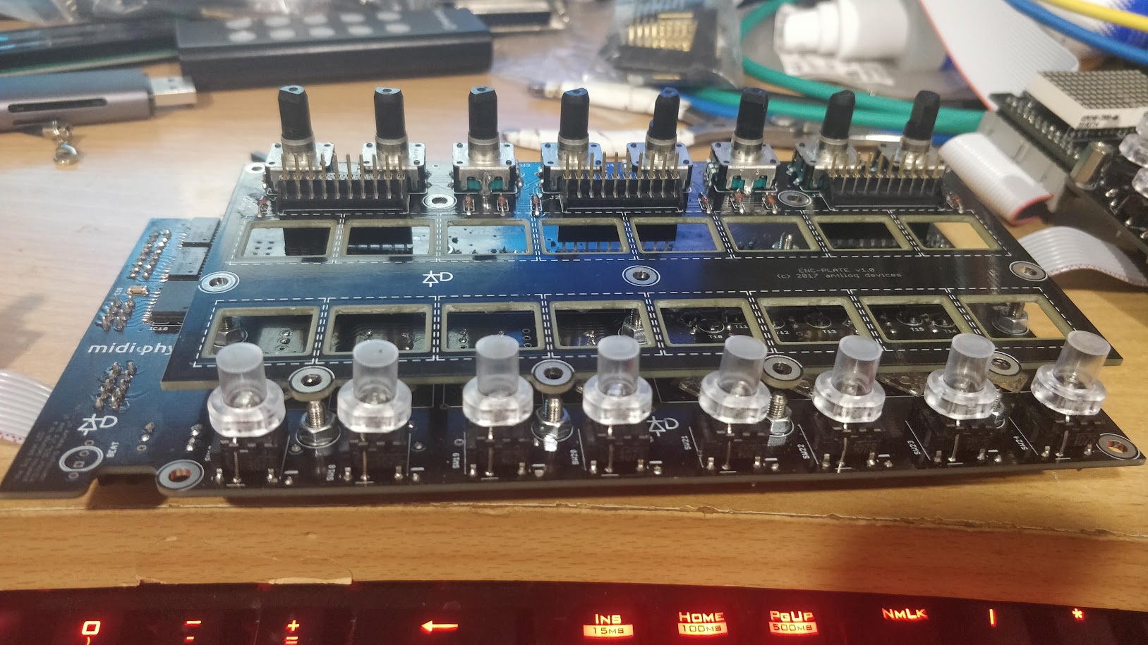
The Front Panel PCBs fit Saureans green pcb underneath perfectly as you can see in the first image embedded
Unfortunately JLCPCB did not put paper between the pcbs despite me paying for that option and 2 Front Panel PCBs had had minor scuffs:
.thumb.jpg.ebe2da5e955ec0f6d32d3ffe5f1be7b1.jpg)
.thumb.jpg.b6e4fda45651f3a8d5c25cfb2ffcf8f4.jpg)
Nothing a Sharpie Pen couldn't fix though.
If you are interested PM me and I can try and get a price for shipping it to your country.
Just posting to see if there's any interest now..thumb.jpg.b5a6d4dcb0f1cc19426c36e050b9a682.jpg)
.thumb.jpg.e3778063bcf08b3157fef633b34e8221.jpg)
.thumb.jpg.484616b1295505dac25afbf59280f723.jpg)
.thumb.jpg.64217fd561d31b72899a574cad8f0c37.jpg)
.thumb.jpg.e4381036115b69ba77c5b583b18370f9.jpg)
.thumb.jpg.8360efb7501356bf3985b5702ee9aefd.jpg)
.thumb.jpg.966b72a990b85fd72cf416d9eabdebbe.jpg)
-
29 minutes ago, TK. said:
Are you using this PSU? https://www.c64psu.com/c64psu/43-commodore-64-c64-psu-power-supply.html#/37-ac_cable-eu
I noticed that the 5V output sometimes only delivers ca. 4.5V, which is too low and can cause random glitches. Also display backlight becomes darker. Power-cycling the PSU normally helps to get it stable again.
Best Regards, Thorsten.
I am using a 12V 2A PSU that was used for an external harddrive and have Altitudes PSU mod installed on my MB-6582 with the fancy RECOM voltage regulators.
I've had the issue with the original C64 PSU and power brick also so there may be a short or grounding issue. I think I could feel a tingle before when touching the fan's metal grill.
I've procrastinated the repair in fear of making it worse but I will attempt to fix it someday!
Thanks for the help with the Arp, I will try it out!
I love how Insidious has the 4 clickable waveforms per step, as well as sync, ring mod etc..
And how it's much faster in general to recreate a SID tune.
Not sure if it's possible to copy that UI without losing some features in CTRLr.
If I have anymore ideas on a UI I will post them in the relevant CTRLr editor thread. Thanks Thorsten!
-
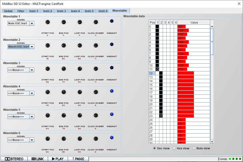
So the above is the result I get from MIDI track 1 (attached). Some unexpected high notes.
Central Park Loader.mid
Basically in wavetable 1, I'm copying straight from the video, Step 1 =0, Step 2 = +2 octaves, Step 3 = +1 Octave and repeated for the 12 steps.
In Wavetable 2, I want the Triangle Waveform to play on each of the 12 steps. So in hexidecimal it should be a value of 01 on each step?
I know that theres probably other ways of selecting the triangle wave but I'm trying to copy the video and understand how to put in the values.
It could also be an issue with my MB-6582 causing unexpected behavior, I need to resolder joints as I get some noise at times.
Any help would be appreciated, thanks. :) -

When I first started writing this post, the links opened fine from the User Manual on ucapps.de. Now I'm getting the page above. I can open the links from my post on the forum fine though?
I figured out 2 settings which were messing up the wavetables, Instrument 1 in Multi Engine was set to Poly instead of Mono.And the "Wavetable Only" was not enabled in Rutgers Editor.
Almost have the Central Park Arp sounding the same now except I get notes that are too high pitched.
I'll post the results in my next post below. -
The link to the 3 of these pages in the MIDIbox SID V2 User Manual Page are dead.
- MIDIbox SID V2 Parameter Chart
- MIDIbox SID V2 CC Implementation Chart
-
MIDIbox SID V2 SysEx Implementation
I'm trying out Rutghers Java Editor and can't figure out how to make an Arp with the Wavetables for the Last Ninja 2 Central Park Loader.
While the wavetables are more advanced on the MIDIbox SID V2 I think they are harder to program than Insidious. These are just my initial thoughts.
-
On 10/28/2023 at 8:26 PM, TK. said:
Thank you both - as you noticed, I'm solving some topics, but please don't expect too much in the next months, I just want to ensure that we are still able to play with our MIDIboxes (and of course enhance them) the next years

Need some time to think about this - The MBSIDV2 WT handler offers much more flexibility than the Reaktor based solution, and such a nice looking GUI won't be possible to implement with the given capabilities of Ctrlr. So, it's already clear: if I come up with a solution, it will be very pragmatic...

Best Regards, Thorsten.
I'll try playing with Rutgers editor in the coming weeks and will come up with some suggestions for the UI. Great to see you back!
-
On 11/24/2016 at 3:54 PM, ChinMuzik said:
^^^ so this doesn't edit wavetables?
So the only way to program wavetable sequences is through the MIOS menu?
Is there any non-Hex windows based application that can edit sequences? I hate to say it..but Mode Machines had a really nice way to do it.
Rutgers Java Editor has support for editing wavetable sequences, you need to have your MIDIbox SID connected via midi, both the output and input of your MIDI interface.
You can download his editor here:
http://www.ucapps.de/midibox_sid/v2_editor/MBSIDV2_Editor_v0_5.zipBut yeah, it would be great to have a complete editor on Ctrlr.
-
Amazing to see you active again Thorsten!
Have you any plans or even the time to finish the Wavetable Editor for the Ctrlr panel?I would love to recreate the wavetables from classic c64 SID tunes.
Fabio Marinelli is doing some great recreations using the Insidious VST on his youtube channel, and actively shares MIDI and project files for Cubase and FLStudio on his discord.
If a clean UI could be made to simplify the process of sequencing of wavetables (something like the one in Indsidious) I would really be interested, i think Hawkeye is going through of a phase of exploring the classic wavetable sounds at the moment also!
As always theres the older and free Reaktor Plugin for Insidious also:
https://www.native-instruments.com/en/reaktor-community/reaktor-user-library/entry/show/8572/
Great to hear from you again, and hope all is well in Bavaria! -
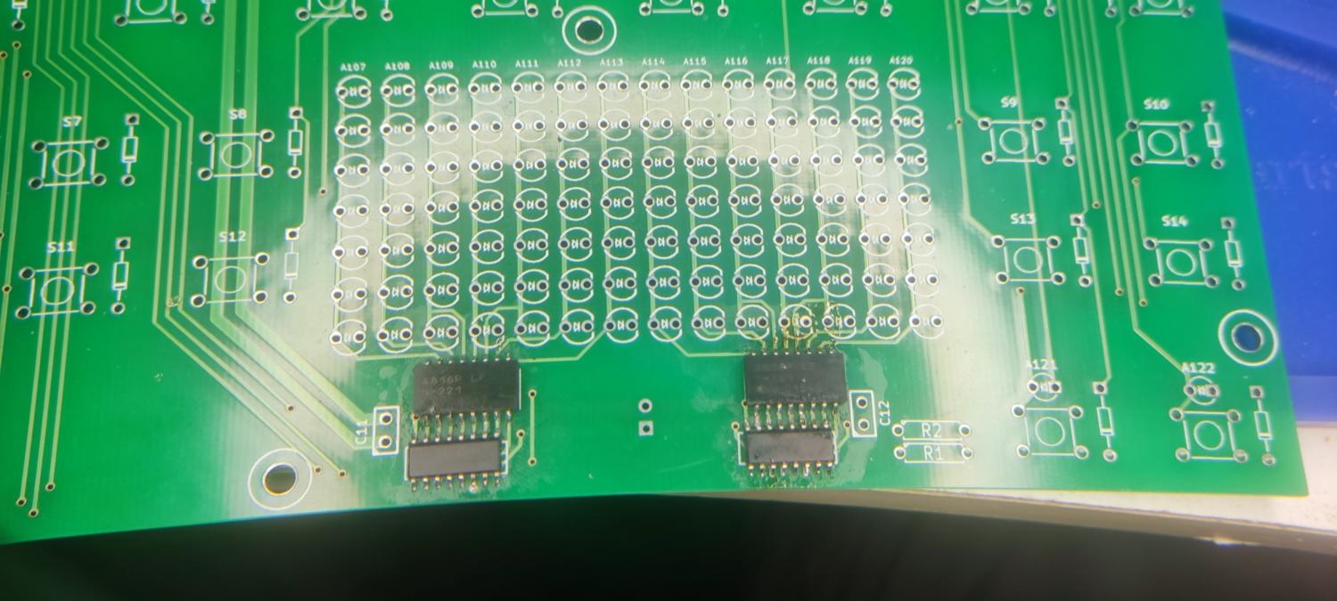
Soldering the Front Panel PCB
From the Wiki:
"Begin by soldering all the SMD shift registers and resistor packs. The pads aren't very big (if I had known, I would have made them bigger…), and I had a lot of issues with bad connections because a leg which looked soldered wasn't actually attached. If you have access to solder paste and a heat gun, use that. If not, apply solder to two corner pads on the board, place the chip on and melt those two legs into the solder to connect them. Adjust the position so that all the pins line up correctly. Then solder the rest of the legs, making sure to press down firmly with the iron on each leg just before applying the solder, in hopes that the leg will conduct heat to the copper and then when you apply the solder it will flow across the two."
This is the most difficult part of the build and Sauraen was not messing around when warning about the small size of the pads.
I tried drag soldering the SMT IC's and even though I used liquid flux most of the pads were not connected in each chip. Some chips had an entire side not connected as they were not aligned in the centre properly. I had to use a hot air gun to remove them from the pads and resolder.
So you've 2 options, use the hot air and paste method or solder each leg individually and do not drag solder.
Liquid flux will help the solder adhere to the pads.
Ensure the chip is perfectly centred over the pads, otherwise the legs may not even come in contact with them.
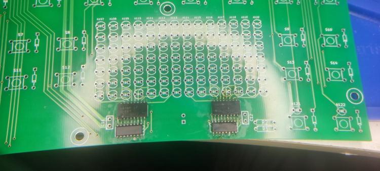
Another very important step is test for continuity between each pin, following the traces they lead to.
Most of the pins between the shit register ICs and resistor networks are directly connected vertically as you can see in the picture above.
For the other pins follow the traces which lead to pads and via testing holes and probe between them.
Failure to do this may lead to less not lighting and encoders not working.
-
Drilling the mounting holes for the Front Panel
-
1 hour ago, latigid on said:
You could try to bodge it by connecting the cathode end of the diode directly to the encoder switch pin. It is the one closer to the middle of the board (the one closer to the edge is the row sink and is common to the three preceding encoders). It would probably help to remove the encoder switch pin from the PCB totally and find some way to insulate it.
Connecting directly from encoder switch pin to J2 pin 6 is also an option.
Connecting the diode from the Encoder Switch pin to J2 pin 6 solved the issue!
There must be a short on the top side of the board under or near ENC4!
Thanks so much for the help, and enjoy a beer on me! Must have been the longest troubleshooting effort ever! :) -
My guess is theres a short under ENC4 somewhere but I'm finding it too difficult to desolder.
At this stage I may just order 10 encoders from midiphy with a plate PCB. -
Not exactly sure how useful this info is, but I de-soldered the positive leg of this Diode and the issue seems to go away, ENC4 turns normally without lighting up the SW20's LED.
-
11 minutes ago, latigid on said:
If you essentially trigger the encoder pins with the plate PCB disconnected and there is no spurious matrix event, then I agree that there is a short somewhere on the plate board. It is really puzzling that you don't see any short to J2 from the encoder.
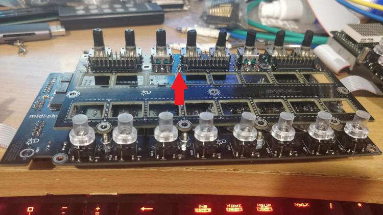
Check again that all RNs are cut flush, even with stacking headers maybe the pins are too long?
The encplate PCB is fairly simple and just connects the encoders to J1/3 and the diode columns to J2.
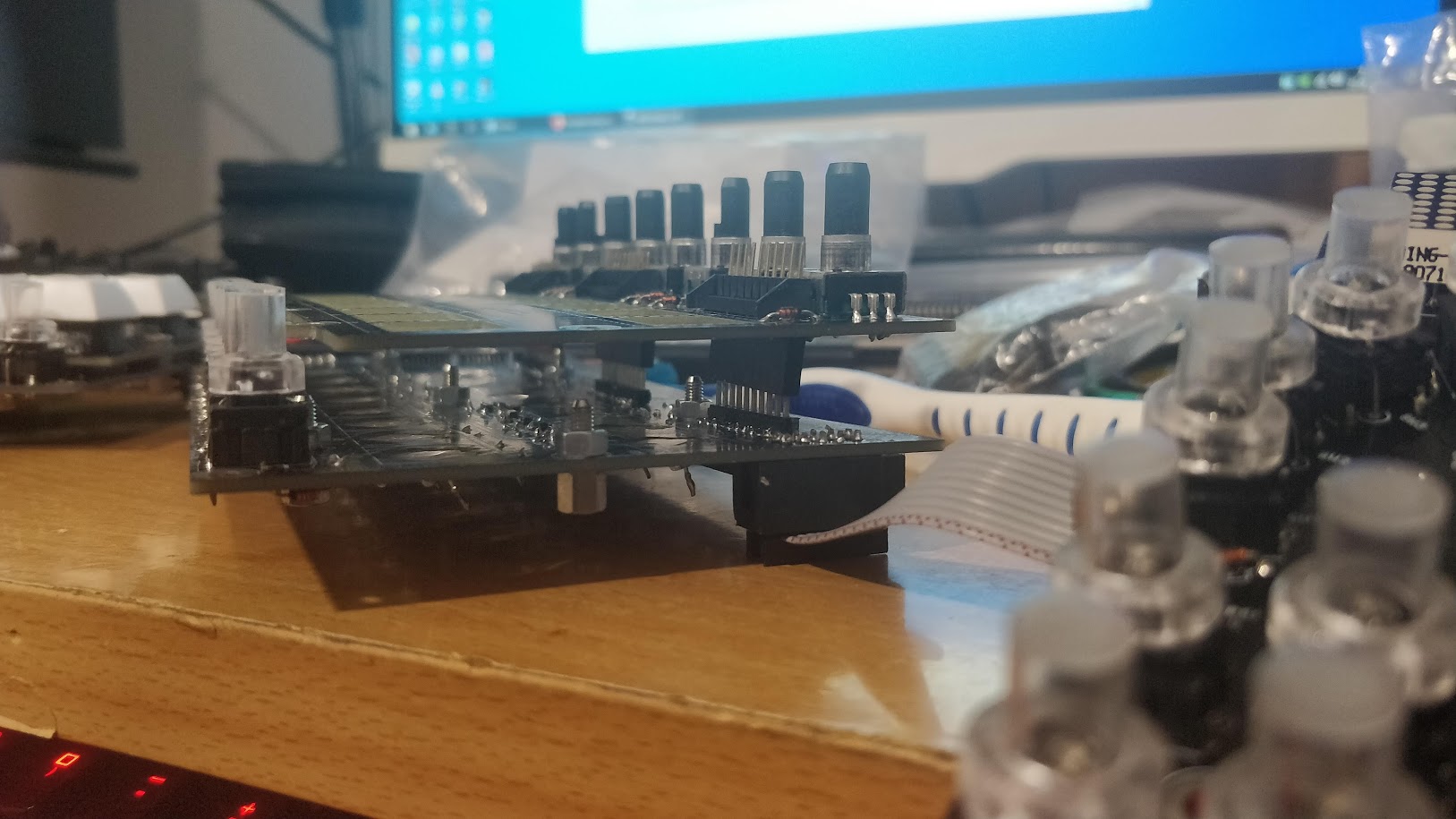
The RN pins are definitely not touching, here's a photo showing how far the PCBs are apart from each other with the headers:

Shorting J1 Pin 8 to GND even at that distance causes SW20 to illuminate.
Any advice or images of traces to help me find the short on the Enc Plate PCB?
On the underside of the PCB there is quite a few spots where the silkscreen has been marked and copper is showing. No traces seem to be exposed however.
-
On 6/15/2021 at 5:44 PM, latigid on said:
I still think if you have a short between the encoder pins and J2, pin 6, that would probably explain your issue.
Try shorting J1 pins 8/9 to 0V, (not 10). That's where that encoder ends up. You should see DIN events corresponding to the encoder if SEQ_L/R is loaded. See if enabling the DIN matrix brings back the LED storm too.
Another weird thing that sometimes happens is that your MEC switches have broken LEDs.
Still no short between ENC4 pins and J2 Pin 6.
With the ENC Plate PCB installed when I short J1 pin 8 to GND the SW20 LED lights up and I get the following in debug, it includes touching the pin and releasing from it:
[1036341.011] MBNG_MATRIX_NotifyToggle(1, 28, 0)
[1036341.011] MBNG_DIN_NotifyToggle(2028, 0)
[1036341.012] [EVENT] id=BUTTON:2028 hw_id=BUTTON:2028 bank=0 fwd_id=LED:2031 type=NoteOn value=0 label=
[1036341.013] MBNG_DOUT_NotifyReceivedValue(2031, 127)
[1036341.014] MBNG_MATRIX_DOUT_NotifyReceivedValue(2, 31, 127)
[1036341.015] MBNG_MATRIX_NotifyToggle(1, 44, 0)
[1036341.016] MBNG_DIN_NotifyToggle(2044, 0)
[1036341.016] No event assigned to BUTTON hw_id=2044
[1036341.020] MBNG_MATRIX_NotifyToggle(1, 60, 0)
[1036341.021] MBNG_DIN_NotifyToggle(2060, 0)
[1036341.021] No event assigned to BUTTON hw_id=2060
[1036341.024] MBNG_MATRIX_NotifyToggle(1, 12, 0)
[1036341.024] MBNG_DIN_NotifyToggle(2012, 0)
[1036341.025] [EVENT] id=BUTTON:2012 hw_id=BUTTON:2012 bank=0 fwd_id=LED:2016 type=NoteOn value=0 label=
[1036341.026] MBNG_DOUT_NotifyReceivedValue(2016, 127)
[1036341.027] MBNG_MATRIX_DOUT_NotifyReceivedValue(2, 16, 127)
[1036341.029] MBNG_MATRIX_NotifyToggle(1, 36, 0)
[1036341.030] MBNG_DIN_NotifyToggle(2036, 0)
[1036341.030] No event assigned to BUTTON hw_id=2036
[1036341.033] MBNG_MATRIX_NotifyToggle(1, 52, 0)
[1036341.034] MBNG_DIN_NotifyToggle(2052, 0)
[1036341.034] No event assigned to BUTTON hw_id=2052
[1036341.038] MBNG_MATRIX_NotifyToggle(1, 4, 0)
[1036341.038] MBNG_DIN_NotifyToggle(2004, 0)
[1036341.039] [EVENT] id=BUTTON:2004 hw_id=BUTTON:2004 bank=0 fwd_id=LED:2015 type=NoteOn value=0 label=
[1036341.040] MBNG_DOUT_NotifyReceivedValue(2015, 127)
[1036341.041] MBNG_MATRIX_DOUT_NotifyReceivedValue(2, 15, 127)
[1036341.042] MBNG_MATRIX_NotifyToggle(1, 20, 0)
[1036341.042] MBNG_DIN_NotifyToggle(2020, 0)
[1036341.043] [EVENT] id=BUTTON:2020 hw_id=BUTTON:2020 bank=0 fwd_id=LED:2024 type=NoteOn value=0 label=
[1036341.044] MBNG_DOUT_NotifyReceivedValue(2024, 127)
[1036341.045] MBNG_MATRIX_DOUT_NotifyReceivedValue(2, 24, 127)
[1036341.060] MBNG_MATRIX_NotifyToggle(1, 20, 1)
[1036341.060] MBNG_DIN_NotifyToggle(2020, 1)
[1036341.062] [EVENT] id=BUTTON:2020 hw_id=BUTTON:2020 bank=0 fwd_id=LED:2024 type=NoteOn value=127 label=
[1036341.062] MBNG_DOUT_NotifyReceivedValue(2024, 0)
[1036341.063] MBNG_MATRIX_DOUT_NotifyReceivedValue(2, 24, 0)
[1036341.070] MBNG_MATRIX_NotifyToggle(1, 20, 0)
[1036341.070] MBNG_DIN_NotifyToggle(2020, 0)
[1036341.071] [EVENT] id=BUTTON:2020 hw_id=BUTTON:2020 bank=0 fwd_id=LED:2024 type=NoteOn value=0 label=
[1036341.072] MBNG_DOUT_NotifyReceivedValue(2024, 127)
[1036341.073] MBNG_MATRIX_DOUT_NotifyReceivedValue(2, 24, 127)
[1036341.080] MBNG_MATRIX_NotifyToggle(1, 12, 1)
[1036341.080] MBNG_DIN_NotifyToggle(2012, 1)
[1036341.082] [EVENT] id=BUTTON:2012 hw_id=BUTTON:2012 bank=0 fwd_id=LED:2016 type=NoteOn value=127 label=
[1036341.082] MBNG_DOUT_NotifyReceivedValue(2016, 0)
[1036341.083] MBNG_MATRIX_DOUT_NotifyReceivedValue(2, 16, 0)
[1036341.088] MBNG_MATRIX_NotifyToggle(1, 12, 0)
[1036341.088] MBNG_DIN_NotifyToggle(2012, 0)
[1036341.089] [EVENT] id=BUTTON:2012 hw_id=BUTTON:2012 bank=0 fwd_id=LED:2016 type=NoteOn value=0 label=
[1036341.090] MBNG_DOUT_NotifyReceivedValue(2016, 127)
[1036341.091] MBNG_MATRIX_DOUT_NotifyReceivedValue(2, 16, 127)
[1036341.186] MBNG_MATRIX_NotifyToggle(1, 44, 1)
[1036341.186] MBNG_DIN_NotifyToggle(2044, 1)
[1036341.186] No event assigned to BUTTON hw_id=2044
[1036341.192] MBNG_MATRIX_NotifyToggle(1, 52, 1)
[1036341.193] MBNG_DIN_NotifyToggle(2052, 1)
[1036341.193] No event assigned to BUTTON hw_id=2052
[1036341.197] MBNG_MATRIX_NotifyToggle(1, 4, 1)
[1036341.197] MBNG_DIN_NotifyToggle(2004, 1)
[1036341.198] [EVENT] id=BUTTON:2004 hw_id=BUTTON:2004 bank=0 fwd_id=LED:2015 type=NoteOn value=127 label=
[1036341.199] MBNG_DOUT_NotifyReceivedValue(2015, 0)
[1036341.200] MBNG_MATRIX_DOUT_NotifyReceivedValue(2, 15, 0)
[1036341.201] MBNG_MATRIX_NotifyToggle(1, 20, 1)
[1036341.201] MBNG_DIN_NotifyToggle(2020, 1)
[1036341.203] [EVENT] id=BUTTON:2020 hw_id=BUTTON:2020 bank=0 fwd_id=LED:2024 type=NoteOn value=127 label=
[1036341.203] MBNG_DOUT_NotifyReceivedValue(2024, 0)
[1036341.204] MBNG_MATRIX_DOUT_NotifyReceivedValue(2, 24, 0)
[1036341.205] MBNG_MATRIX_NotifyToggle(1, 36, 1)
[1036341.206] MBNG_DIN_NotifyToggle(2036, 1)
[1036341.206] No event assigned to BUTTON hw_id=2036
[1036341.210] MBNG_MATRIX_NotifyToggle(1, 60, 1)
[1036341.211] MBNG_DIN_NotifyToggle(2060, 1)
[1036341.211] No event assigned to BUTTON hw_id=2060
[1036341.215] MBNG_MATRIX_NotifyToggle(1, 12, 1)
[1036341.215] MBNG_DIN_NotifyToggle(2012, 1)
[1036341.217] [EVENT] id=BUTTON:2012 hw_id=BUTTON:2012 bank=0 fwd_id=LED:2016 type=NoteOn value=127 label=
[1036341.217] MBNG_DOUT_NotifyReceivedValue(2016, 0)
[1036341.218] MBNG_MATRIX_DOUT_NotifyReceivedValue(2, 16, 0)
[1036341.219] MBNG_MATRIX_NotifyToggle(1, 28, 1)
[1036341.219] MBNG_DIN_NotifyToggle(2028, 1)
[1036341.221] [EVENT] id=BUTTON:2028 hw_id=BUTTON:2028 bank=0 fwd_id=LED:2031 type=NoteOn value=127 label=
[1036341.221] MBNG_DOUT_NotifyReceivedValue(2031, 0)
[1036341.222] MBNG_MATRIX_DOUT_NotifyReceivedValue(2, 31, 0)
This does not happen without the Enc plate PCB installed / connected.
I also tried doing it with the arduino headers installed to separate the PCBs further like in the photo below, and I do get the events and SW20's LED lighting up still.

So this should rule out a short between components touching on both boards.
Shorting J1 Pin 9 to GND has no effect.Would I be right in thinking there's a short somewhere on the ENC Plate PCB?
-
On 6/10/2021 at 11:30 PM, latigid on said:
hw_id=36 means that it is the 36th DIN input. I think the DINs are counted backwards, so that corresponds to IC3, pin 14. That pin is connected in parallel to J2, pin 6 and RN2, pin 5, along with the diode anodes of that column. (If they are counted forwards, then it is IC3 pin 3 and J2/RN2 pin 7 and the 5th column of diodes.)
Logically, the only way that you can trigger that DIN pin by turning EN4 is if there is some connection between the encoder pins and that pin. It could also be the diodes in the 4th column of switches.
With the plate board connected, see if you get any shorts between the encoder legs and all pins of J2.
Disconnect the plate and try the same debug test by shorting J1 pins 9/10 to 0V. If you get the same hw_id=36, then your issue is on lemec_R. If the issue disappears when disconnecting, then there is some unintentional contact made when stacking the boards together.
So i tested for shorts between all encoder legs of ENSW4 and the pins of J2 - nothing.
Disconnected the plate PCB and shorted pins 9 and then 10 of J1 to GND. Nothing comes up on Debug. (I even removed the comment # character from the DIN line in seq_r.ngc and tried a second time just in case. -
I set it up in RH mode (from left to right: Core -> LE MEC -> LE MEC RH -> JA PCB )
and loaded up seq_r and the issue remained.
I commented out the DIN MATRIX line in seq_r.ngc for the RH PCB and this is the result of turning ENCSW4 clockwise one detent with set debug on:[ 657.687] MBNG_DIN_NotifyToggle(36, 0) [ 657.688] No event assigned to BUTTON hw_id=36 [ 657.702] MBNG_ENC_NotifyChange(12, 1) [ 657.703] [EVENT] id=ENC:12 hw_id=ENC:12 bank=0 fwd_id=DISABLED:0 type=CC value=0 label= [ 657.708] MBNG_DIN_NotifyToggle(36, 1) [ 657.709] No event assigned to BUTTON hw_id=36I noticed SW20 did not light up this time when turning. The Mattias LEDs Common Cathode are still desoldered, so not sure if these would light up in this column with DIN commented out.
I presume I was not meant to comment out DOUT_MATRIX?
Thanks!
-
I've just replaced IC3 and IC4 on the LEMEC RH PCB and no luck unfortunately.
Damn you short, where are you!
.jpg.e3b31104ff96e741dd8d1ae982e96525.jpg)
.jpg.bc1e505d3f62ae939d592be10b41346b.jpg)
.jpg.2cf6c1bf3cc623526f90d47618e61289.jpg)
.jpg.1f7384a394a5b3b41ca6f6a471f69197.jpg)
.jpg.55f0b4f3cd47d60c2e7d01c9758743ba.jpg)
.jpg.d927fca8220680948a534684f99817e9.jpg)
.jpg.3e7da82198ffab693253fdaf2644c1cb.jpg)
.jpg.882acda10f2d641671adeb108794d2e4.jpg)
.jpg.11e73cdb94019f5f36ac65ec48d67303.jpg)
.jpg.0850b0cedac750d42a46af2e54d1e869.jpg)
.jpg.0eccbfc425b2b84c8a735260792264c2.jpg)
.jpg.75e29f195e85d8297c5c56cf9f7ccc17.jpg)

MIDIbox Quad Genesis
in MIDIbox FM
Posted · Edited by Smithy
Just found a cheap source on AliExpress for the m3 threaded inserts for wood:
https://a.aliexpress.com/_EwPghFj
Be sure to select m3xm5x6mm