

Imp
-
Posts
419 -
Joined
-
Last visited
-
Days Won
4
Content Type
Profiles
Forums
Blogs
Gallery
Everything posted by Imp
-
Eine Diode lässt erst durch, wenn ihre minimale Vorwärtsspannung (ca. 0.7V) überschritten wird. Du muss eigentlich nur dein Eingangssignal mit nem op-amp puffern, also vom eigentlichen Signal isolieren, damit es dieses nicht beeinflusst. Dabei kannst du es auch mit einem Poti so skalieren, dass der (Original-)Pegel der zu clipping führt,hinterher halt diesen 0.7V entspricht. Wenn du damit einen Transistor ansteuerst, hast du quasi eine Schalter, der immer dann an ist, wenn dein Signal übersteuert. In den Plänen für VU-Meter sind so mit meheren Dioden hintereinander die verschiedenen Spannungsstufen realisiert. Wenn du das auf eine Stufe reduzierst, müsste das trotzdem funktionieren.
-
Ich glaube mit "clipping-LED" meint er eine LED, die anzeigt, ob der Eingang übersteuert wird. Ein abgespecktes VU-meter quasi. Aber auch das sollte mit nem Op-amp gepuffert werden. Hier sind ein paar Pläne für vollständige VU-meter, die haben dann auch ein Poti am Eingang, um die Empfindlichkeit an den Pegel anzupassen.
-
That is a problem, because then you won't be able to repair it, if necessary. The sammich is properly developed and reliable, but it's meant for DIY and therefore requires DIY-skills in the long run. Not kosher at all, IMHO. Building that thing is part of the experience! And it isn't that hard, especially with this community. Just DIY, it's totallly worth it!
-
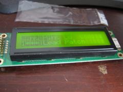
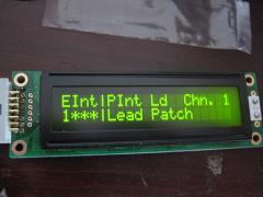
In both datasheets, there is a schematic under 4.2 which shows how to connect the driving voltage. It's quite hidden...I'd missed that one too.. The 2nd display needs positive voltage, as Vo is connected to a voltage dividing pot between Vdd(+) and ground.
-
Have you checked the Pic-ID? Mios can be set to use different display-drivers via this ID. You can reset it to all zeros with the change_id app found here under troubleshooting.
-
I was referring to the c64-powerplug (lower left corner), which has 7 Pins, but only 4 of them are connected to the circuit. The symbols on the right of the cicuit (14vdc, 5vdc) represent the outputs, which can be wired to another plug, or directly to the LED/ to the Core/the SIDs, if the circuit is inside the same enclosure as those modules.
-
Since the PSu provides 5V Dc, u can leave out the rectifier on the core and use it for this circuit. You'll need one additional 7809 and these caps. The size of the resistor depends on the LED (which is optional btw.)and it's desired brightness. The Value means 220Ohm. The plug is a Din-plug with 7 pins, but you could also cut the cord and use any plug/socket combination you like, as long as it has at least 4 pins.
-
Welcome on board! The Lcd should work, as it is quite similar to the one i used. The shematic for the optimized psu is meant as an (necessary) addition to the c64-psu. The c64-psu puts out regulated 5V, which is fine as it is for the core(s). It also puts out 9V AC(<--) which has to be rectified (part x1) and regulated to 9v DC(part 7809). These 9V then get added to the already present 5V to have 14V DC. While this is meant to provide enough voltage to get regulated 12V for the older SIDs, it can also be regulated down to a stable 9V again, which happens on the SID-modules. I think, most people who take the modular route also build the CS on breadboard. It's possible to combine smash'S ( Wilba's actually) CS-pcb with other modules, but it's usually used as part of a mb-6582. Keep in mind, that you can always upgrade your CS later on!
-
From the album: imp`s Zeug
-
From the album: imp`s Zeug
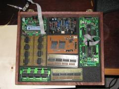
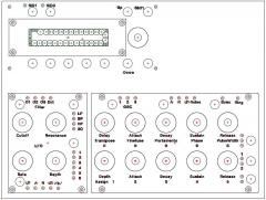
The guts minus the dreaded spaghettiness still to come... It's obviously the modular approach, with modules from Smash and Mike, and Seppoman's ssm2044 Filter, controlled by one Aout_LC. -
From the album: imp`s Zeug
-
From the album: imp`s Zeug
-
From the album: imp`s Zeug
I printed this, doublechecked for scale, taped it on the brass, and marked the holes before finally drilling them. -
From the album: imp`s Zeug
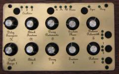
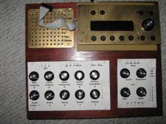
Just to fiddle with the layout, the design is not the final one.... -

From the album: imp`s Zeug
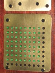
A part of the modmatrix. I made it by ironing on Press'n'Peel and then etching it in Copper sulfate. As you see, it has not worked so well... -
From the album: imp`s Zeug
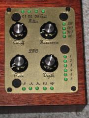
This is the backside of the etched panel, i just flipped it over instead of drilling all those holes again... -
From the album: imp`s Zeug
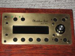
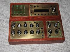
My SID, still WIP but nearly complete the Panel is made of brass with laserprinted film I have made this in my bathroom...so no real workshop was involved ;) -
From the album: imp`s Zeug
-
From the album: imp`s Zeug
-
The info you need is in here, under "Analog Control Elements". You can use 5 inputs per pic, no multiplexing. I think this extension only makes sense in combination with some analog gear. Edit: Maybe Shuriken is right about 1), I just thought, if the modular SID can handle CV inputs, the MB6582 should too, but maybe it doesn't...
-
Just sum up the left and right channel to one mono-channel. You can do this without any active circuitry. Just tie the outputs togethter. A pluggable stereo to mono adapter, or Y-cable does the trick.
-
SIDSynth testing,watch the video and tell me
Imp replied to GordTheRogue's topic in Testing/Troubleshooting
You schould have used a PIC18F4685 instead. Look Here -
Da klickste mal am besten ganz oben links auf dieser Seite auf ucapps.de, da sind (fast) alle Informationen die du brauchst. Dort ist zwar alles auf englisch, aber da musst du wohl durch. Zur not hilft dir der Google-Übersetzer. Wenn du noch Fragen hast, durchforste mal dieses Forum, ob die vielleicht schon beantwortet wurden. Bei der Menge an gebauten Kisten stehen die Chancen ganz gut, dass dein Problem / deine Frage schonmal aufgetreten ist Du kannst auch mal nach dem Sammich-Sid suchen, das ist ein komplettes Kit und erspart dir einiges an Planung und Ärger, aber auch an Gestaltungsfreiheit... Auch wichtig: Verkauft werden komplette Projekte nur nur in Ausnahmefällen, Selberbauen ist schon der richtige Weg. Edit: Bezugsquellen stehen auf ucapps.de unter MBHP Projects-->MIDIbox SID V2 Synth-->Walkthrough du musst mindestens mit nem Hunni rechnen, mehr geht leichter als weniger ;)
-
Die Software wäre natürlich die einfachste Lösung, aber wenn du dein Projekt ohne Pc verwenden können willst, kannst du sowas auch als Hardware realisieren. Die Rollen, die die Bewegung des Balls weiterleiten sind mit optischen Encodern verbunden. Du müsstest dann an diesen encodern das Signal abzweigen. Die Drehregler die in Projekten wie z.b. dem Sid oder dem Seq verwendet werden sind auch Encoder. Für dein Vorhaben wäre die Midibox64E das Richtige. Ich weiß aber nicht, inwiefern die Software noch angepasst werden muss. Zu dem Thema ist vielleicht auch Rasteri's Scratchwheel interessant, weil das auch optisch funktioniert.