

latigid on
-
Posts
2,524 -
Joined
-
Last visited
-
Days Won
149
Content Type
Profiles
Forums
Blogs
Gallery
Posts posted by latigid on
-
-
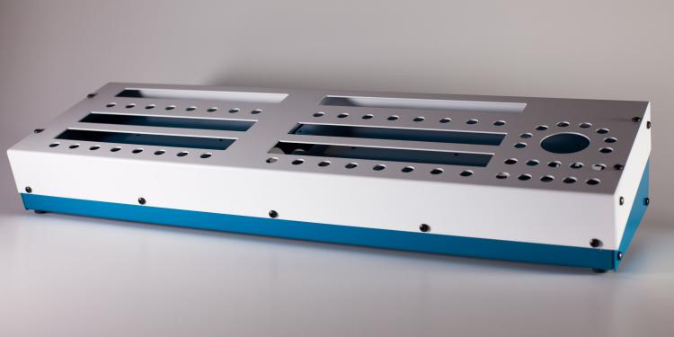
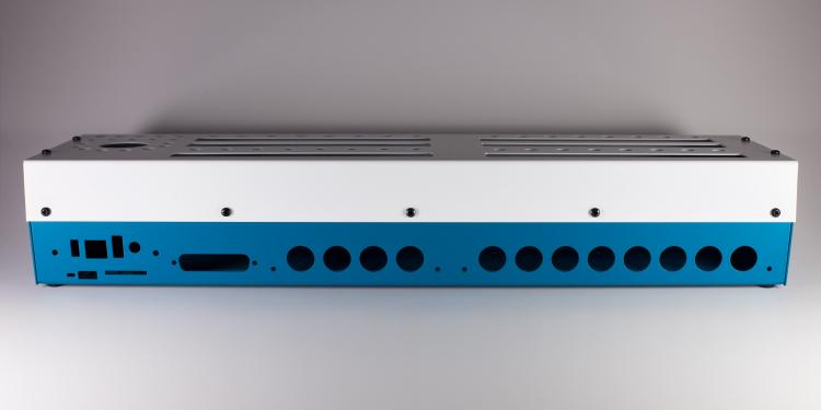
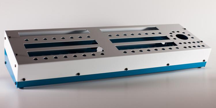
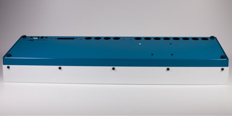
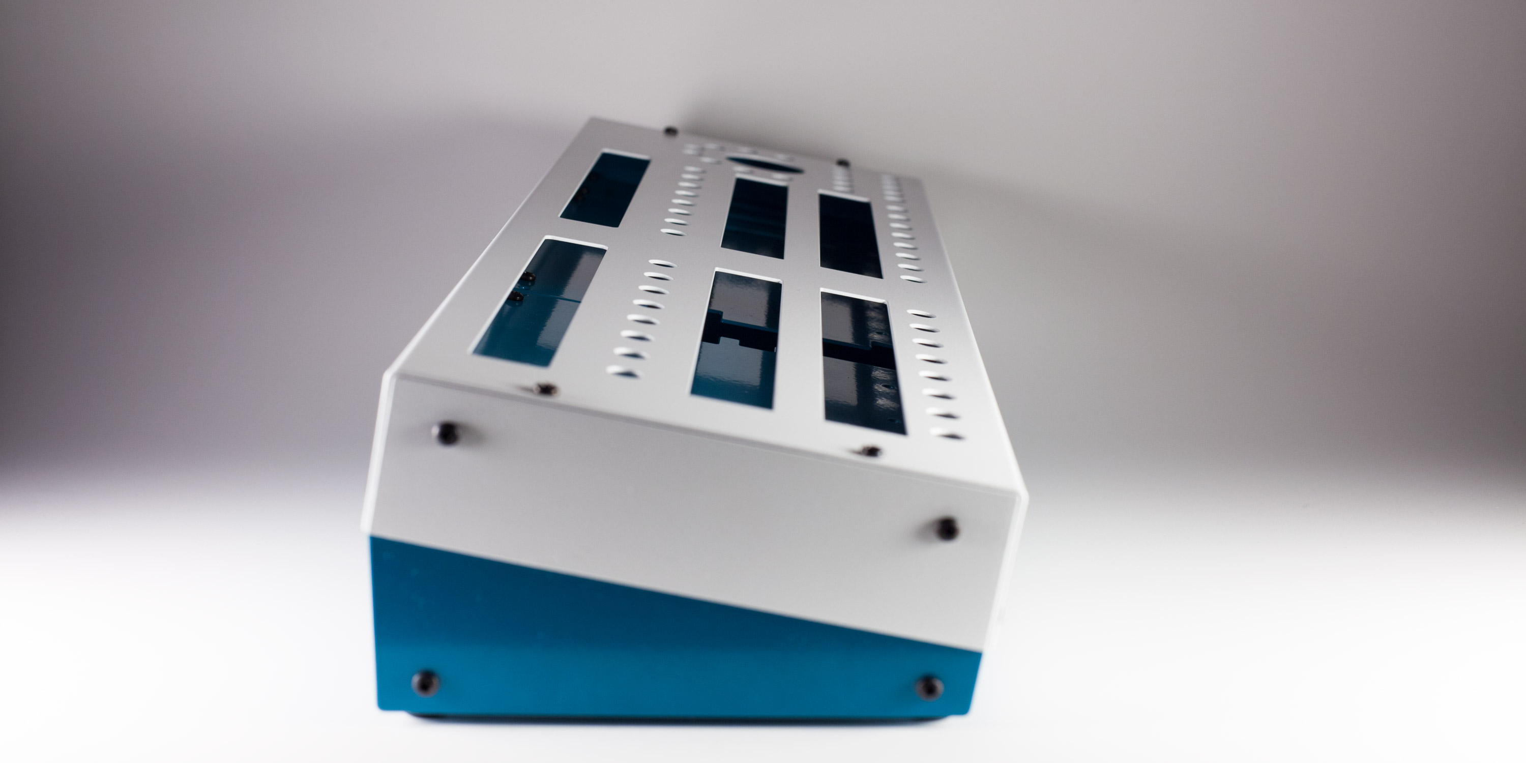
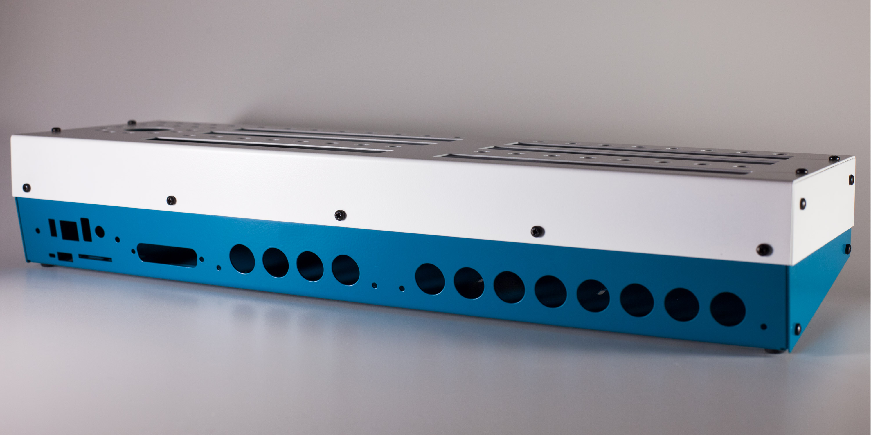
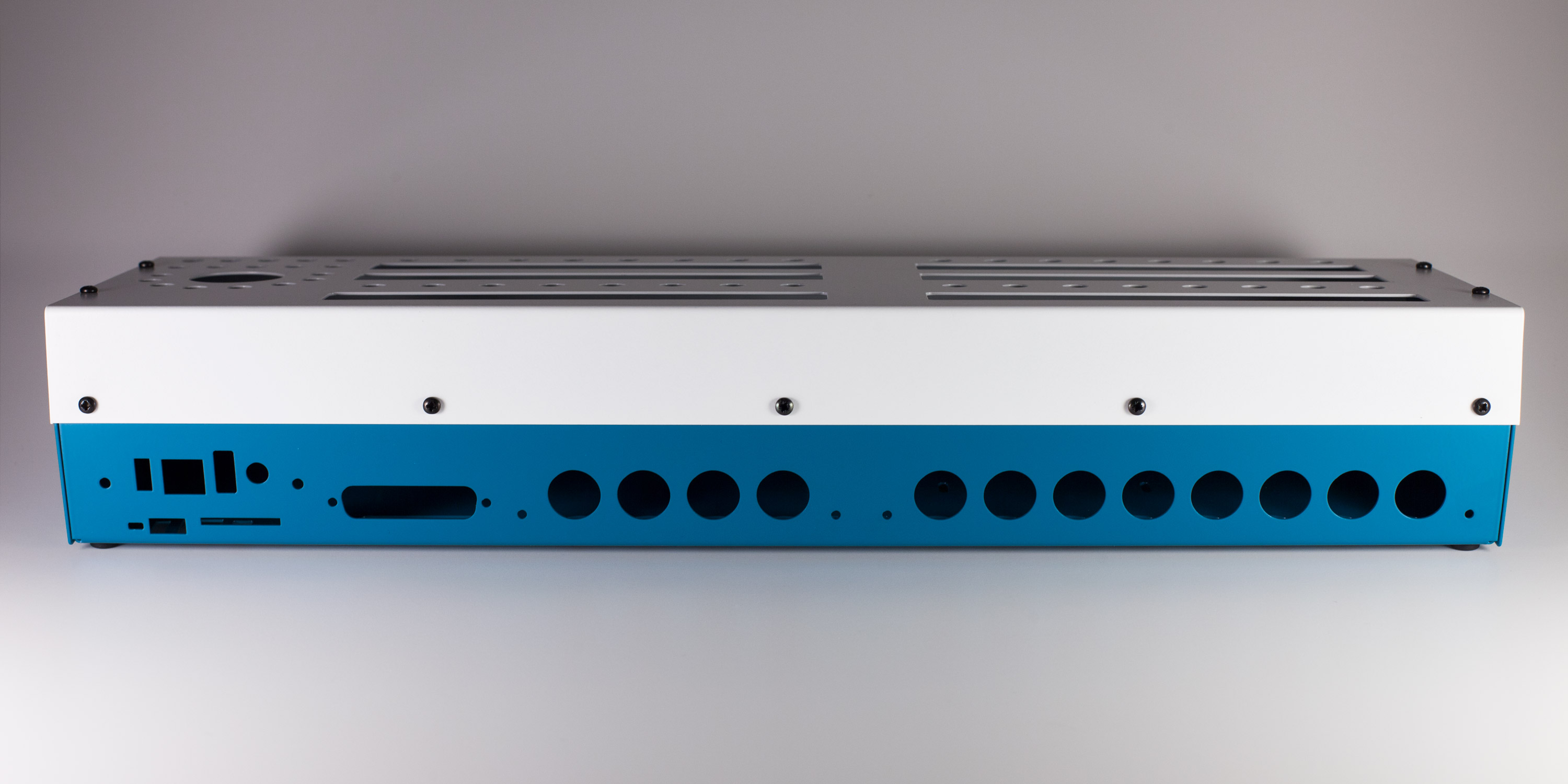
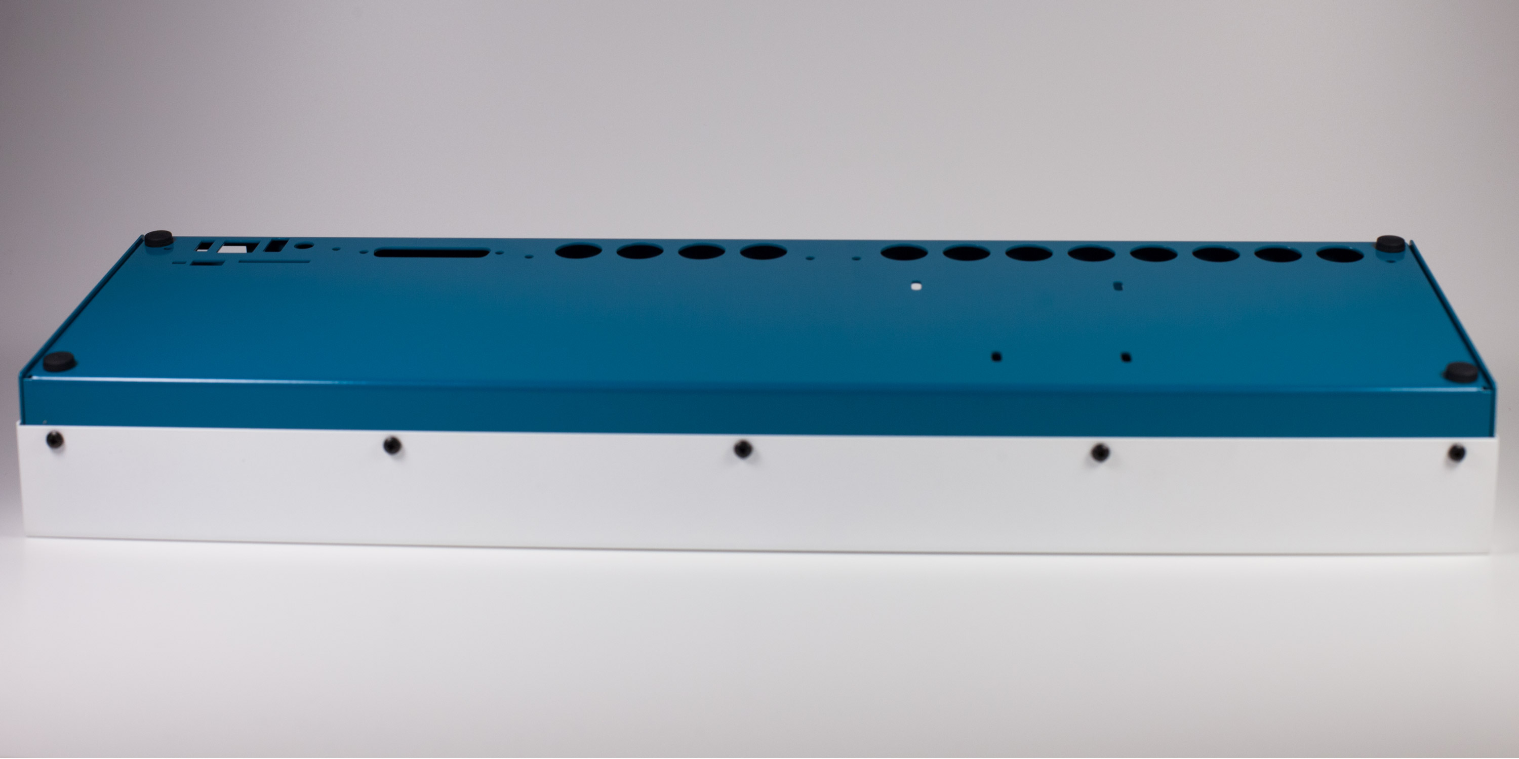
Case protos are in (thanks @Hawkeye for the pics!)
This means we won't be in time for spring, but with luck it won't be too long before the project is ready to go.
Best,
Andy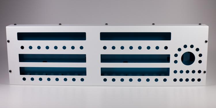


-
 1
1
-
-
Well then. The ability to reroute single-channel poly info to MPE across 16 channels of a port would be cool and a good use of all of those MIDI ports!
;)
-
MPE has now been standardised:
https://www.midi.org/specifications-old/item/the-midi-1-0-specification
Anyone keen to write MIDIbox drivers for it ? ;-)
-
-
What Core version? J4A is the I2C port.
-
I2C if required.
-
There they are! Many thanks!
-
Again, the email notifications are not being sent...
-
This was a great project to do, as Peter had a clear concept in mind from the start from his previous prototypes. We spent several weeks discussing the possible hardware features and figuring out how we'd source the parts. The hardware design took about a month or so, sped up by the fact that I was reusing some of the SEQ hardware elements. The initial tests were fine, although getting the boards stacked was a puzzle of headers! All sorted now.
Peter is one of the nicest and most enthusiastic people I know. He's being modest (as usual). The case design he did himself 100%, I even made him extract the SVGs from the PCB gerbers! The software, although built on a very solid base provided by TK., took lots of extra work, especially coding the display, various bug squashing etc.
Good work all around!
-
and does it work? Did you save/store the changes then reupload _NG?
-
I received a short update from Adrian that he had an unexpected callup. Things are still in progress and we'll update as soon as we know what's what.
-
Looks to be the correct one. The supply is +5V as noted a few posts above, so no changes needed to the BOM. You will have to upload the bootloader hex and change the display type though.
-
-
Hehe, LoopA proto is just out of shot :). Nice sounds and arrangement!
-
Just a few notes on SMT soldering. The process can be a whole lot quicker than THT, as you never need to clip a lead. It's true that you can't easily desolder chips, but the advice about hot air rework stations is sound. I've done the same before, even reusing 600 LEDs for the BLM. Practising on a test PCB is also smart.
The die inside a SOIC chip is probably the same as in a DIP. The package and leads are much smaller for SMT though, and with DIY you're normally socketing the ICs. So overheating is an issue. I suggest the "tack" method to anchor one corner, correcting the alignment then going down just one row at a time. Hold the soldering iron at a low angle (close to the PCB) if possible and heat the pad, then apply solder to the pin. This keeps the heat source away from the IC and uses surface tension to wick the solder in. I suggest against "drag soldering" as it's possible to scratch the soldermask.
For bridges, I've found an el cheapo solder sucker removes the excess quite well.
-
1
-
-
The SEQ V4+ (antilog) hardware is validated and we have some PCBs available, although the mechanism of the shop etc. is not quite ready. The last piece of the puzzle is the case, which is still in progress from Adrian.
- If you want something ready-to-go, with all through-hole compenents etc., then go for the Wilba version (contra: there's no ready-made case available and CNC-routed panels are quite expensive). SEQ V4+ features should be compatible with all STM32F4 versions; this includes both the Wilba and antilog variants.
-
if you don't mind waiting a bit and want a "high-quality" solution/enhanced hardware suited to the current SEQ workflow, then the SEQ v4+ is the right way to go.
- it does involve SMT soldering, although it is not super difficult being 1206/SOIC. The Wilba version is certainly more straightforward in terms of the main control surface.
- the case from Adrian will make a "complete unit," hence we wait to see what Adrian brings :)
-
2
-
Hi,
I thought it was around somewhere :) for LPC. Sorry about the outdated doku,,,
Could you please try with the attached files? We need to get @TK.'s attention to get a proper build in the SVN.
There may be a problem with MIDI; in this case try:
SESSIONS/DEF_V4L/MBSEQ_C.V4 file: Old: MIDI_BUS_Options 0 0x00 New: MIDI_BUS_Options 0 0x01 -
3 hours ago, Phatline said:
one aout-module is not functional > looks i killed the dac somehow.
Many have done the same. Some of the DACs seem quite sensitive to heat, which can result in a fully nonfunctional AOUT or weirdness on some channels.
3 hours ago, Phatline said:but in bipolar mode it is only working from -+3V
Could be the known issue of a 1:1 voltage divider:
But it's already claimed to be okay for the quad VCA, if that's your usecase.
-
Notifications have also not been working for a while. @Hawkeye may be able to help.
-
http://www.ucapps.de/ has the info you need.
Best,
Andy -
Okay, so you want to record incoming note data and output that on a particular MIDI port.
First, is your track set up to output on the correct MIDI channel?
http://wiki.midibox.org/doku.php?id=mididocs:seq:beginners_guide:start#track_eventTo get something working initialise the track; you should get four steps of C3. Make sure that will play on the configured output. You can enter basic notes with the GP buttons and encoders.
To record, use the following:
http://wiki.midibox.org/doku.php?id=mididocs:seq:beginners_guide:start#entering_notesIt takes a bit more effort, but should work.
If things are not working properly, there may be an issue with your soldering or a MIDI feedback loop (the outputting controller is receiving the same data it's sending).
-
What are you trying to do? Set up for live recording? If you just want to forward the MIDI IN -> OUT, set up a router node as shown in the guide above.
-
-
Really cool, both the tune and the build!


MBSEQ V4 build with MIDI, CV and DIGITAL OUT
in MIDIbox SEQ
Posted
Awesome, well done!