

latigid on
-
Posts
2,524 -
Joined
-
Last visited
-
Days Won
149
Content Type
Profiles
Forums
Blogs
Gallery
Posts posted by latigid on
-
-
It's never too early!

-
Doing a bit of spring cleaning, maybe these might be of interest. Prices in euro plus shipping
-
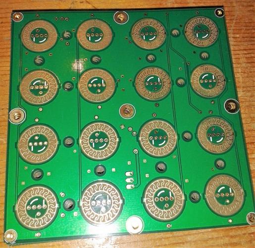
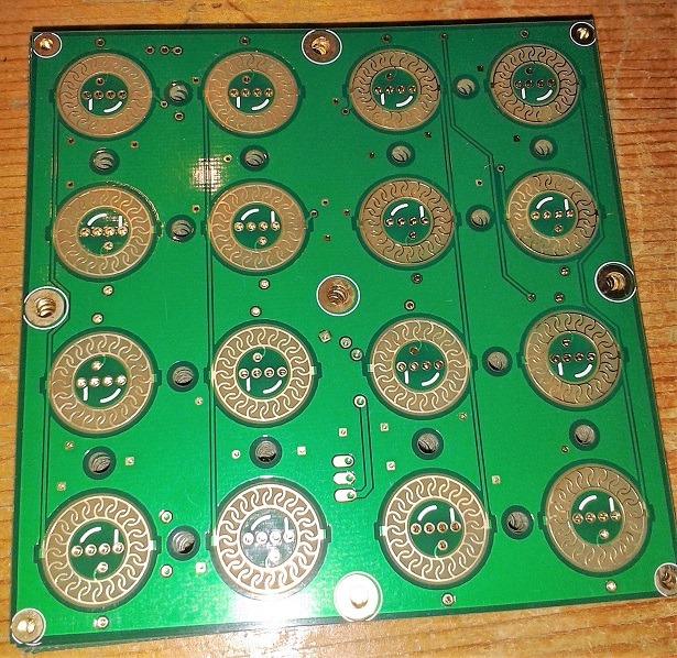
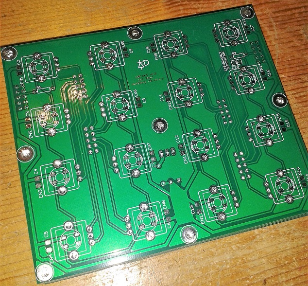
- Pads WS2812 LEDs and Sparkfun silcone buttons/matrix
- Availability: 10
- Price: 8
- Encs WS2812 LEDs and illuminated encoders
- Availability: 10
- Price: 10
- encoders: 1.5 each
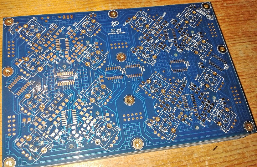
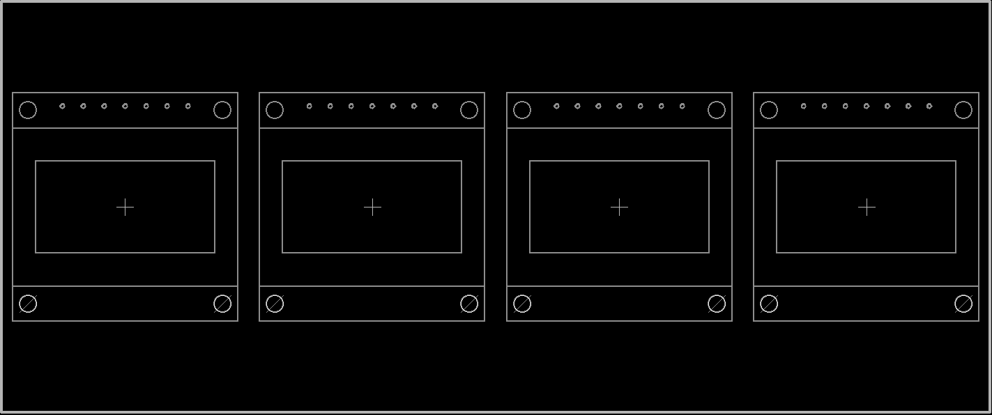
- ELO WS2812 LEDs, illuminated encoders, optional touch sensors, OLED displays mounted at 45 degrees
- Availability: 13
- Price: 20 (it's a four-layer board...)
- encoders: 1.5 each
- 0.96" white OLED: 5 each
-
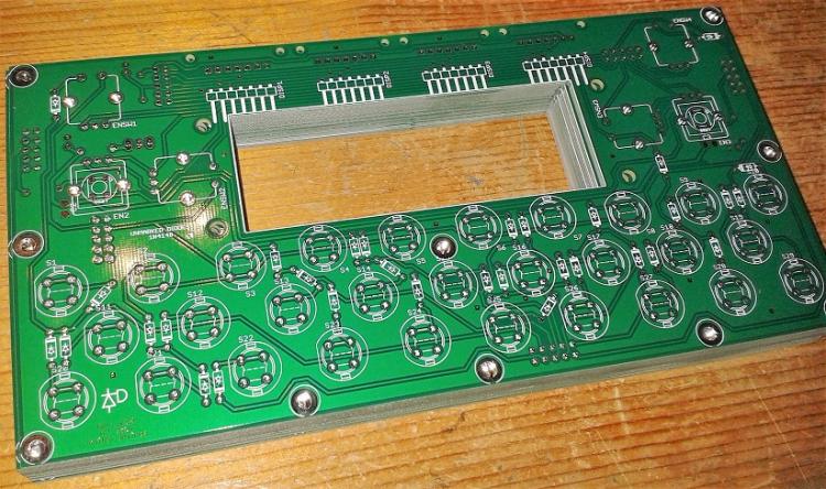
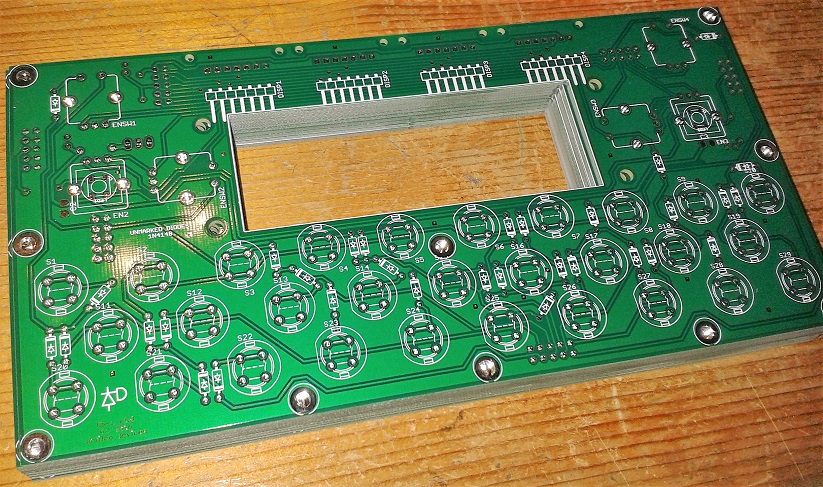
- CS1 button matrix, encoders (some illuminated), LCD/OLED mounting
- Availability: 8
- Price: 12
-
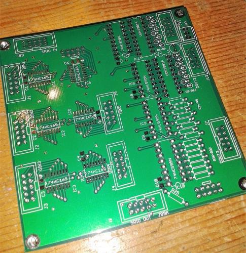
- DIN6DOUT4 SRIO, works well with Pads, Encs and CS1. Level shifter for 16 outputs (e.g. higher-voltage gates etc.)
- Availability: 9
- Price: 6
-
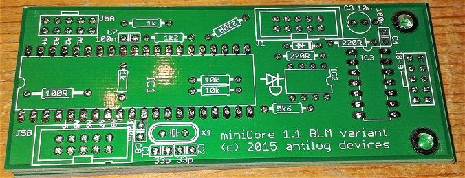
- MiniCore PIC, designed for BLM but could be useful elsewhere
- Availability: 3
- Price: 5
-
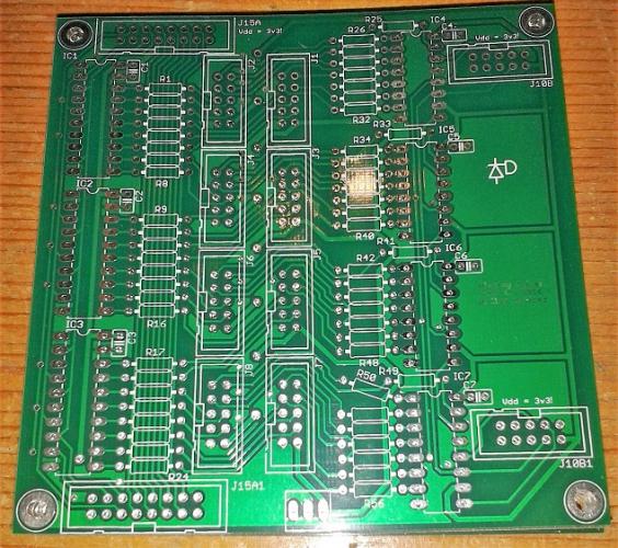
- Disp. driver buffers and CS lines for OLED displays (32 per PCB). Works, but J15 connector is mirrored...
- Availability: 8
- Price: 5 or 2 with any other purchase
-
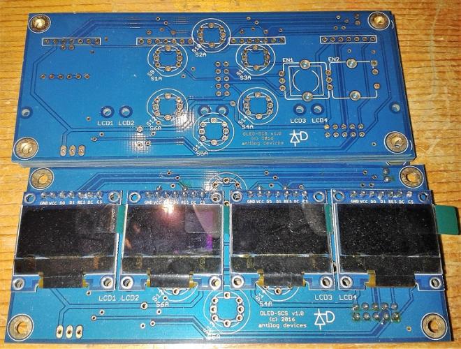
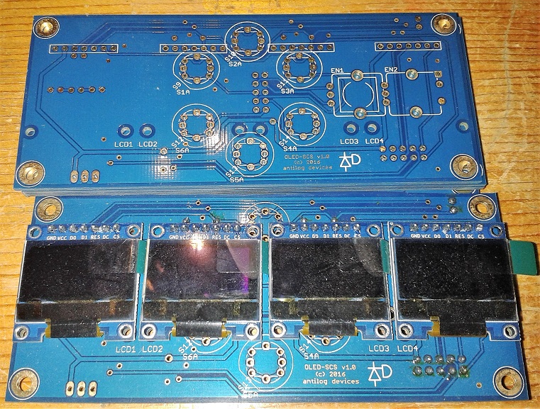
- SCS OLED many configurations possible (1-4 OLEDs, encoder and/or buttons)
- Availability: 7
- Price: 6
-
populated with 4xOLED: 25 (1 available). Looks a bit dusty, but screen protection still on

-
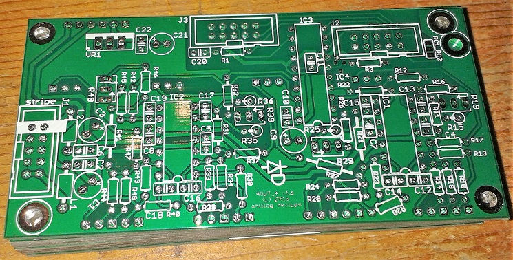
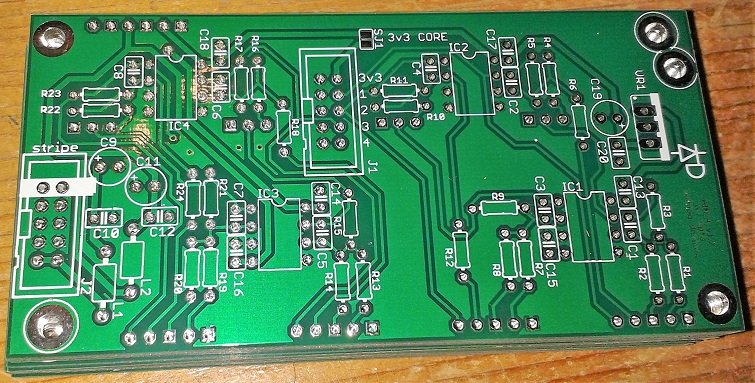
- AOUT4 MAX525-based AOUT, four channels
- Availability: 6
- Price: 5
-
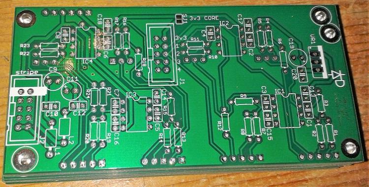
- AIN4 protection/scaling circuit interfacing to a 3V MCU, four channels
- Availability: 8
- Price: 5
-
-
Nice LEDs! What will their functions be?
Just now, Antichambre said:We can already put JPA0 on top. maybe put silkscreen too?
Done for the next PCB batch
-
Of course!
I have some PCBs arranged like this and displays in white if you need, let me know.
-
5 hours ago, Phatline said:
where to connect the "bootloader-mode" switch?
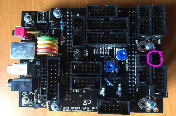
There's a two-pin header, so you can stuff a jumper or else wire some pins to a panel-mounted connector. There are a few resistors on the bottom.
-
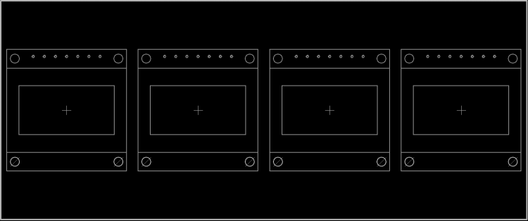
Okay, so the Nixie takes normal 5V logic signals and is powered separately with higher voltage?
If it is just a binary coded decimal, MB_NG can do that:
led_matrix_pattern=<pattern-number>	LED patterns can be specified if an event should forward its value to a LED_MATRIX element:
1: the first LED pattern specified with LED_MATRIX_PATTERN n=1 commands
2: the second LED pattern specified with LED_MATRIX_PATTERN n=2 commands
3: the third LED pattern specified with LED_MATRIX_PATTERN n=3 commands
4: the fourth LED pattern specified with LED_MATRIX_PATTERN n=4 commands
Digit1: outputs the first (rightmost) BCD digit of the value. See also cfg/test/leddig1.ngc
Digit2: outputs the second BCD digit of the value: (value / 10) % 10
Digit3: outputs the third BCD digit of the value: (value / 100) % 10
Digit4: outputs the fourth BCD digit of the value: (value / 1000) % 10
Digit5: outputs the fith BCD digit of the value: (value / 10000) % 10
LcDigit: converts the value directly into a BCD digit as used for the Logic Control protocol. See also cfg/test/leddig2.ngc
LcAuto: to handle the Logic Control protocol correctly, this pattern type will set the pattern number (1..4) according bit 5..4 of the received MIDI event value. Bit 3..0 will select the pattern position, and the 6th bit will set the "Center LED". See also cfg/test/logictrl.ngc for the usage
-
Looks ace, thanks for your work Bruno.
-
What is the pinout of a Nixie tube adaptor? It would depend on the interface: SPI, I2C, parallel etc. as how you might connect everything.
I think Nixies use voltage that can kill you, so it's not for the light-hearted.
-
Quote
the RGB button has internal resistors, so i think it's not necessary to match the color brightness...
Perfect, even easier then! Good choice on the buttons.
6 hours ago, roberto said:now i have to figure out how to assign the RGB LEDs to different velocities on the same note... phew, this coding is a big book to get into it...

It does take a while to understand the coding, but just go through the many examples. Notice in the "RGB hue sweep" thread, TK. has basically what you need. He uses a map to define the LED colour based on an incoming CC, so change that to notes over the range you require. The velocity should change the dim level, at least this is one way to work with "smart" LEDs.
-
For common anode, wire the anode to +5V or your supply voltage (possibly through a resistor) and connect your cathodes to DOUT pins. If the light output is different for each die, you may want three resistors on the cathode side instead. E.g. red has a lower Vf, so may end up brighter, often green is too bright etc., so control the current with the resistors.
595s can sink current, meaning they "can provide ground/0V." So the output is "inverted" for common anode parts. This can be specified in MB_NG. When the 595 output is high, the LED is off. When it's low, the LED is on.
You shouldn't need any transistors if the current is nominally around 20mA or so.
I haven't tried with the dim levels of normal RGB LEDs, but TK. has in your second link above.
-
Ah the fun of early release designs!
That would be something to discuss with Adrian H. I believe that he's working on including a panel to blank out the unused holes. It should be cheaper (from the supplier end) to keep track of just one design, and I think the price will be more than acceptable for end users.
-
The aim is for spring, I can't promise anything definite though.
-
-
Many thanks Bruno!

Just to note, there will be some PCB revisions for version 1.1. In general, you can consider to start getting parts together, but I would recommend waiting until the spec is validated.
Also, some of the non-Mouser parts will be offered along with PCBs. So hopefully that's only two parcels needed to ship.
-
I'm not sure if software debounce affects encoder events? We've heard a lot of stories about low-quality Bourns encoders. Better seem to be ALPS EC12.
-
Hey, wait until it works first! But prost/santé/cincin!
Where did you get your chip? The DOUT probably works because all outputs are inverted, whereas the SI will be out of phase with the rest (at a guess).
-
That'll do it, you need the non-inverting 541
-
The DIN should show +5V as there's a 10k pullup attached. You could try connecting RC1 instead of RC2, as they pulse at the same time anyway.
The incremental behaviour is weird, it's like the data is being latched on every clock. You're sure you've got RC and SC correct? No shorts, including any of pins PB15, PB13, PB12, PD10 on the Discovery board?
-
Even though some of the other breakouts are more ideal in terms of form, they don't always include every pin. You should take care with the particular MCU used as it may have reduced performance. The Waveshare stuff looks fairly trustworthy with regards to quality, documentation, support, etc.
-
As the DOUT can be correctly addressed. this means the SC and RC lines are okay. I assume that RC1 and RC2 are connected together on the PCB?
This gives me the impression that the problem is the SI pin (pin 5 on J8/9). With the ribbon cable connected to the DIN, is there continuity between this pin and PB14 on the Core? Is this pin shorted to anything else, such as SC, RC1/2, +5V, 0V? Are any of pins 9 and 10 on the 74HC165s shorted? From pin 10 IC1 onwards, the signal should see a 10k pullup resistor.
-
I was wondering the same. Switching with the left hand also leaves the right hand free for playing (e.g. a keyboard). For those using the Wilba SEQ for years, that's also a learned "home" location on the left.
Best,
Andy -
Hey, really nice job! I love how many different textures and patterns are happening.
-
Are you sure that PICkit 3 supports the chips you have? I have a vague idea that some of these are supported on PICkit 2 or clones, not completely sure.
-
I think everything is 1.5mm aluminium. The colour will probably change too :).


PCBs for sale
in Fleamarket
Posted
Sure, it was designed as a MBCV v2 setup working with the ENC/PAD/SR boards (the DIN6DOUT4 can stack on the rear). Other priorities for the moment, so it's on hold. TK. has even developed a HWCFG for it; it's just been on the backburner for a while...