

latigid on
-
Posts
2,524 -
Joined
-
Last visited
-
Days Won
149
Content Type
Profiles
Forums
Blogs
Gallery
Posts posted by latigid on
-
-
Better than a mulimeter would be an oscilloscope to verify the pulses coming from the Core pins, 595 and display. The voltages between ~0-5 are a result of time multiplexing I think, possible if the update rate on the multimeter is faster.
If the display never initialised properly, the 595 outputs may be stuck waiting for data.
-
MIOS Studio shows the SEQ application, you have to upload the Bootloader:
http://www.ucapps.de/mios32/mios32_bootloader_v1_018.zip
Where are you located? Perhaps you could send one of your LCDs to someone to test on known good hardware.
-
The polarised components should have the same orientation, i.e. follow the lower blue trace of C1. The positive leg of C2 is on the bottom, not the top as you have indicated.
-
 1
1
-
-
No problem, as long as it fits. Be extra careful with the orientation if it's tantalum though...
-
1
-
-
At the moment there is no AIN available nor planned for the SEQ. With a bit of programming it could work, but in the realms of what's already possible, the 16*16+X BLM can scan in four slider pots and there are still 4 AINs remaining. So there's a case for an updated BLM with a few CV inputs (+scaling/protecting circuitry).
In my Quad I2C version, there are 4 AINs connected per PIC (16 total). It's a bit hard to find, but I think there is provision within the I2C protocol to enable AIN pins and send those as part of the data packet. The I2C stream would then need interpretation on the STM32 side.
All of these tasks polling an AIN take a degree of run time. It's probably best to convert with another specific piece of hardware, be it MBCV or NG, or even a dedicated module. Once in CC message form it's easy for the SEQ to interpret.
What particular parameters of the SEQ do you want to control with CV?
-
6 hours ago, tago said:
How important are dual color LEDs for the new layout (per row)? What do they indicate? I assume using them on the top row is most useful, but i'm not sure.
1st row normally shows triggered notes or the active step.
6 hours ago, tago said:Do you think leaving them out and using normal single color LEDs for everything is a good idea?
Probably not. How do you know where the current step is? How do you know what triggers are active?
6 hours ago, tago said:How about inverting or fast blinking for single color LEDs? Is something like that implemented?
Nope, but you can build your own firmware.
-
Nice Core :)
Everything working okay?
-
MIDI out LEDs are sending clock messages at a high rate, so they appear on all the time.
Have you switched to the MIDI monitor page on the SEQ? The CCs from MIOS Studio may not be mapped to anything, so you shouldn't expect anything to happen.
It shouldn't matter if the driver says GM5 or not. You might be able to uninstall it and get a fresh update when connecting USB. Also, the USB drivers shouldn't affect the DIN MIDI outs.
Try to set the port after connecting your synth then initialise the track. It should fill 4/16 steps with C3 I think. Maybe you were sending notes out of range?
-
First check the datasheets of both and make sure the mechanical and electrical pinouts are compatible. Then see if the main MCU is the same. If it isn't, it may just work, or it may require some firmware recompiling, e.g. if the clock frequency differs.
-
Heyhey! Cool track! What's going on, scene shifting or a bit of live recording? Still, a cool jamming/ideas/song creation box!
I can't remember; can the whole clip be transposed?
Best<
Andy -
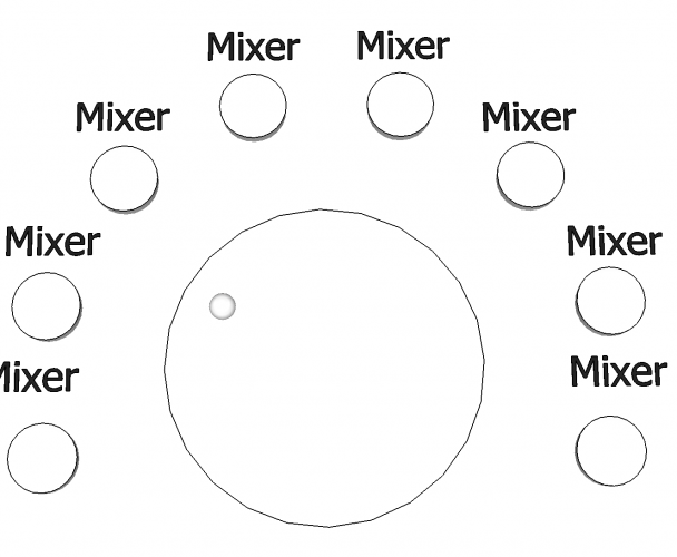
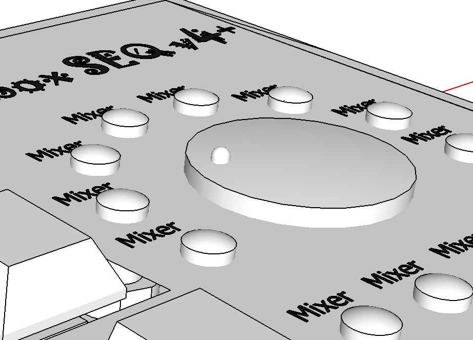
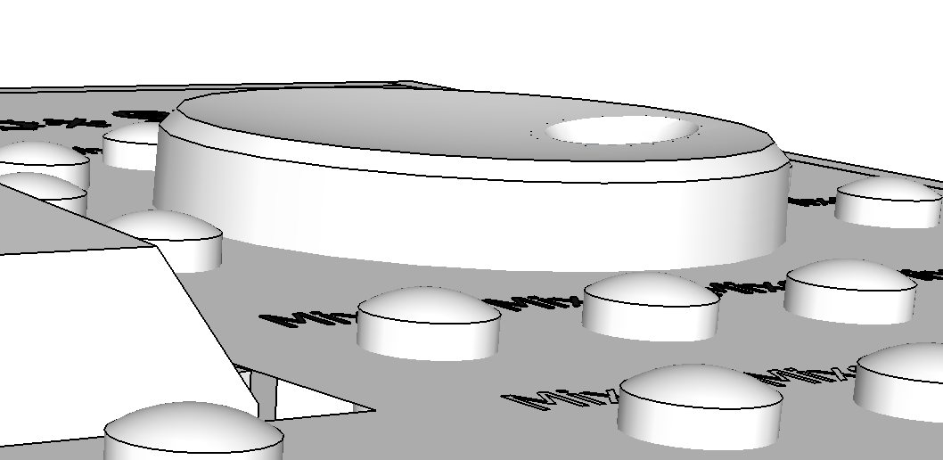
ALBS DK8,8-194 A.6/4,5 look pretty good.
also Drehknopf DK30-105 "Small Dial" A.6/4,5 schwarz could make a nice datawheel and solves the complaints of size/height a few pages back:


-
-
Just now, tago said:
Is it simply 1..16 on two top rows and bottom row + side panel like TK's graphic shows?
Yes.
Just now, tago said:I've another question about horizontal spacing between columns responding 1:1 to the display.
If i divide 148mm (active area)/8 is 18.5mm h-spacing. Is this correct? Nearest on veroboard would be 7*2,54mm = 17.78mm, the 12mm encoder knobs would have only 5-6mm space between them. That sounds and looks too narow to me. What h-spacing should be used?
I'm using 19mm spacing.
-
1
-
-
As explained above, the notch of the connector only matters when both PCB headers are keyed (allowing only one orientation). Considering putting the header on one end of the cable, the same pins are connected regardless of whether the notch on the IDC is "correctly" aligned with pin one (lower left as viewed from the top) or rotated about 180 degrees.
But in TK.'s example above, rotating the cable about 180 degrees at the display end will mean the backlight circuitry will be where the power rails are supposed to be and vise versa, and this is not good for the LCD in most cases.
-
Doesn't really matter. +5V draws off the USB power buss, so less pressure on the regulator. Most OLEDs use a charge pump for higher voltage anyway; there is no energy to be saved.
-
Verify each of the intended connection points on J15 are made correctly with the display.
Check for shorts between the cable pins (can happen with misaligned header)
You are fiddling with the contrast and brightness controls each time, right?What firmware is loaded on the Core?
-
Thanks for the positive feedback! Indeed, the limitation of this version is that it is 3U standard but sadly not Eurorack-mountable owing to the rails as @eptheca states.
Here's an interesting compromise though:
- The PCBs fit in a standard 3U panel, 85-86 HP width.
- Use 1U tiles ~40HP (i.e. 4U/7U case) to mount the displays above.
-
The CVs/gates/clocks/triggers etc. could easily fit below the PCBs with room for a MIDI socket or two.
- This wouldn't be too hard to interface and could even be hand-wired.
- Still necessary would be mounting points (brackets?) for the panel and Core/peripheral PCBs.
Personally I still think the power and space requirements of a full SEQ are suited to a desktop or 3U rack unit. But I can understand the wants and desires of self-containment and intermingling with the modular goodness. :)
-
Great! The structure already looks much flatter and quite useful for pattern changing.
Nice work from your side too.

-
1
-
-
All looks standard.
On an IDC header, pin 1 is on the bottom left when the notch is on the bottom. As the header is soldered to the rear of the display but PCBs are mostly designed from the front, the J15 Core header is mirrored to account for this.
-
As long as the LCD has a standard pinout, what you're doing looks correct. You should test another LCD.
-
A common problem with Eurorack power headers is they only work if the notches are polarised the same way on both the bussboard and the module. If the module has "pin 1" on the opposite side as the power output header and both headers are keyed, there is no way to correctly plug in the cable.
The Core schematic is correctly drawn as a "mirrored" header.
-
It's easy to fry LCDs, e.g. if you get the backlight circuit going full blast onto the logic pins, reverse the power connector or a data input etc. I'd try another LCD. Ensure the cables are connected; it can be confusing without polarised headers (always missing from LCDs). Don't trust the notch on the Core board, use the stripe of the cable to align the power or backlight.
-
NPN transistors don't source current very well. I'd suggest moving the diode in series with the resistor on the collector and tying the emitter to 0V. This way the current can be controlled with R1, otherwise it's not doing much. The capacitor you've shown in the Falstad sim won't do anything. R3 isn't necessary if you have the 220R in place. D1 will block reverse voltages but will also drop the gate voltage. Voltage < 0V will pass through. As long as the current is limited the 595 output will probably be okay with another output connected, even excluding D1. Diode clamps are better done in parallel with the node to protect, diodes connected e.g. to the power rails.
I'd suggest testing the circuit on a breadboard or perfboard/stripboard before ordering the PCBs.
-
Can you post the actual circuit diagram you're going off?

Displays not initializing after working for a while
in MIDIbox SEQ
Posted
Do your cables look like this:
Notice both connectors face the same direction relative to the cable.
On your one, one IDC is "up and the other "down"
TK.'s has a bend on the left connector.
I need a coffee, so not sure if this makes a difference electrically, but worth a try at this point.