-
Posts
2,524 -
Joined
-
Last visited
-
Days Won
149
Content Type
Profiles
Forums
Blogs
Gallery
Posts posted by latigid on
-
-
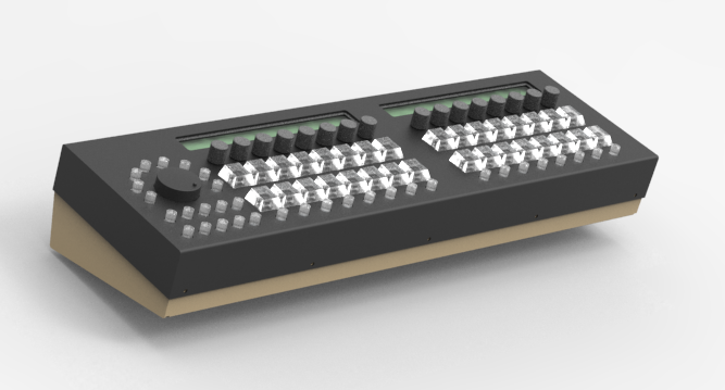
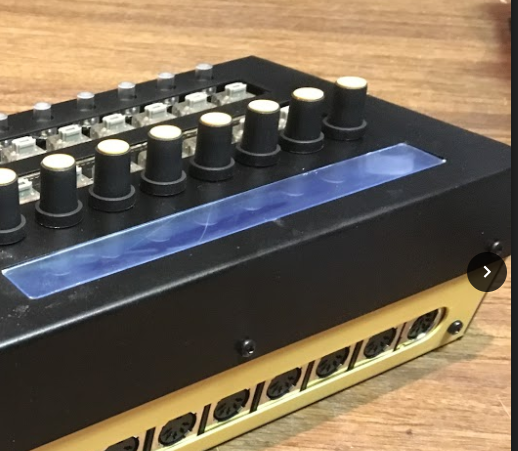
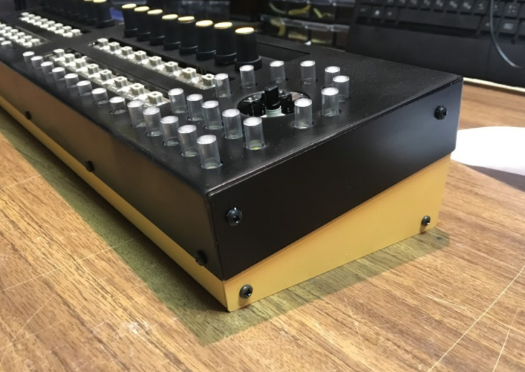
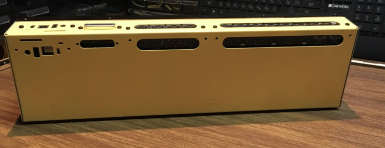
Adrian is finalising the case design, hopefully he doesn't mind me teasing a few pics. Note that these are not final and will probably change.

Concept, shown as the left-handed design. The PCBs will work both ways, but you have to choose a left- or right-handed front panel.
This one has too-high caps around the wheel. Originally the wheel PCB was mounted at a different height, but now everything mounts on a (very clever) interior shelf. Only one sort of round cap required.

Many things will change: circular holes for the MIDI DINs, different knob choice, maybe coloured windows.
The IO can be mounted either at the back or bottom. This means the unit can be either desktop or 19" mount :).
More info as I receive it.
-
 9
9
-
-
-
Sorry to see you go! It's good practise to put your location and prices for the items.
-
Thanks for reporting back, I'm glad you got it sorted.
-
As shown in the above image, the C+ pin is not connected to the switch and the other two terminals (left and right, between C+/B and R/G respectively). should be used. But try with jumpers directly on the pinheader too.
-
Testing inputs without DIN doesn't make sense IMO. You could add the SCS interface, but it doesn't help with your switch problem.
The random events are the SI transitioning HiZ-high (pull-up resistor attached). It will depend on where the clock pulse is as to the address.
Forget the switch and jumper one of the DINs (pins 3-10 to 0V. You should get the correct event.
Are you sure you have the pins of the switch correct? Best would be between NO1 (DIN) and C1 (0V). Between NC1 and NO1 will not show a difference. Between NC1 and C1 should give an event with inverted behaviour. Or is your switch different to that pictured (are individual RGB pins available?)
-
Or what's the switch model? Perhaps there's a diode or some weird pin arrangement blocking the switch action one way? Swap the DIN pins around?
-
Not sure sorry. The fact that the DOUT works indicates that the SRIO scan is okay. The high-to-low transition as measured at the DIN pin is correct.
Try another DIN?
-
Okay, then load up MBNG. That's what you'll want running for your controller anyway.
-
-
P.S. Please upload your images here so future travellers can benefit from them.
-
I'm not sure how MIDIO128 works in the default config. With _NG the SD card defines the hardware definitions, but the DINs should still register even without any (I think the shift register scan is implemented by default).
You can try
set debug onin MIOS Studio, this should give you feedback on any data sent or received by the Core.
-
Eh, I should read better...
Looks like there are already MOSFET drivers on the lamps. As they look biased to 25V, it seems that the 5V signal from a DOUT will not be high enough (did not check the transistor specs). But it could be tried with 5V supplied to the gate of TR7/TR8.
If you know what IC4 is, then the simplest way will be to match that voltage as driven from a DOUT. Please post the whole service manual if possible.
-
Looks like the lamps are already driven by some sort of line driver/level shifter. This is good, as one can lift the LEDs out and wire to DOUT that way. Considering the way they are connected, it seems like the 2981 chip will work better.
If "IC4" still works, another option would be to connect to its inputs. The driver chip looks quite strange; what is the part number on the IC?
Is the idea to use both the normal function of the mixer and something MIDIfied? Or is it a carcass just to build a controller?
-
In principle that sounds about right, but the current seems very high. Of course you have no resistor there, so the bulb will take what it can from the PSU. I think the 2981 can source only -500mA. If your requirements are bright lamps, then you should use relays or MOSFET transistors instead.
What sort of 12V lamps are we talking? If they're the small panel indicators, the 2981 will be fine. The other way around also works: ULN2803 provides eight sink drivers. You then power the bulbs at 12V and connect to the DOUT via suitable resistors. One drawback of the current boards is that there is no space for resistors onboard, so any current has to flow through the pinheader and typically thin ribbon cable wires.
-
I think it should fit in place of the resistor array, but please check the pinout. There's no header nor PCB trace for power; you have to solder something to the DIP socket. I recommend limiting the current after the 2981 with suitable resistors. It might be better to use the DOUT as-is and put together something on strip/veroboard with a 2981. What sort of current?
Also check here:
It depends on your particular revision of DOUT. I believe the latest ones require no trace cutting.
-
UDN2981 can even fit into the DOUT boards. They require a secondary voltage though (595 won"t run on 12V).
-
Well done! I hope the customisations worked okay. Let's see some build photos of the MBCV!
Best,
Andy -
I suggest to unzip all of the files here http://www.ucapps.de/mios/midibox_cv_v1_3.zip
into something easy like C:\CV\
you would then navigate as
cd C:\CV

make
perhaps you just have the asm in which case there is no command available. All of the subfolders (src etc.) are required to build a hex.
-
in MSYS
cd %PATH%is the command to change directories, where %PATH% is the location of your .asm
lslists the directories and files
cd can be run for one folder at a time, using ls to see what else is there
cd C: //opens C: driveor as a path
cd C:\2487\trunk\apps\controllers\midibox_ng_v1In your case, use cd until you are in the correct folder, then run make. If you have set up the dependencies and system variables correctly, your .asm will be used to build a .hex. If you haven't followed the other instructions to setup the system properly you get no file and a list of error messages.
-
Just now, graham said:
I can load the asm file in wordpad and edit and save it but which program do I need from those listed to create the Hex file from the ASM?
MSYS
-
Just now, graham said:
I thought it would be simple to convert an asm file to hex but it appears to be out of my depth.
Come now, don't be lazy! You're so close! Otherwise the MBCV will sit around wondering what it could have done with its life. -
Have you done everything written on the page? Come back when you have.
-
You could also try the following:
not sure if it's different for MIOS8.


MIDIbox SEQ new frontpanel idea
in MIDIbox SEQ
Posted
The SEQ uses new designs of Core/MIDI boards, so save those for other projects :)