

latigid on
-
Posts
2,524 -
Joined
-
Last visited
-
Days Won
149
Content Type
Profiles
Forums
Blogs
Gallery
Posts posted by latigid on
-
-
Did you define the max number of LCDs? I have some PCBs that provide more CS lines on simple headers if you need.
-
Here's one based on big beat with a lot of analogue Rhodes Chroma pads and FX, distorted Voyager + Sherman Filterbank. Dark at the beginning but quite uplifting later on. :).
-
I think "Nth" is what you want, but check the wiki.
-
Yep, you're right, I got my wires crossed.
The 3v vreg (+ diodes) will likely have trouble if the ambient temperature is high.
-
Enforce bootloader mode with the blue button held during startup, open MIOS Studio and set the LCD option and store.
-
Right, but as a test, why not try booting NG to see if it's something weird with KB or customisation?
Or are these rare problems with Mac MIDI drivers?
-
Lots of data being sent?
How about if you load the default NG program with no customisation?
-
Oscillators are not inherently unstable, but our hearing means we perceive pitch exponentially. So from one octave to the next means a doubling in frequency. If you want to control pitch on a VCO linearly (commonly 1 volt per octave), then you need an exponential converter for your keyboard or MIDI data. Most of these circuits have a temperature coefficient that is always present.
Digital oscillators just count a number of divisions of the master clock. Quartz resonates at a very specific frequency, and so it's much easier to count pulses this way. I think the SID uses a lookup table to derive the oscillator frequency.
-
A bit of drum'n'bass and goes into some more ambient house stuff. The bass on the Rhodes is a bit "flabby" but there you go.
-
 1
1
-
-
IIRC the CPU monitor is in the SEQ itself through one of the menus.
-
If using the STM32F4 Core, you can remove the jumper for USB power and just plug into the 0.1" header.
The 80% CPU usage seems high. I still wonder about the 3V supply.
-
Are the LCDs powered by 3V or 5V? How hot is it where you are? Without much more info, the problem could come down to the DISCO board voltage regulator overheating. Is the USB cable okay? Maybe the connection doesn't make good contact somehow.
-
What kind of PSU are you using? Does it supply enough current? Can you measure (or better 'scope) the power rails?
Photos of the connectors could help.
-

LEDs are nice and bright; this is from the rear side! I'll need some help/fiddling with the switch portion as this is not a 1:1 BLM.
I noticed a similar concept from 40%club:
http://www.40percent.club/2017/06/alps-48-rgb.htmlI considered mounting 5050 LEDs in this way last year, but IMO the available ones are not really bright enough. As well, I'm not sure how reliable a "bridge-soldered" LED would be in the long run after a lot of keypresses.

-
It should work, although I'm not sure of the advantage over my concept with illuminated Matias switches. Don't take it as discouragement; this is MIDIbox and you are free to design your own hardware as the original spirit intends.
Best of luck,
Andy -
A little while ago I found my collection of mp3s I made with my band about 10 years ago. Everything is LoFi with distortion and dropouts as the jams were recorded onto a dynamic mic and then cassette tape, then transferred to the computer. No processing in post, mistakes not fixed, no song titles, just the code of the tape and a few descriptors. The mixes are often off, and these were just recorded as they come, so can be quite long-winded. But I still find them quite cool.
Synths/keys used are Moog Voyager, Rhodes '73, Rhodes Chroma, a couple with MS-20. Sherman Filterbank, RE-150 Space Echo and Moogerfooger effects. I play bass on a couple.
You'll probably like the "jungle" drum and bass drums (all live), and there's some vocals too. The singer probably prefers that his levels are low :).
Can't be bothered with Soundcloud/youtube at the moment, so I'll post links to dropbox.
https://www.dropbox.com/s/gtfo0yzb86lr7wq/65A%20distorted%20fedback%20db.mp3?dl=0
I think the delay used here is a Boss DM-300, a 4096 cell BBD. The input is overdriving which gives some very crunchy sounds on the Rhodes.If anyone likes, I can post the longer ones which go up to +20 minutes continuous. Mostly it's dub/drum'n'bass style but there are some different ones too.
Best,
Andy -
For those playing at home, there's a delay on Matias switches, apparently as they are producing a newer design with "reduced key wobble." I didn't think the wobble was too bad, but there you go. The restock is due at the end of August. In the meantime I will try to test things without switches and also look at an order of keycaps.
-
Nice! Analogue detuning from the Dom ?

-
Should be okay. With a matrix design, you usually get entire rows or columns out rather than a few here and there.
One thing I've noticed, is that the through hole plating is not always the best. For LEDs and switches that don't work, try soldering on both sides of the joint, adding flux if you need to. You have to be careful of melting any plastic components, and also e.g. soldering LED legs one at a time so the alignment stays good.
-
Ah, it's the MB-6582 one I suppose. Can help there then.
-
Is it the one for the Quad I2C MIDI? The pin arrangement is special, having "3-2-3" rather than the much more common "1-4-3".
I can have a look in the parts drawers.
Best,
Andy -
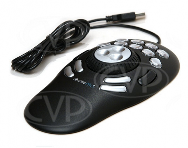
Looks like a nice wheel!
Compare with the DK-38:
http://www.albs.de/ecom/images/866004.pdf
The RS one is just 1mm shorter in total height, so I'm not sure if that would make too big a difference.
-
2 hours ago, jarvis said:
My main concern with the design is that, at least according to the renderings, the data wheel is not flush with the surface of the case.
The idea uses a DK-38 knob from ALBS, and I've asked Adrian to accommodate for it by cutting a hole in the front panel. So it will already be sunken down a bit. But no, it's not flush with the panel. They also have a fairly long stem, which is why the wheel on the Wilba version is "panel mounted" to the PCB.
Do you know of a datawheel knob that sits lower? Please tell me a part number and I'll have a look.
2 hours ago, jarvis said:I would expect this to lead to accidental knob nudges when pressing the frequently used function buttons surrounding it,
The suggested encoders are 24ppr/24 detent, so you'd need to turn the knob 15 degrees to register a click (or is it half that with the fast encoder scanning?). Doing a bit of maths says you'd have to turn the outside (least torque required) almost 5mm.
2 hours ago, jarvis said:or at least make some of the ergonomics a little odd since you have to angle your finger around the edge of the data wheel.
Unless you have tiny Trump hands, you should have more than enough room to reach all of the buttons without bumping into the encoder. The usage is not 100% clear, but it's possible that the wheel and buttons will be used together quite frequently.
2 hours ago, jarvis said:Is there other hardware you've modeled this layout after?
It's mostly original and aims to use the remaining space left over from the LCDs/OLEDs. But perhaps something like this:
-
Hi,
We might have to move the discussion soon, but what the hey.

Yes, the Waveshare boards look good and are much smaller than the Discos. There are some others which have an even better arrangement (mounting holes and top-mounted header pins), but on the face of it Waveshare look a bit more trustworthy. Still have to find time to test!
The downside is exactly that: no STLINK onboard. It could be possible to flash on UART0 (I think), but you still need a USB-UART converter.
I bought something like the following:
but if you have a Disco board it should also work to connect using the normally jumpered header pins on the ST-link side.
The USB module optimally aligns close to the Core on a 5 pin header, but it could be placed further away if needed. A main reason for moving to another carrier is that the USB MCU pins are on the header, so no more flaky microUSB! The host/slave switch is probably not proper USB spec, but should be okay for DIY purposes. The SD card sits on another PCB underneath (J16E), with the LEDs and reset button. Hopefully that's okay given the lack of power switch. I didn't put one in because it would've complicated the USB spec (should apply power prior to data pins).

OLED displays
in MIDIbox SEQ
Posted
Sounds right!