

latigid on
-
Posts
2,524 -
Joined
-
Last visited
-
Days Won
149
Content Type
Profiles
Forums
Blogs
Gallery
Posts posted by latigid on
-
-
Mutable has changed their forum, I'll see what I can do.
Offsite doku = bad!
-
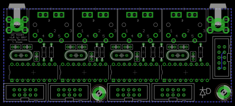
Perhaps a few teaser pics:

Closeup of the wCore, note the USB/SD "modules" above:
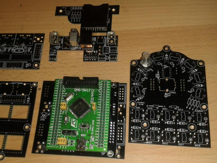
One tricky thing was to mount an LED but not go beyond 160mm x dimension.
This was the answer:
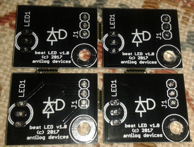
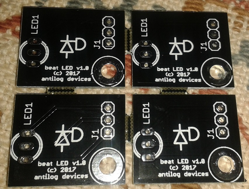
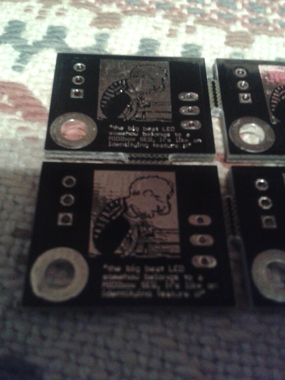
There was room on the back, so this is dedicated to the guy who loves the Beat LED:

A bit hard to capture the mask text, but it reads:
"the big beat LED somehow belongs to a MIDIbox SEQ, it's like a defining feature :D"
-
 3
3
-
-
The best thing is you can choose the keys you want:
The options like you say are click, quiet click or linear. I though I'd like the linear, but actually I prefer the quiet click. Some people enjoy clicky keys, so no worries there!
PCBs are here, unfortunately they didn't do the cutouts for the LEDs, so there will be a delay in testing.
I also need to get some parts orders done -- getting there slowly!
-
It's okay, I'm not offended. It's just unclear from your wording whether you were suggesting "You may want tio take a look at some of the matrix keyboard..." in a general sense or for this project. A few weeks ago you were asking for extra headers to use panel-mounted switches, so my initial sense was for the latter.
Fact is they _are_ really cool hardware items, and they should definitely be incorporated into more projects. You might have seen Wilba's Cherry Jammer keyboard with a clever velocity sensing mechanism, or I think it's antichambre who was looking at reflectometric light sensors.
No DHL today, so another few days to wait at least. :(
-
It's true that some of these layouts could be useful for other projects; I suppose they're somewhat related.
It's also a different story doing "bespoke" builds rather than a repeatable project. For instance, the closer spacing means the caps must be cut down (or those custom clear caps, which don't look great IMO), and not everyone is prepared with the right tools.
Another thing to consider is how the button layouts work with other hardware. 19mm standard spacing is actually perfect for a 40x2 LCD.
Sorry, I'm not trying to be too grumpy. The PCBs were designed over a period of months with the whole build in mind, and the order was placed weeks ago, so it's not changing unless there's a problem with the prototypes

-
It's not that GW, the I2C address is done on the PCB, so the PICs respond to the datastream depending on the states of two pins.
-
Of course, easy mode would be to use an existing PCB and MX-type switches. But those keyboards are built for a specific purpose, as are mine. What will you do with the extra four columns and two rows? Arduino-compatible, but using an SPI-controlled matrix driver. SRIO on a MIDIbox simply updates with the clock tick and requires almost no overhead. (Plus, the former doesn't fit with TK.'s plans of derivative HW that's simple to integrate.) Are the LEDs addressable or always on?
The biggest challenge is to get LEDs to illuminate the entire switch. Hopefully the PCBs come tomorrow so it will become clearer to explain, and I'll probably start a new thread for it.
MX-type have the LED as THT close to the key, or an aperture on the north edge. This is okay if you have a small glyph to illuminate, but for blank keys it looks bad. Enter Matias, where the entire key is transparent. But there's no room for LEDs, except on the underside as reverse mount. Now try to find a bicolour LED that's bright enough. I did some testing with 2x lensed 1206-ish sized parts. Maybe it could have worked, but it would've required 4 LEDs per switch. This increases the price and still isn't perfect.
Here it is. It's not the intended use for these LEDs, but it works well. You can choose R, G or B, but the BLMs support only two of the colours. You could control the third separately, or all three with a different driver.
This is the route I'm gonna take, you're of course welcome to try your own methods with existing hardware.
Best,
Andy -
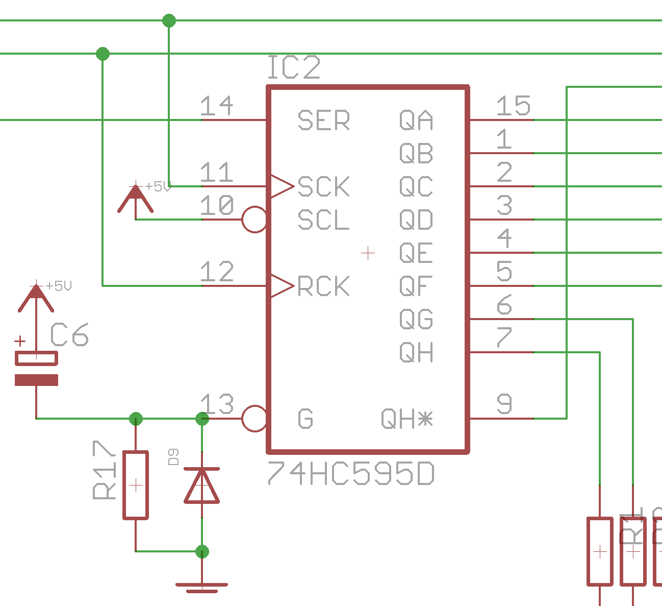
I don't think it will work. The display normally initialises on start up. Switching with the power running will likely lead to garbled display pixels. You're also messing with the integrity of the datalines. DIN/DOUT might work, but you'd be sending the data right before switching = corruption.
A bit laborious, but you could send the data lines of J8/9 and the displays to additional buffer chips (541 or 125). (It would almost work with the buffers/595s already present, but there are extra signals to deal with.) The outputs of the buffers can be enabled by tying the /OE pins low. Meaning if they're high, no signal passes. You then switch one datastream off and the other on, probably with a short manual delay in between. Resetting the Core would also not hurt, but could be okay without.
-
3 minutes ago, FantomXR said:
Hi!
Thanks for your reply!
I think using a RC delay sounds like the simplest solution. But why should I set this pin to high?
And do you have any idea what kind of values to choose?
thanks,
Chris
Hi,
/OE means output enable, active low (/ or a line on top of the pin name). When it's low, outputs are enabled. When it's high, outputs are tristated/high impedance/open circuit. Notice the DOUT pin 13 is normally connected to 0V/ground. For this to work, you have to charge a capacitor (e.g. 10uF) from +5V to /OE, then provide a resistance to 0V (10k, you choose the delay though). When the power is applied the /OE pin will "see" this as a high logic level, then fall to the low state once the capacitor has charged.
Finally, you add a diode to discharge quickly once the power turns off. Anode side to 0V, cathode side to /OE.
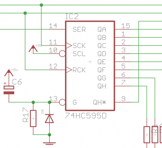
You can distribute this circuit to many /OE pins; I did the BLM 16x16 in groups of 4.
Best regards,
Andy -
The state of outputs on 595 shift registers is undefined on power up. But it's possible to temporarily set the /OE pins (#13) high with an RC delay, meanwhile the Core will have sent a "clear all outputs" signal to the 595s. You could potentially do this with a free MCU pin too. Keep in mind that the /OE pin will be high impedance, which means any transistor bases used as current sinks will be floating = not a good idea. To avoid this, add a pull down resistor of 100k or so to the transistor base.
-
Interesting. What are we listening to exactly?
-
Hi Jack,
I have to think about that, but for the moment you can follow the connections on the schematic:
http://www.ucapps.de/mbhp/mbhp_blm_map.pdf
I'm here and I will help you. Please use the build thread or PM with specific problems and we'll get to the bottom of it.Best,
Andy -
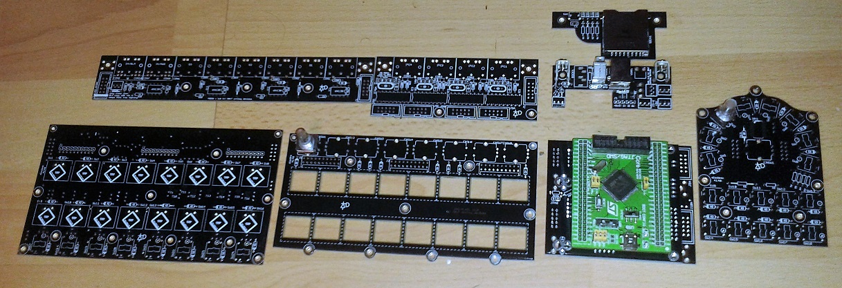
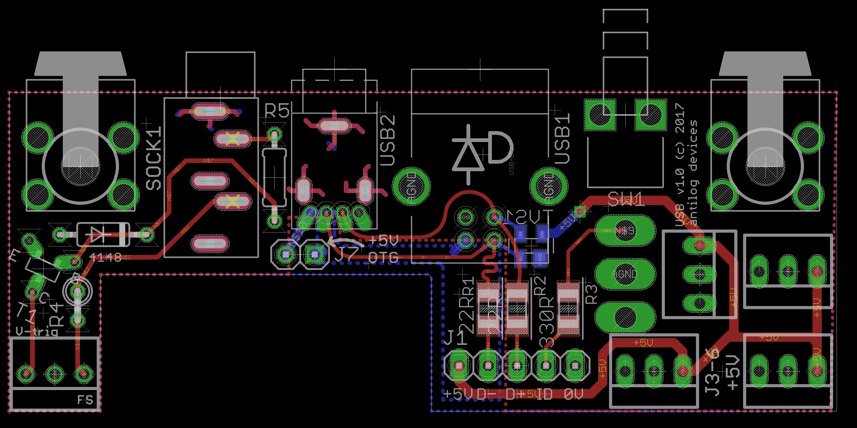
This last order had 11 different PCBs in it and includes everything needed for a SEQ, like the MIDIO/I2C/line transmitter and also a new design for a Core that doesn't rely on the Discovery board. The USB entry module had some fab issues, because it's not clear how to call out plated slots:

(the thing to do is to give the actual cutout of 0.8mm min. width in a separate file, not just the router path as I've seen before)
But hopefully they'll be on the way soon.
The subsequent steps will be to build and test to make sure it's all sound, then send a set to AdrianH, so he can work on the case once all of the heights/dimensions are known. Of equal importance is to get TK. on board, as this is three different BLMs that will need updated programming and HW config files. He is extremely busy this year but if the past is an indication, he will give a bit of his "vacation" to the project. Otherwise I'll take the train to Munich and sleep on his doorstep :P.
Hopefully things become clearer in the next month or so. If all is well I can start to take orders, although I may have to look further as the forum is quite quiet at the moment.
@gerald.wert
No problem! I spend the time on these projects when I can because I want something nice for myself, and I also want to do good by those who want to take part. But this is MIDIbox, and if you have the time and motivation, everything is there to build your own custom unit.Best regards,
Andy -
@borfo
I've already ordered the boards a few weeks ago, so this is a bit moot. But I've had some thoughts throughout the day.IMO, there's not much point in breaking out the matrix further for individual button wiring. Like you say you could design something to work with or replace a DIOMATRIX, but you'll still find work needs to be done on the switch side. Instead you might find it's easier to use DIN/DOUT modules instead and forget the matrices.
One of the goals of this design was to use high-quality switches. The Matias ones are rated for 50M key presses; I don't think you could say the same for the Chinese ones. The latter are only single colour, so the improved features wouldn't be implementable. It's a huge pain to find illuminated switches at reasonable cost, and I've put a lot of time into finding a solution. Matias switches cost 0.25 USD or less, you do need a custom keycap but their price will depend on the quantity. Should be around $1 each for switch + cap = $32 per SEQ. IMO that's not a bad price and the HW should be commensurate with the amazing software TK. provides.
@gerald.wert
Personally I wouldn't trust those switches, and you'll find even bi-colour switches are very hard to source let alone RGB. You might fit some kind of SEQ in a C64 case, just keep in mind the LCDs need around 360-70mm, and you probably want some kind of datawheel. -
Great, but maybe you can be more specific? I can't see how your +5V connection was missing, apart from cold solder joints, but you said above that the soldering was fine.
-
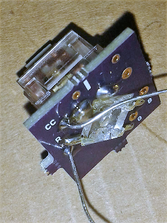
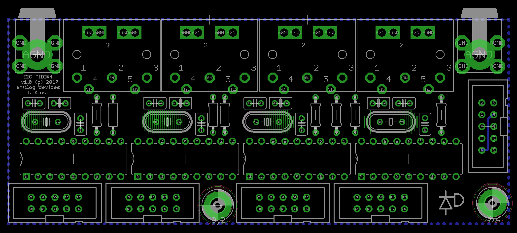
Have you already cut out the rear panel? If you're interested, I have a board at the fab at the moment:
It's 107.5mm across with 21mm spacing between the DIN5s.
Still needs to be tested, but the alternative is there.
Best,
Andy -
J2_SI is only required if you connect some sort of DIN chain to your Line sender, and you need to get those data back to the Core. But it doesn't matter if it's soldered in place for your case. If you look on the uCapps page you can see the situations where the configs are explained.
Good luck!
-
You assign a whole SR to 8 gates (or clocks/triggers etc.), so the two from your AOUT modules will be replicated.
CV_GATE_SR1 3is what you want, assuming the line driver is connected to J2 of the Wilba PCB.
-
Good that it's working. What was the exact issue for the benefit of future travellers? Backwards RNs?
-
... diodes could be backwards or missing...
-
The ones you linked are the correct type, as long as Reichelt delivered the correct ones.
There are two (well three, but dual terminator is not so common I think) types of RN, one where the pins are isolated into individual elements, the other has one common/bussed connection and are used for pull-up/down resistors.
A picture = 1000 words. It can save a lot of time for those helping you troubleshoot to check if your soldering is sloppy, maybe the switches you used can be installed sideways etc. etc.
-
The question of course is whether you also used isolated networks for the CS as well as the Core?
-
-
For completion's sake, did you get the ST7066U LCD working?
Btw, these threads aren't a waste of time, as there's a lot of good troubleshooting tips. Could be a useful entry for the wiki?


MIDIble of the week: Ambika + MBNG synth by ilmenator
in MIDIbox of the Week
Posted
The post in question is here:
http://mutable-instruments-archive.net/forum/discussion/8485/tsfkaa-pro
I could download the images and put them here, but I'll leave it up to @ilmenator if he wants to do it.