

latigid on
-
Posts
2,524 -
Joined
-
Last visited
-
Days Won
149
Content Type
Profiles
Forums
Blogs
Gallery
Posts posted by latigid on
-
-
Waitlist:
taximan (PCB+Case)
-
Did you try to configure the port as AOUTX as opposed to a MIDI or USB channel?
-
Thanks, I added it.
-
The long slider shafts are ok for me. LEDs are too bright (especially the white ones) with a 220 Ohm resistor, I will probably replace it by a 1k resistor. Silicone covers would be nice.
Notice I recommend 10k for the LED resistors, hopefully you can change them. For the covers, perhaps some sort of silicone block or tube could be used, I had a look at the hardware store this week but didn't find anything. Or unmelted hotmelt glue sticks?
They are good, but I've only 4 spacers, a spacer for each screw would be better to avoid that the PCB is bended during mounting
I don't quite understand; only two circular "washers" should be needed (right-most top and bottom viewing from the PCB front) as the remaining PCB area is covered by the spacer?
-
Great work! Which company made it? Did you do the infill yourself?
-
Okay, thanks for the file, let's see how yours goes and I can add it to the OP. I didn't have issues with mine (corners are properly rounded) and I think TK.s was also good? In any case, the spacer holes are a few mm larger than the buttons.
-
So I should be able just to use the out on the Midi i/o correct? so J11->midi I0-> Quad IIC BLM connector
Yes, it should work from J11E. Or if you connect a MIDI IO board, you could for instance take MIDI IO4 from J2.
-
Thanks for the kind words! It's very satisfying to see everything come together after countless hours of design, component sourcing and dealing with many different companies.
-
Here some amphetamine for those who haven't built their case yet! :-)
Note that I added some enhancements & fixes to the MBSEQ firmware while working on this demo (demos are always a good possibility for me to doublecheck that everything is working as expected!). The changes are already in the SVN repository and will be released soon.
Best Regards, Thorsten.
TK.: very nice! It looks like the slider implementation is very good. I guess you kept the longer sliders in? This will be a personal preference I suppose. An idea I had was to make or buy some silicone covers to use as slider caps. This might make them a bit more ergonomic and also act as diffusers for the LEDs which can be quite bright.
I take it that there's no issues with the case? Stability (i.e. no PCB flex) is good with the extra standoffs? Are all M2 grub screws installed? Do the bottom feet work?
Next up will be to connect up extra expression pedals, CV inputs etc. :) (another DIN connector?)
So just to confirm: quad IIC blm port connects to J5B on the STM32F4 core?
The BLM/quad IIC schematic always gives me a headache :). My approach was to harvest old PC cables (with single or dual female pin sockets, could also crimp new ones) that connected all of the front switches, LEDs etc. to the motherboard, and join them with an IDC10. I'm still using the F1 Core, but luckily I have a breakout board which also separates MIDI IO 3.
If you have an older Core8 you can always swap out this for the miniCore during testing, just use temporary clips on the MIDI outs. You need to supply power to the BLM, and please don't send data without the main board powered up.
-
Hmm,
I still think there's some merit in this, for example with a single PCB and 4 displays (e.g. MBCV) you could get away with 4 standoffs and simpler wiring/less POR circuitry etc.
Did you consider FPC/FFC sockets? A quick search revealed that all of these are SMT but the metal pins are more amenable to solder than the flat cable. 0.5mm pitch correct? Tricky but doable.
-
The correct side is the rear, otherwise you will also need to mirror the cable or its connector. You may find the easiest way to remove it is to cut or slide off the plastic part of the header, then remove the pins one by one. (Technically you could also melt the solder and push the pins through, but the result will probably be quite messy.)
-
Keep in mind there are two main types of LEDs: older yellow, green and yellowy-green which each have a forward voltage of about 2V and newer diodes (especially green at 525nm, blue, white etc.) with Vf= to 3-4V. Check the data sheet and compare both the forward voltages and brightnesses in mcd. Brightness is somewhat non-linear with respect to the current passing through the junction but it can be tuned somewhat.
-
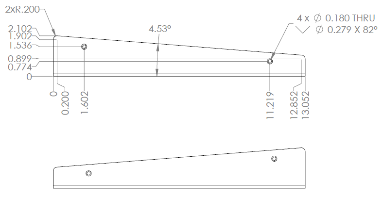
Okay, please check the build guide thread for drawings and graphics files of the side.
-
Here are a few images of the side in case you want to make wooden end cheeks. Dimensions are in inches, please check them against your case to be sure.

EDIT: suppose you could make some metal flange rack ears too! Oh, these screw threads are 6-32 and all screws are stainless steel so the aluminium parts should last for a very long time.
-
I don't have my unit here to test, it's at a friends awaiting a few modifications (my case had fewer standoffs so needs mechanical strengthening). TK. should be able to give you an idea of current draw with all LEDs lit, probably he has a nice bench supply running :).
Perhaps a small caution to check the board for errors before starting. They have been electrically tested but there's a remote possibility of unmasked ground plane which could give a short if covered with a lot of solder. I have a few spares here which I will go over carefully when the light is better, will let you know if I find anything.
-
Glad you're enjoying the cases! I was equally impressed with the quality and maybe it's a road to go down for later MIDIbox enclosures.
They had to do a few minor modifications during production, so I'll just get an update and provide the side dimensions for chunky wooden add-ons :).
-
For the older 32 bit Cores, yes you can chain an ETH and SD off the same cable because they are pinned to accept different RC lines if I recall properly. For the F4 Core, you have SD on board, so why the need for another?
-
Cases have shipped, please let me know if there are any problems (e.g. defects etc.) as soon as possible.
-
Okay, well I'm on holiday at the moment, so I won't be able to remote debug very easily. Even with a short on this resistor it would only kill that particular section and not the whole 5V line.
5V short could be anywhere on the board, not necessarily at that IC. Check the vias and mounting holes too.
Bonne chance!
-
Interesting approach, what is the intermediate board between the Core and IDC6 connectors?
-
Thanks for the tip, originally I had 5 extra RNs in.
For the transistor/resistor pairs, what short do you mean? Short to ground? You might have to upload photos. Note that the bottom right transistor pin should be connected to ground. All 74HC165 inputs have a pullup to 5V. Please check carefully around this pin, is the solder mask scratched? If you try to reflow the solder it can help.
-
Good news is that these WS2812B 5050 LEDs will probably fit (just!) underneath the clear shaft encoders I have, everything on the top PCB layer. No cutouts will also make the PCB routing easier, this was a challenge with the BLM.
One caveat that I read about these is that the sample clock must be very accurate (to within 150 ns). Seems like the F4 should handle this though?
Now to look for a transparent tact switch :)
-
A new BLM has Been Bugged!

have got a short beetwen 0v and 5V...
Can happen. Start with the R1 bridge, you may have a small short if you scratched some soldermask off. Check every cap/ pins for 5V and pin 16 of the 10k resistor networks.
-
Interesting solution! But we have to consider how the illumination will work with the hardware too. There's one option using a clear shaft encoder but it only has a 4mm hole. Maybe through hole addressable LEDs bent over a PCB hole could do.
Alternative to LED encoder rings: illuminated red-green encoders?
in Design Concepts
Posted
Okay, I have the encoders and a 5050 WS2812 LED to test. The problems is that the LED is around 1.65mm tall but the clearance underneath the encoder is only ~1.1mm.
There are a few ways around this. First, you could solder the encoder in "proud" i.e. raised up above the LED. The neatest way would be to rest the PCB flat against a work surface, insert the encoder and solder from the top. There's a slight risk that your encoder doesn't go in straight.
Second is to use a washer as a spacer. Nylon is best for non-conductivity. Trouble is there are no washers of the right size. M5 is good on the outside (10mm) but too narrow inside (~5.5mm). M6 is just too small inside, M7 doesn't exist and M8 is far too wide on the outside. We need a washer with 7.5-8mm ID and 10-11mm OD. 2mm thick is best, but 2*1mm would also work. I tried to drill some M5 washers to 7.5mm but the bit chewed up the plastic. I also looked at imperial sizes, 5/16" is fine but 1/2" OD is too much.
An O-ring would at least be thin enough but to get the right height you need 2mm cross section/thickness (stacking them would be difficult). So then we have 7.5mm ID and 11.5mm OD which might just work. I also worry about the lifetime of rubber products.
Lastly one could get pieces of 2mm acrylic laser cut; they could even be square to save on machine time. I wonder about the expense of this though.
So, that's where I'm at at the moment, if you have any ideas please feel free to share.