

latigid on
-
Posts
2,524 -
Joined
-
Last visited
-
Days Won
149
Content Type
Profiles
Forums
Blogs
Gallery
Posts posted by latigid on
-
-
I see we are coming from different points of view: menu-based vs. knob-per-function. I know that I prefer the latter approach, for instance the sammichFM is a great compact synth but editing parameters on a 2x20 LCD and one encoder is quite unergonomic for me. I can see how having only depth controls makes panel labelling easier, but I prefer full access using the encoders (albeit requiring ninja skills to learn where each parameter is positioned). Selecting each channel one at a time and the configuration of its LFOs, ENVs, SEQ (also amounts from MIDI data such as velocity, AT, CC) etc. is also my preferred workflow.
For example, I would see that Channel 5 is active from its illuminated button, so I would know the encoder banks adjust the modulators' depths for this Channel. To change parameters for ENV5B (using my nomenclature) I press the left hand buttons "B+2" which shifts the encoder bank to ENV control. LFO5A = "B+3." These could be indicated with multicolour LEDs e.g. Channel Selected = green, "Bank" Selected (in my concept one of CONFIG, ENV, LFO etc.) = blue, and if the Channel and Bank numbers happen to match you will get cyan.
So you do have some multipurpose buttons, but thinking on the idea for a while this is the best "full control" solution IMO.
I think that at the end we might be able to use the same frontpanel, but labels need to be customized based on personal preferences.
I agree, there could be one PCB/PCB set with different faceplates depending on your preference :). Buttons/encoders could also be left out for instance if you didn't want a dedicated tuning control.
-
I fear that I've to create an alternative frontpanel design for my own usecase... :-/
If we can agree on the hardware there's no reason why two different front panels couldn't be created. My approach places editable parameters for each modulator on its own encoder bank, on a per channel basis. It also needs a paging key for a second set of controls on the 4x4 encoders. Note your proposed encoder assignments do not include rate controls for the LFOs, A/D/S/R for the envelopes etc. -- how would you adjust these parameters? -
Don't know what happened, so I'll put the pictures back in here:


-
 1
1
-
-
Please note: LFOA, LFOB, ENVA, ENVB, MODA..D are actually called LFO1, LFO2, ENV1, ENV2, MOD1..4, please change the graphics accordingly to avoid confusion.
I think it will be simpler to identify modulators this way. I.e. Channel 1 LFOA = LFO1A, Channel 5 MOD C = MOD5C. Then the MOD is easy to assign across Channels.
From my point of view, the encoder assignments are too much channel-related.
Can you explain what you mean by this? I'm thinking about the following structure hierarchy, sorry if the pictures weren't clear:
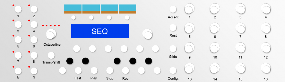
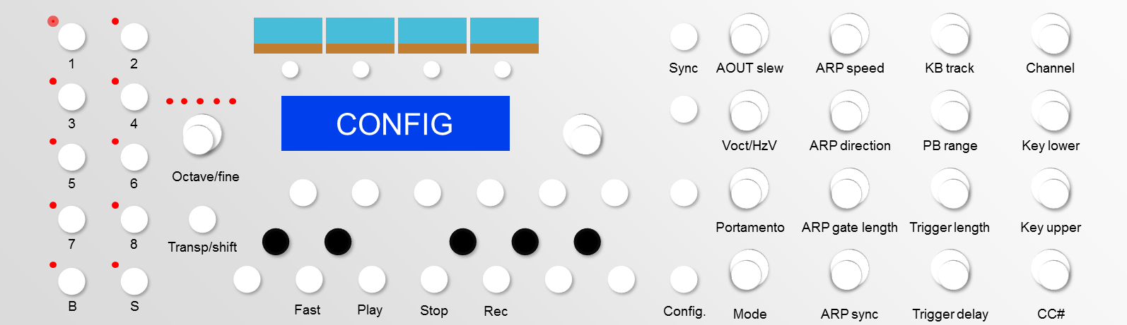
Choose a channel. Here on one page you can adjust all 8 modulators, activate the sequencer and apply velocity/aftertouch.
Click "Config" and you have a second page of options.
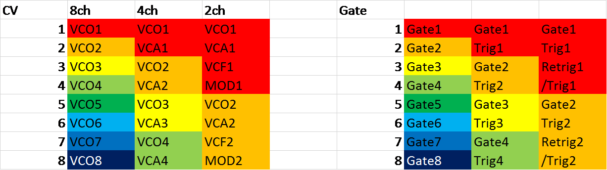
Bank+channel number will select each ENV, LFO, MOD and SEQ, some have two pages switched by Config such as the 16 steps of ENV2/B and SEQ. To me this is the most intuitive way to access all parameters of a modulator.I would prefer the configuration 2(VCO, VCA, VCF, MOD; Gate, Trig, Retrig, /Trig) with encoder assignments which change the most important parameters of an "instrument", such as
I think a more flexible approach would allow 2, 4 or 8 voices. Especially in a modular setup the concept of 8 CVs is very powerful, going beyond just a MIDI to CV converter.
And the default encoder assignments could be:
ENC1: CV1 Octave
ENC2: CV1 Semitone
ENC3: CV1 Finetune
ENC4: CV1 Portamento
ENC5: CV2 LFO1 Depth
ENC6: CV2 LFO2 Depth
ENC7: CV2 ENV1 Depth
ENC8: CV2 ENV2 Depth
ENC9: CV3 LFO1 Depth
ENC10: CV3 LFO2 Depth
ENC11: CV3 ENV1 Depth
ENC12: CV3 ENV2 Depth
ENC13: CV3 Value (Changes Octave/Semitone/Finetune)
ENC14: CV4 Value (Changes Octave/Semitone/Finetune)
ENC15: CV4 MOD1 Depth
ENC16: CV4 MOD2 DepthENC1-3: not required as there is a dedicated octave/fine encoder + a chromatic keyboard for semitone transpose
ENC5-16: for the most flexibility I suggest all modulators of a channel are accessible on one "bank"
Same for the ARP and SEQ configuration.
Is it not better to have all 16 steps on their own encoders?
-
Im sure you guys have already thought about this...... But, will this design be eurorack friendly? i.e. Fit in a 3U rack?
I'm aiming for 3U, although I don't have definite PCB dimensions yet. Not quite sure if it will go between a pair of rails. The next question is: should it? The older idea with lots of LED rings consumes about 700mA if I remember correctly. And it would be around a whole block of 86 HP. But the IO is flexible. Either you can use the line drivers and connect up a breakout panel in the rack or else put your jacks/bananas/whatever on the box itself. As I've mentioned before my plan is to enclose a SEQ and CV in some sort of 19" case with a breakout panel and a decent PSU.
-
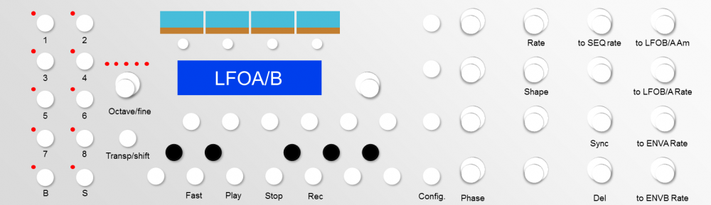
Okay, I've thought about a new MBCV v2 implementation after a chat with TK. and some time on my train journeys. I've followed the Lemur templates and here is what I've come up with. We don't have a panel or PCB yet so all assignments are flexible! But as I imagine multiple pages I've tried to group similar functions.


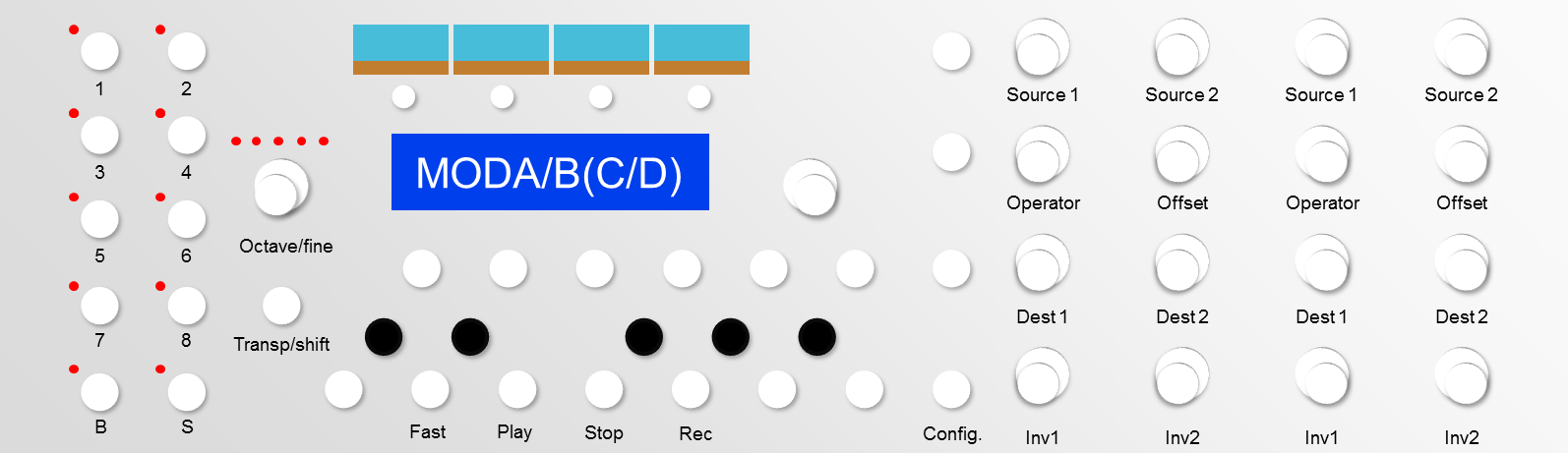
Here with channel 1 selected, the encoders adjust the amount of each modulator applied to it. Bipolar control could be quite interesting!


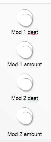
The right hand column of encoders is kind of a "meta mod." Instead of these fixed assignments (as currently in the Lemur concept) two modulators could be applied for each of of LFOA/LFOB/ENVA/ENVB and sent to any destination on the MBCV. This is a bit redundant considering the actual MOD section, but could free MOD up for interesting combinations, also for AIN control. Easier to label this way!


+ destination?
The aim would be to build a new control surface for MBCV without LED rings but using illuminated encoders as supported by TK. This way the PCB routing is simpler with less DOUT pins and less space/holes are required on the panel.
The layout has:
- Left hand buttons for selecting CV channel, and choosing the section (CONFIG, LFO, ENV, MOD, SEQ). I discussed with Thorsten about different "banks" and "scenes" although I'm not yet sure how these are implemented. Would a scene be like a preset of CV assignments?
- 4x OLEDs for scopes
- SCS (standard control surface of LCD, encoder and 6 buttons)
- Dedicated octave/fine tuning
- Chromatic keyboard layout for transpose and SEQ programming, with some dual purpose buttons
- Bank of 4x4 encoders which change parameters depending on which modulator is selected
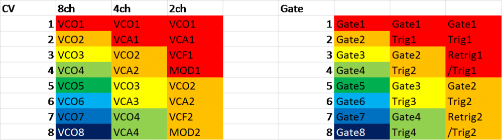
As far as I can tell there are two possible uses of MBCV, either as a MIDI to CV converter or as a crazy LFO/ENV/SEQ source for a modular synth. Here are some possible architectures:
- 8 channel mono: 8(VCO; Gate), so 8 monophonic synths. Probably the best option as a modulation box. Could also operate as 8 voices on one channel, but I think few synths would use this
- 4 channel: 4(VCO, VCA; Gate, Trig). This could be controlled over 4 separate channels or 1 channel of 4 voices. (Trig is a short pulse sent at note on.)
- 2 channel: 2(VCO, VCA, VCF, MOD; Gate, Trig, Retrig, /Trig). Again two separate monophonic channels or one duophonic. (Retrig is a second pulse sent after a fixed delay time or using another threshold such as aftertouch or a modulator. /Trig sends a pulse when a note is released.)
Anyway, those are my thoughts without too much consideration into what's possible on the programming side :). Please feel free to add ideas or critique.
-
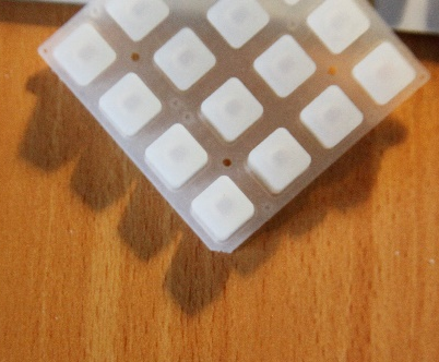
i solder the green ones... more than 7 hours.... Thorsten you're definitely a god! :D
go to the blue...
Andy, some bicolor led in smd package could work in this design? it could save buck and time.
something like this:
http://www.mouser.com/ds/2/239/S_110_LTST-C155KGJRKT-587277.pdfJust wait for the 1N4148s ;)
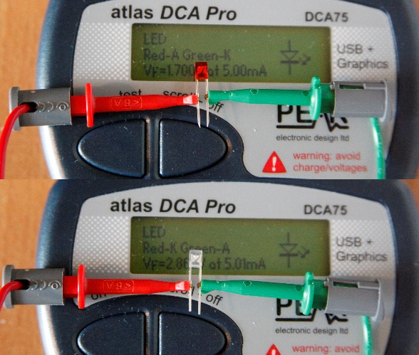
I thought long and hard about what LEDs to use. Yes, the package size is similar, but look at the brightness: 45/35 mcd. Recommended is more like 300 mcd. And the green is 571 nm, more of the yellowy-green. (Look also at the forward voltage, true green is always around 3.3V.)
-
People interested in MBCV v2 should get onto this with transparent clear knobs. It's very likely some sort of illuminated encoder will be implemented.
-
On a sort-of side note, I've tested both the Bourns and Sparkfun illuminated encoders for brightness. I'd guess both are actually made by Topup corp judging by the very similar packages. The illumination is sufficient when I used some analogue PWM, although I don't have clear "Waldorf" knobs.
It's now a question of this easy solution or a cheaper option with hollow shaft ones. It would be possible to bend a square/flat 5mm RGB LED across a PCB cutout, or maybe there's an SMD version that would fit into the 3 mm hole on the same side of the board.
-
This won't work, because this way you will create a non-linear resistor network.
There is no solution to turn a 50k fader into lower resistances, the high fader resistance is prone to jitterBest Regards, Thorsten.
Okay, I was afraid of something like that. Is the 1k too low? If yes then there isn't a lot of alternatives I'm afraid. Unless somebody wants to order the MOQ of 750...
-
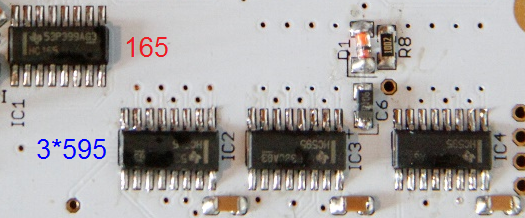
No problem! Yep, the pinout is just what we need to stack the diode on top. Pin 3 to the bottom right is NC for the BAT54 in this package, so you can connect it or not. Better than trying to jury rig a through hole one I figure.
-
Did you ship everyone's PCBs? I expected to get mine with the case
You should probably post this sort of question in the bulk order thread...
Yes, all PCBs were shipped together on the 25th of September. Cases are coming direct to you from the manufacturer from mid-next week.
EDIT: DHL tracking shows successful delivery as of 05.10.2015, 12:57 pm.
-
You can (and should) wait to put the sliders in last. I suggest holding off until your case arrives, place them in without soldering, then see if you're happy with the length. 10k works just fine and is the value recommended for AIN (but apparently 5k is better). Let's wait until TK. chimes in with his knowledge.
20mA is the max for each LED, but they are running through a scan matrix. So it's more like 2 mA per LED. A beefy PSU is recommended, you could consider a switching 5V regulator in place of the 7805.
-
Cases have now entered production with an estimated ship date of October 14.
In regard to Mouser orders, you may wish to wait for a clearer picture on sliders. The 10mm shaft is probably preferable, but we need to check the optimal resistance value as this product range is limited to 1k and 50k from Mouser. The 20k has a centre detent (apparently not too difficult to remove) but might sill be a bit too high.
-
Discussing with TK. the optimal slider value would be 5k. The MOQ of PTL45-10(X)0-502B2 is 750 pieces but I've asked Mouser if they would stock them. Sadly they don't seem to be readily available from other suppliers.
50k and 1k are available in 10mm shaft. Might a good solution then be to order the 50k version then solder a 5k6 resistor in parallel to make about 5k? In general does this technique give satisfactory (i.e. noise-free) ADC in the PIC?
-
Great! It took a whole Sunday afternoon with a huge ultra-thick cardboard box I found, a borrowed jigsaw with a soft material blade and about 5 rolls of tape. I was very thankful for the jigsaw!
One worry I had was the post might use it as a frisbee, but from what I'm hearing no problems so far. I didn't write "FRAGILE" because that apparently increases the chance of damage!
Now you have to choose the LED colours

-
Beautiful work, lovely colours! I'll try to find a source for 10mm sliders in 5k.
-
I can slip you into the case order if you really really want, have a think over the w-e ;)
-
Very nice :)
-
1
-
-
Welcome!
Please find the build guide and BOMs here:
-
Here I will document the parts list and build guide for all BLM users. Once there's a bit more knowledge a wiki page could also be written.
BOM:
http://www.mouser.com/ProjectManager/ProjectDetail.aspx?AccessID=e31c510729
                      Quantity  Recommended     Description
Resistors
660-MF1/4DC1002F      4	        4	        10k through hole
652-CR1206FX-1002ELF  41	100	        10k 1206
652-PTL45-15R0-103B2  4	        4	        10k slider, 15mm shaft, red LED
652-PTL45-10G0-102B2  -         -               1k  slider, 10mm shaft

Resistor networks
652-4816P-T2LF-10K    5	        6	        10k bussed (165 pullups)
652-4816P-1LF-1K      5	        6	        1k isolated (current sinks)
652-4816P-1LF-220     5	        6	        220R isolated (green LEDs, also red LEDs)
652-4816P-1LF-56      5	        6	        56R isolated (blue LEDs)

Capacitors
647-TVX1C471MAD	      1	        1	        470uF electrolytic axial
80-C1206C104K5R	      23	50	        100n ceramic 1206
647-F931C106MAA	      5	        10	        10uF tantalum 1206

Diodes
512-BAT54	      36	100	        Schottky diode SO-23
512-1N4148TR	      289	300	        1N4148 diode
78-LS4148-GS18	      5	        10	        4148 quadroMELF

LEDs
604-APTR3216ZGC	      289	300	        LED green 1206 reverse mount
604-APTR3216QBC/D     289	300	        LED blue 1206 reverse mount
604-APTR3216SURCK     -         -               LED red 1206 reverse mount

Transistors
512-BC81840MTF	      36	100	        NPN BJT SO-23

ICs
595-SN74LVC1G17DBVR   3	        10	        Schmitt trigger, overvoltage tolerant SO-23-5
595-SN74HC165DR	      5	        10	        74HC165D SOIC
595-SN74HC595DR	      15	20	        74HC595D SOIC

Connectors
523-T3507-000	      1	        1	        DIN 8 panel connector
523-T3504-001	      2	        2               DIN 8 plug
---                   2         -               2x5 DIL header male, snap from a larger piece
---                   1         -               2x5 IDC plug female (miniCore)

Hardware
---                   40cm      -               10-way ribbon cable
---                   20        -               M3 nut (stainless)
---                   20        -               M3 washer (stainless)
---                   1(+4)     -               M2 grub screw, 14 mm (stainless)
---                   1(+4)     -               M2 nut (stainless)
---                   1(+4)     -               M2 washer (stainless)
---                   2         -               M3 standoff, 12mm male-female
---                   8         -               M3 standoff, 25mm (for spacing PCB)

Buttons
---                   18(19)    -               adafruit 4x4 silicone

Spacer
---                   1         -               spacer cut from 3mm opaque acrylic
Parts notes:
- You can choose whether you go for Blue+Green LEDs (recommended) or Blue+Red. You could interchange some Green for Red. Green+Red is not recommended as the colour mixing is poor.
- Slider height: I specified 15mm shaft sliders, you could change these for 10mm. 15mm will protrude 13mm out of the case, which might be a bit long. 10mm will only protrude 8mm, so they would be less likely to break off and will probably be a bit more sturdy. TK. suggests 1k should work, the others are too high in resistance to get good jitter-free values.
- You should use the indicated panel mount DIN, but a cheaper pair of DIN8 plugs might work.
- M2 hardware is a bit difficult to find in normal stores, but Boltbase on eBay has good deals.
Tools needed:
- Soldering iron, I managed with a normal tip but it’s a bit tricky with some components
- Solder, probably leaded. 0.5mm will make the finer pitch stuff easier but again I managed with 1mm
- Desoldering wick and/or solder pump. Useful when the pads get too much solder
- Tweezers to pick and place components
- Cutters for diodes and a few through hole components
- Good eyes or light and a loupe
- 2-3 small clamps
- Flat work surface
- Multimeter, test continuity between pads
Build notes:
The BLM is not particularly difficult to build but there is quite a bit of repetition. I advise to complete one section at a time before moving on.Soldering order:
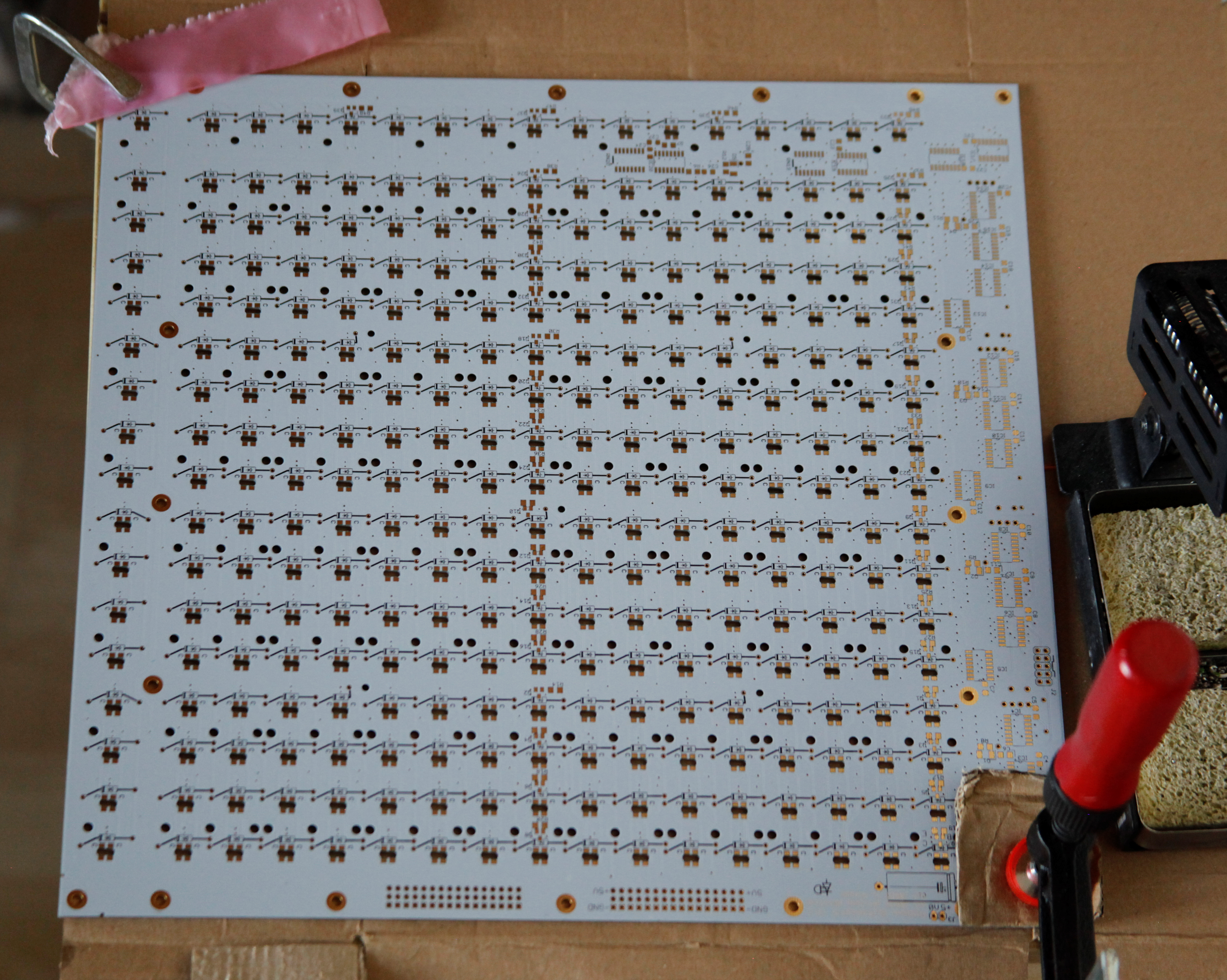
First up, there are 289 through-hole diodes on this board. It might be smart to get all diodes pre-bent and trimmed before doing anything else. The legs should be cut as short as possible before soldering otherwise the button pads won’t sit flush. If you cut the diode leads they tend to fall out; this can be a bit frustrating. Some diodes also overlap with the transistors, make sure they don’t electrically short. So you may wish to solder all of the transistors first, followed by the diodes. Read on for suggestions on mounting these. The down side with this way would be that it’s easiest to put the LEDs in when there’s nothing else on the board… please have a go and share your experiences.I suggest that the PCB is initially clamped (using a scrap piece of material to protect it from the clamp) to the work space, otherwise your parts may jump around if the board gets bumped. If it is truly flush with your bench it will also help to keep the diodes/solder from going through the plated holes. Try to protect the exposed button pads on the PCB top by using a piece of clean paper or other material; don’t damage the surface by scratching it.
LEDs are a little bit sensitive; don’t heat them for more than about 2 seconds at a time and apparently they don’t like static discharges... As far as I know, the humidity warnings you get with them are only really applicable to oven reflow soldering.
So: let’s go!
First up you should tin the pads on the rear side only. I recommend clamping the board at a right angle so you can easily go down a “row.” Tin at least the LED anodes (just the top pad!), but you could do one pad of every SMD component (over a few days it will get harder to “wet” the solder as it oxidises). It will be easier to “tack solder” if you choose a pad which isn’t part of the ground plane. Avoid pre-tinning pads with thermally isolated connections to ground.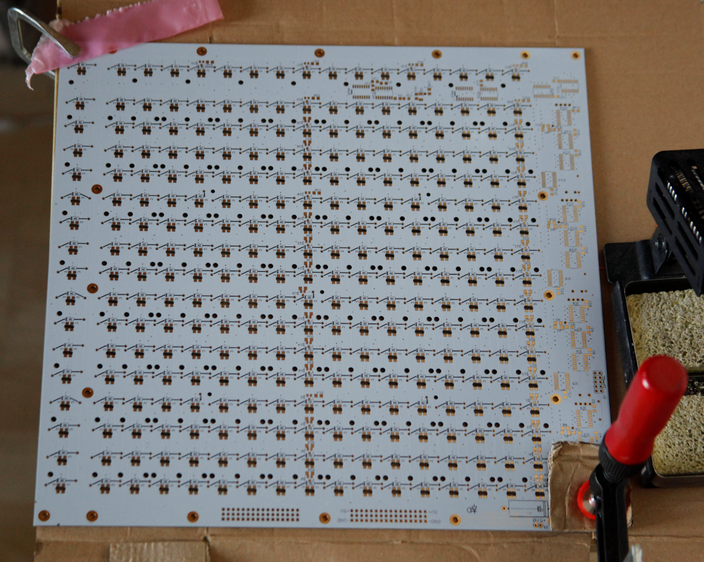
(here the top side is actually at the bottom)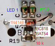
289*LED 1
Actually left on the PCB rear. Ensure the “C” symbol is oriented with the PCB silkscreen. Or you can think of it as making a “T” when the board is viewed the correct way up.
(N.B using the default firmware LED1 is the main step indicator and LED2 is used as the cursor for most modes.)Take a rest.
289*LED 2
Actually right on the PCB rear.
Take another rest.Once these are placed you can go back and finish all of the cathodes, also touching up the anodes if needed.
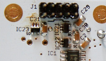
3*SOT23-5 Schmitt buffers (IC21-23)
Located near header J1. These are pretty tricky, so go slowly and use as little solder as possible. Clean up with braid if needed.
36*BC818 transistors (remaining SOT-23 footprints)
Orientation is fixed, again don’t overheat them! Note the line of transistors down the centre of the board (when viewed from the back), another at the left plus 4 more along the bottom.36*BAT54 Schottky diodes
This BLM has a small issue with ghosting (some LEDs are dimly lit when they aren't supposed to be). A fix involves soldering a BAT54 diode 1:1 on top of the transistor, this is hard to photograph but if the solder blobs are big enough they will span from the SMD pads all the way up to the BAT54. Not so big that they short out the two adjacent transistor pins! You may want to see if you are happy with the ghosting before applying this fix; it's only noticeable in complete darkness.36*1206 10k resistors
Some silkscreen values are missing, sorry about that! They are located next to each BC818 transistor (+BAT54).
Don’t worry if solder bridges form from the resistor to the transistors, the pads are common. But don't short out both ends of the resistor!+5*1206 10k resistors (R8-R12)
These form the 4 power on delay circuits located at the left, plus one on the bottom.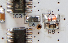
5*MELF diodes (D1-D5)
They are polarised with the black band oriented towards the silkscreen corner line.5*10uF tantalum caps (C6, C11, C16, C25, C28)
Orientation is very important with the grey band towards the silkscreen corner line and + symbol. TANTS MAY CATCH FIRE/EXPLODE IF MOUNTED INCORRECTLY!23*1206 100nF ceramic caps (remaining 1206 pads with rounded corners)
Located next to each IC.Note C26/C27 and R6/R7 don’t need to be installed unless you want to terminate the SC/RC lines, it works fine for me without these.
289*1N4148 diodes
These MUST be soldered on the SAME SIDE AS THE COMPONENT with the leads clipped as short as possible BEFORE soldering. Solder just enough to wet the “bottom” pad. If too much solder is applied then the button surface won’t be flat and the pads will be uneven. A flat work surface will help to keep the solder from reaching the PCB “front.”The other way is to place all the diodes without trimming (making use of spacers attached to the PCB corners), then chop the leads. If you do this they have a tendency to fall out when you flip the board, but it works. Similarly they MUST be soldered from the rear i.e. the same side as the component is placed.
Be careful with diodes that are placed over a transistor or one of the few that have their legs bent out of the way to avoid a mounting hole, they need slightly different lead lengths.
Take another rest.
5*74HC165 (ICs 1, 5, 9, 13 and 17)
15*74HC595 (remaining ICs)
Now attach standoffs to the corners and flip the board to mount the resistor networks:
5*10k bussed (RN1, 5, 9, 13, 17)
Note that these are POLARISED according to the silk screen.5*1k isolated(RN2, 6, 10, 14, 18)
You can follow the silkscreen but it doesn't matter here.5*56R isolated (RN3, 7, 11, 15, 19)
if using blue LEDs for colour 1.5*220R isolated (RN4, 8, 12, 16, 20)
if using green LEDs for colour 2, also for red LEDs.RN19 and 20 are on the rear of the board
Through-hole components:
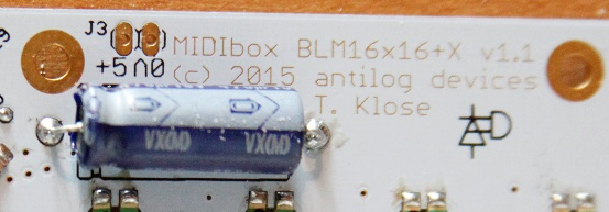
470uF electrolytic (C1)
The “minus” end is marked with an arrow, the “plus” end has an indent aligned with the silkscreen.
Sliders (on the front of the board!)
Sliders are 60mm long and spaced 60mm apart, so they fit together exactly. Mount all 4, then start by soldering one leg. Check the slider is absolutely flush against the PCB before continuing with the remaining legs.Current limiting resistors for the sliders' LEDs (can wait to check the brightness)
You can swap the LEDs with common “2x3mm” sizes. Note the different pinouts:
Please bridge R1 with a piece of wire.
Then solder the 2x5 DIL headers. Now you can apply power to the board (either through J1 or J3) to check the LEDs and choose the through hole resistors that set the LED sliders’ brightness. 10k was good for me. Note: please don’t send clocks/serial data to the BLM with the board’s power disconnected, it might damage the CMOS.
If a Core/miniCore module is connected then without MIDI input the LEDs should light with each button press (just use a loose button pad) in sequence: LED1, LED2, LED1+2, and off again.
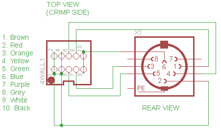
Cable wiring:
Crimp a 10 pin IDC connector on about 40 cm of ribbon. Then solder the following pins on the DIN8 socket in order. It should be possible to do this outside the case and thread the IDC through the mounting hole. Thereafter a DIN8 cable can connect to the corresponding SEQ BLM connector, but you may want to wait to install everything together in the case.
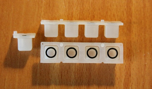
Button pad preparation:
Carefully cut 16 pieces of 1x4 buttons ensuring each has the two guide nubs at the bottom. I recommend scissors instead of a knife to keep it tidier as the silicone tends to unhelpfully flex under a knife. Also cut the corners off pads where M2 grub screws will enter from the front. Now the button pads may be placed (oriented so the nubs fit in the correct PCB holes). It’s best to go from one side to the other to keep everything flat.

Spacer
Then place the acrylic spacer on top (mine is a bit different). There are extra rings of acrylic which can be used as “washers” to make up for the top and bottom right corners. You might want to add thinner metal washers as well to get the distance right.When ordering the spacer (e.g. from Formulor or Ponoko) make sure to choose opaque acrylic in 3mm thickness, probably white or black is best. If you buy milky or clear plastic some LED bleed might occur.
Apparently this one is better optimised into vector format, many thanks Phatline:
BLM_spacer_3mm_Formulor.eps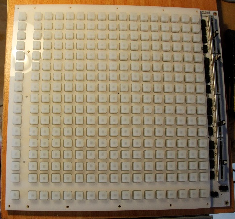
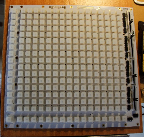
Case assembly
Lift the PCB into the case from the bottom (so your 289 buttons don't fall off) and loosely attach at least a few corners with M3 nuts. You need at least the centre M2 grub screw and can add the other four M2 screws if you feel more stability is needed. It’s probably best to thread them through the PCB from the rear; be careful as the thread pitch is quite fine (0.4 mm) and is cut into soft aluminium. I haven’t noticed any unscrewing, but you could add a drop of Loctite to be sure.Two M3x12 MF spacers attach on the top left corner (viewed from the back), this is where the miniCore will go.
Next tighten the remaining nuts evenly; don’t overtighten as the PCB will flex! As long as the button pads were placed more or less in the right place they should sit evenly above the front panel. Or they may require reseating to get things even.
Attach the miniCore module and a ribbon connector to J1 and panel mount the DIN socket. You need to jumper 4 unused AINs on the miniCore's J5B to ground which will prevent noise on these inputs.
Then close up the case, attach the bottom feet and you’re done!
Congrats on finishing your BLM and I hope you enjoy using it!
Extras:
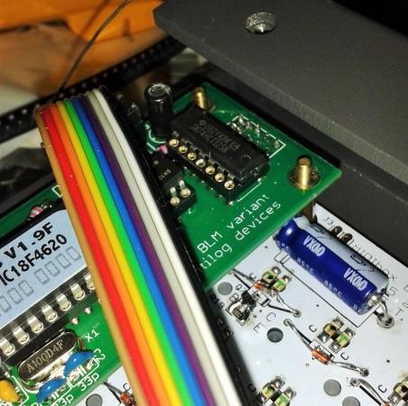
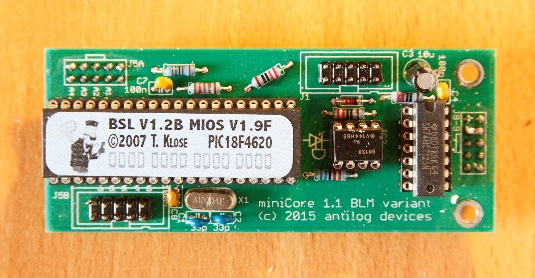
I (or somebody else) will likely design a protection circuit so the extra AINs (4 available) can be used to control parameters on the SEQ. Modular voltage levels are NOT RECOMMENDED without this protection as outside the 0-5V range they will damage the PIC.miniCore:
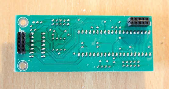
Nothing too special here, just remember to mount the resistors first (i.e. before the DIP40 socket). The BLM data lines are buffered on the main PCB so potentially the 74HC125 chip could be left out. Also keep in mind that the female DIL header sockets must mount on the rear of the board. You can see that I made do with SIL versions that I cut into rows of five.Note: you can also use a PIC18F4685, currently stocked by SmashTV.
BOM:
http://www.mouser.com/ProjectManager/ProjectDetail.aspx?AccessID=28e54a7e6f
                      Quantity  Description
Resistors
660-MF1/4DC1000F      1	        100R
660-MF1/4DC2200F      3	        220R
660-MF1/4DC1001F      3	        1k
660-MF1/4DC1211F      0	        1k21 (replaced by 1k and included above)
660-MF1/4DC5601F      0         5k6 (replaced by 4k7)
660-MF1/4DC4701F      1	        4k7, solder in the 5k6 position
660-MF1/4DC1002F      2	        10k, also usable for slider LED brightness in main PCB

Capacitors
810-FK18C0G1H330J     2	        C1,C2 33pF ceramic, 2.5mm spacing
594-K104M15X7RF53H5   3	        C4,C7,C8 100n ceramic through hole (pull legs tightly through PCB bottom)
667-EEU-HD1H100	      1         C3 10uF electrolytic 2.5mm spacing

Diode
512-1N4148TR	      1	        1N4148 diode (can be taken from the 300 ordered with the BLM)

Crystal
815-ABL-10-B2	      1	        10 MHz Crystal

ICs
595-SN74HCT125N	      1	        74HCT125 quad buffer/level shifter
512-6N138M	      1	        6N138 optocoupler
---                   1         PIC18F4620 from smashTV or other suppliers. Needs MBHP bootloader flashed.

Hardware
517-929852-01-05-RA   2         2x5 DIL female header
---                   2         2x5 DIL male header (snap from larger piece)
517-4840-6000-CP      1	        DIP40 socket, quite expensive, try a local supplier
---                   1         DIP14 socket
Parts substitutions:
Change 1k2 resistor to 1k
Change 5k6 resistor to 4k7

miniCore firmware:
1) The blm_scalar_v1_1 firmware can be downloaded from http://www.ucapps.de/mios_download.html
It contains prebuilt hex files for various hardware configurations:
-
project_without_ain.hex
- without AIN enabled (use this if J5 pins not connected to ground)
-
project_with_4_mapped_ains.hex
- for Latigid On's BLM PCB layout, only 4 faders used
-
project_with_4_unmapped_ains.hex
- AIN pins are mapped 1:1 (n.b. when using the BLM PCB/miniCore the sliders 1-4 are reversed in this configuration)
-
project_with_8_mapped_ains.hex
- for Latigid On's BLM PCB layout if 4 faders + 4 extension AINs are used. It's recommended to jumper any unused AINs to ground
-
project_with_8_unmapped_ains.hex
- AIN pins are mapped 1:1 (n.b. when using the BLM PCB/miniCore the sliders 1-4 are reversed in this configuration)
2) if you are using a PIC18F452, it's required to change the PIC device configuration while flashing the bootloader: the brown out reset level has to be changed from 4.5V to 2.7V as shown in this picture:
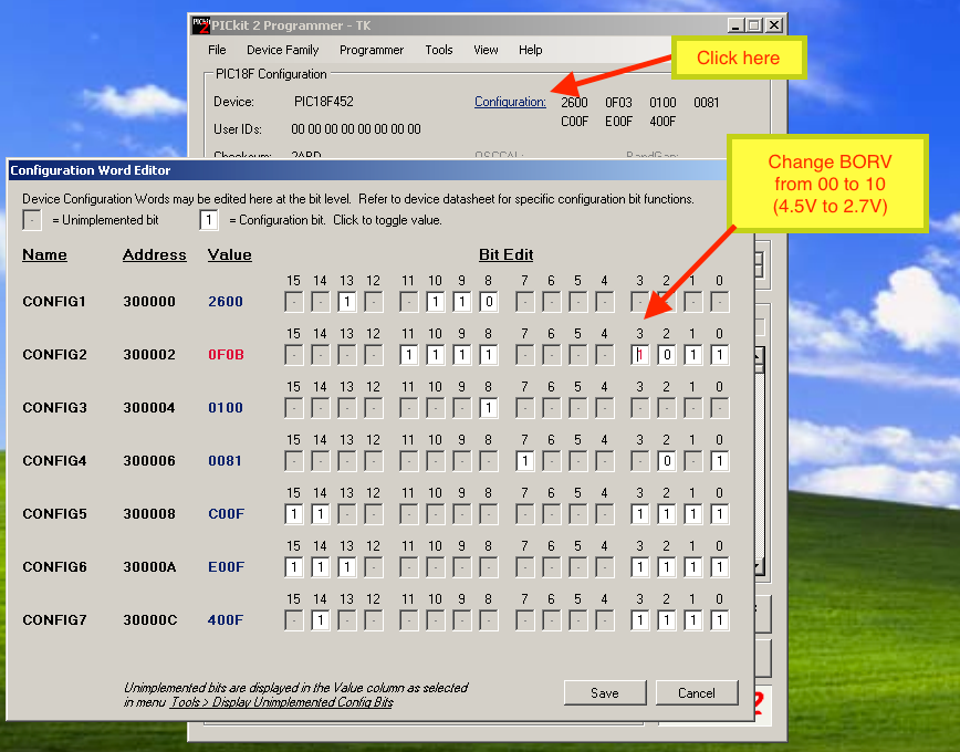
Otherwise PIC could be reset sporadically (depending on the number of enabled LEDs) because the voltage level could fall below 4.5V!
This change is only required for PIC18F452, other pics (such as PIC18F4620 and PIC18F4685 will work w/o this change).
Unfortunately this change can only be done with a PIC programmer. Please contact TK. if you don't own a PIC programmer. He could send you a replacement PIC18F452. Alternatively use a PIC18F4620 or PIC18F4685 if you own one.Acknowledgements
Many thanks to TK. for a great concept to begin with and for providing firmware support to get my kludged prototype working.
And to all builders: thanks for trusting me, it's not too cheap for DIY but I hope you agree the end product is worth it.Addendum
It seems like some form of local power regulation is needed to ensure stable operation. As noted above, some PICs have brown-out detection built into the bootloader, so when many LEDs are lit, the PIC resets and won't work until the voltage rail stabilises over +4.5V. The simplest way I found was to interrupt the 5V line after the DIN socket (inside the BLM case) and add an adafruit Verter Buck Boost regulator. Mounting is stable using a SIL header on one row of the blank muck space, this can be connected to the unused functions on the small PCB.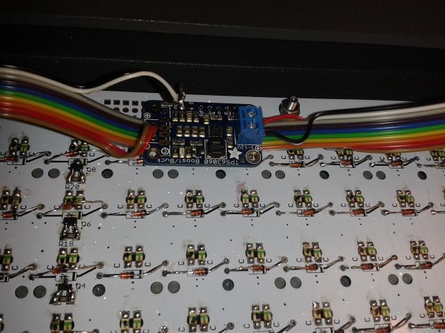
Power consumption
- Using the Verter, standby voltage and current is 5.2V and about 30-60mA.
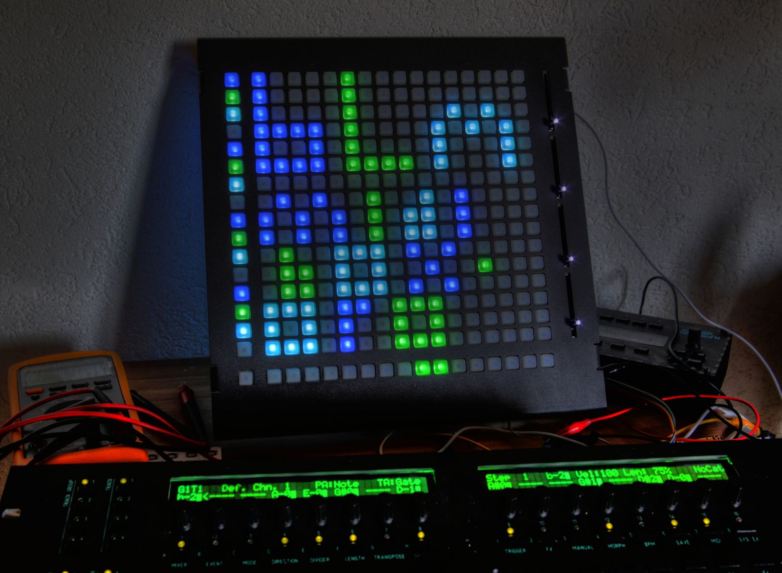
- With all LEDs lit (both colours) the draw goes up to 647mA, although this would never be done in normal operation.
- In track mode with all 16x16 blue LEDs lit the draw is 467mA and the voltage drops to 4.72V. I don't really perceive a difference in brightness, but it could only be a good thing! As long as the ADC inputs are scanned relative to the supply voltage you shouldn't lose control at the top end.
-
2
-
so what's the scoop on cases?
They're just preparing the production files so it might be finalised this week.
-
Insider knowledge! Please solder the Schottky diodes on top of the NPN transistors as this completely eliminates the ghosting. A bit unconventional but hey, DIY!
I will upload the BOM very soon, I promise.
-
Thanks for letting me know!

I have my Schottky diodes, so I hope to install those tonight. The BOM from Mouser should then be complete and you can place your orders. I am also finalising delivery of the cases, no definite ETA on those yet.


RGB hue sweep
in MIDIbox NG
Posted
Thanks for the tests! Can I ask the specs/datasheet of the LEDs you are using i.e. luminous intensity in mcd? And when you say "directly to DOUT pins" were you using current limiting resistors? I think these will be needed to smooth out differences in brightness one often sees with RGB LEDs, not to mention the lower forward voltage for the Red die.
Without matrix connections the PCB will also be much simpler to route :).