latigid on
-
Posts
2,524 -
Joined
-
Last visited
-
Days Won
149
Content Type
Profiles
Forums
Blogs
Gallery
Everything posted by latigid on
-

Full 16x16+X BLM with silicone buttons, matching case. Interested?
latigid on replied to latigid on's topic in MIDIbox BLM
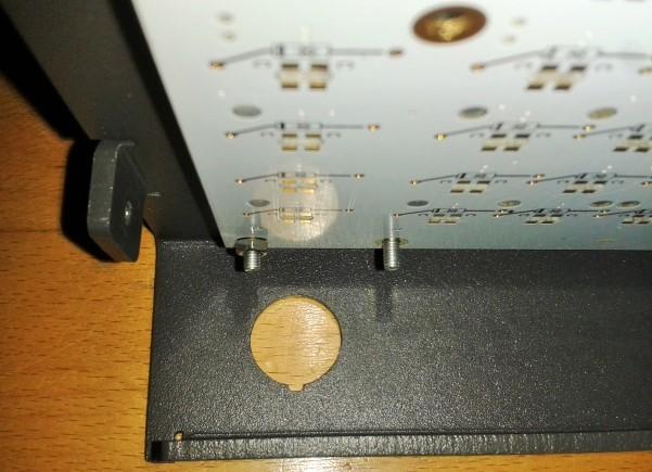
This shows the internals, I don't think it's possible to fit both in a vertical line. Horizontal I can do, the green outlines are 10 mm. But of course it's nicer to have all the cables out of the way on one side.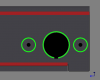
-
Full 16x16+X BLM with silicone buttons, matching case. Interested?
latigid on replied to latigid on's topic in MIDIbox BLM
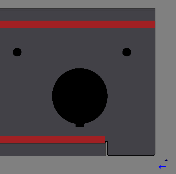
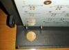
Is this okay for you? You would have at least 14 mm diameter clearance. Feel free to suggest another idea if you like, the red zones are essentially where the case bends. Remember that this is aluminium, not steel, so it is no trouble to drill if you wanted to wait until you have all the parts at hand. It's a bit difficult to place the holes without seeing the parts you're using. Everything is more or less working, but I should test a new PCB to be sure. If you like there's a waitlist for the next batch in the Bulk Order section.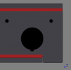
-
Full 16x16+X BLM with silicone buttons, matching case. Interested?
latigid on replied to latigid on's topic in MIDIbox BLM
Looks like it shouldn't be a problem to optionally add holes for power switches (I will confirm orders and collect addresses etc.). To check: the switch and barrel connector holes are 13x12 mm and 11.1x9.1 mm as per TK's Schaeffer file? I notice a lot of SEQs with a lot of different power entry requirements, I'd have to settle on one design. -
BLM 16x16+X PCB and case order [CLOSED/waitlist]
latigid on replied to latigid on's topic in Bulk Orders
Waitlist PCB BLM PCB miniCore Case Shift button M2 hardware 4xLED latigid on 1 1 1 1 1 1 Total 1 1 1 1 1 1 -
BLM 16x16+X PCB and case order [CLOSED/waitlist]
latigid on replied to latigid on's topic in Bulk Orders
Name PCB BLM PCB miniCore Case Shift button M2 hardware 4xLED latigid on 1 1 1 1 1 1 Rowan 1 1 1 1 1 1 Phatline 2 2 1 2? 1 1 TK 1 1 1 1 1 1 Altitude 1 1 1 1 1 1 rwo 1 1 1 1 1 1 jojjelito 1 1 1 1 1 1 tashikoma 1 1 - 1 - 1 workspace 1 1 1 1 1 1 flyweight 1 1 1 1 1 1 Grizz 1 1 1 1 1 1 blingy 1 1 - 1 - 1 ganchan 1 1 1 1 ? 1 Macotronic 1 1 - - - - sbm 1 1 1 ? ? 1 Jack 1 1 1 ? ? 1 tabularasa 1 1 1 ? ? 1 sonicwarrior 1 1 1 ? ? 1 jbdiver 1 1 1 ? ? 1 Total 20 20 16 14(+5?) 10(+6?) 18 Okay, I will have to CLOSE this order now, mostly because of the shipping effort from my side. All others who are interested can go on a waiting list for the next batch or jump in if people above are too slow to pay etc. -
With a scope or multimeter you can see if the power rails stay stable. You can also measure current levels and compare the difference between your LPC17 and STM32 cores. Note that the LPC17 has 780X regulators which should be good for 0.5A without heatsinks. How is the +5V regulated on the STM32F4 board?
-
Are you using USB power? Can you monitor the appropriate supply voltages?
-
Why not go for the maximum PCB size? A bit more symmetrical this way.

- 40 replies
-
- 1
-

-
- MBCV
- illuminated encoders
- (and 1 more)
-
First option is to buy the single version (MCP6001). Next best is to wire the inverting input and output together with the non-inverting connected to a potential between the power rails (e.g. make a 1:1 divider with two resistors). http://www.analog.com/media/en/rarely_asked_questions/RAQ_unused_op-amp.pdf Btw, it looks like you're trying to power your circuit through I2+?
-
Hi, yes I've seen this, many thanks. I will probably develop a single PCB version at least for my own needs, but community feedback is always welcome :)
-
You could try the MCP6002 for a cheap trial. In the end it still makes sense to use a bipolar PSU I think.
-
Note: I've just re-remembered sneakthief's MBCV enclosure in the other thread. It would be good to know if the button layout is optimal. My plan is to use encoders with push buttons, so there's a few extra degrees of freedom.
-
Hmm, seems like I've forgotten about your case. Meanwhile I've opened a new thread to discuss an all-in-one PCB with illuminated encoders in place of LED rings. I'm interested in how the button assignments are working out.
-
If you want to use a single supply, choose a rail to rail op amp or bias the input (or just use a bipolar supply, this is a much better idea). The op amp won't swing close enough to the PSU rails for it to be useful, i.e. you will have a constant DC offset.
-
BLM 16x16+X PCB and case order [CLOSED/waitlist]
latigid on replied to latigid on's topic in Bulk Orders
Name PCB BLM PCB miniCore Case Shift button M2 hardware 4xLED latigid on 1 1 1 1 1 1 Rowan 1 1 1 1 1 1 Phatline 2 2 1 2? 1 1 TK 1 1 1 1 1 1 Altitude 1 1 1 1 1 1 rwo 1 1 1 1 1 1 jojjelito 1 1 1 1 1 1 tashikoma 1 1 - 1 - 1 workspace 1 1 1 1 1 1 flyweight 1 1 1 1 1 1 Grizz 1 1 1 1 1 1 blingy 1 1 - 1 - 1 ganchan 1 1 1 1 ? 1 Macotronic 1 1 - - - - sbm 1 1 1 ? ? 1 Jack 1 1 1 ? ? 1 Total 17 17 13 14 10 15 -
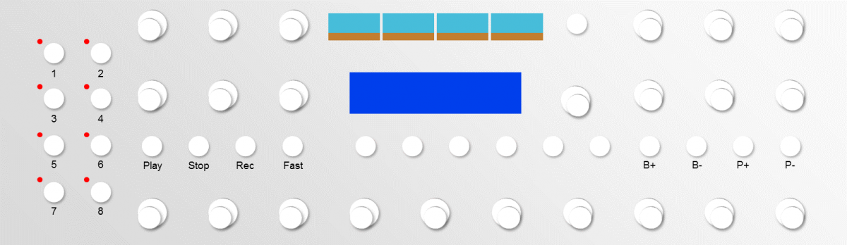
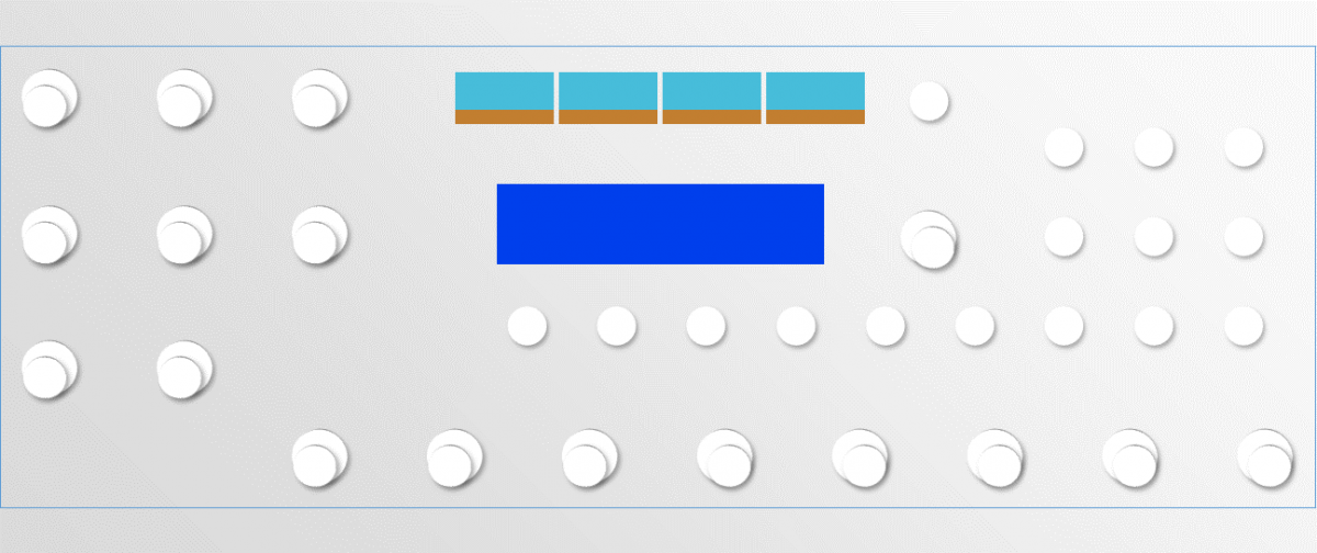
We've seen the for the time being there aren't any working examples. The LRE8x2 boards are unfortunately not readily available, and there are a few issues with getting components mounted (GLCDs) and at the correct height. I would like to propose an alternative front panel, here are some rough concepts below. The window size is the previous idea, with the frame representing a smaller PCB. Some differences: 1. Smaller PCB. This should fit in a 3U case, just like the SEQ v4 2. Illuminated encoders in place of LED rings. Different encoder layout 3. GLCDs mounted above SCS and accessed with the same buttons 4. All DIN(/DOUT) on board. Optional open collector buffers (7407) or other level shifters to allow for higher voltage gate/clock signals. Illuminated encoders would be something new for MIDIbox. These would consume less power and DOUT pins, and require only one hole per encoder. Metal panels would be an option. I would have to check the illumination and quality before committing to a design. Two methods of controlling them are either special PWM code through a DOUT (about 4 levels per colour) or a dedicated PCA9635 (or other) driver running off the I2C buss (256 levels per colour). TK notes that the update rate would be slower with the second option, although the PWM clock is 1 MHz. Encoder types could be RGB or RG, this is something to discuss. With a custom PCB we can have a purpose-built front panel, so I welcome proposals for encoder and button layout. People familiar with MBCV should note what the most important/useful functions are and we can go from there.
-
BLM 16x16+X PCB and case order [CLOSED/waitlist]
latigid on replied to latigid on's topic in Bulk Orders
Name PCB BLM PCB miniCore Case Shift button M2 hardware 4xLED latigid on 1 1 1 1 1 1 Rowan 1 1 1 1 1 1 Phatline 2 2 1 2? 1 1 TK 1 1 1 1 1 1 Altitude 1 1 1 1 1 1 rwo 1 1 1 1 1 1 jojjelito 1 1 1 1 1 1 tashikoma 1 1 - 1 - 1 workspace 1 1 1 1 1 1 flyweight 1 1 1 1 1 1 Grizz 1 1 1 1 1 1 blingy 1 1 - 1 - 1 ganchan 1 1 1 1 ? 1 Macotronic 1 1 - - - - Total 15 15 10 14 10 13 FYI, you can keep the table tidy by using the code "< >" formatting. The shift button and M2 hardware are now maxed out. If you're still interested just put a question mark on these and if it goes over 10 I'll consider ordering more. -
BLM 16x16+X PCB and case order [CLOSED/waitlist]
latigid on replied to latigid on's topic in Bulk Orders
Please see post above: if you don't fit into a multiple like 10, 15, 20 PCBs etc, then you can go onto a waiting list for the next batch. Let's see how many are requested. Looks like a big trip to the post already! Likewise, no problem for more PCBs or cases. The PCB you will get will be a new revision. -
BLM 16x16+X PCB and case order [CLOSED/waitlist]
latigid on replied to latigid on's topic in Bulk Orders
No limit to the number of cases! PCBs may be subject to certain multiples, e.g. 10,15,20 etc. -
Alternative to LED encoder rings: illuminated red-green encoders?
latigid on replied to latigid on's topic in Design Concepts
Getting closer: -
BLM 16x16+X PCB and case order [CLOSED/waitlist]
latigid on replied to latigid on's topic in Bulk Orders
No problem, I will try to accommodate everyone as best as I can. -
Full 16x16+X BLM with silicone buttons, matching case. Interested?
latigid on replied to latigid on's topic in MIDIbox BLM
Perhaps a question for TK: there is a small amount of "ghosting" e.g. when a sequence is running one LED is dimly lit 8 steps behind the current one. Was this ever seen before? It isn't bright enough to make it through the silicone button but I should mention it and wonder if there's a possible hardware (or software) fix before going for a new board rev. In terms of current, running the entire 16x16 group illuminated blue (i.e. step active) draws about 560 mA. Thus it would be good to have a high current PSU feeding the SEQ; for example, I have a Meanwell 2.5A switching PSU for my 5V line. Unless your musical tastes are quite different to mine, it should usually be around half of this. I did add an extra header for power, and could add a second hole for a connector on the case if requested, if your existing SEQ PSUs aren't juicy enough. Please let me know in advance if this is needed. -
Full 16x16+X BLM with silicone buttons, matching case. Interested?
latigid on replied to latigid on's topic in MIDIbox BLM
Great, please sign up here: -
Alternative to LED encoder rings: illuminated red-green encoders?
latigid on replied to latigid on's topic in Design Concepts
Hmm, there's a few examples of LED driver ICs too: MAX7221 is $10 oer chip... TLC5940 is $3-6 but PDIP marked as end of life. Also Ander's crazy Station, using PCA9635 ($2.50 in TSSOP): -
BLM 16x16+X PCB and case order [CLOSED/waitlist]
latigid on replied to latigid on's topic in Bulk Orders
Thanks Thorsten for the firmware updates to get it working and the brilliant platform to begin with! Looking forward to those other modes, whatever they turn out to be. Och, I should say that I can either take payments via SEPA transfer (I think that's free) or PayPal. But in the latter case I would have to add 4% fees... Just to clarify availability: I'm assuming a new run of 10 PCBs with minor trace fixes, but I might build just one more to be 100% certain... Let me think about this. And I only have 9 pieces of the M2 hardware left, which can be found in hardware stores or easily on eBay from Bolt Base. It's just for convenience's sake, and I won't need them for other projects. I think the white LEDs for the sliders work well with the Blue/Green/Cyan colour scheme, but if you like you can get other colours like red, green, orange (TTSH) etc. as standard directly from Mouser. It's no problem to do a larger PCB run if the demand is there.