latigid on
-
Posts
2,524 -
Joined
-
Last visited
-
Days Won
149
Content Type
Profiles
Forums
Blogs
Gallery
Everything posted by latigid on
-
Also my dilemma; a big part of the Elektron sound is the parameter locks etc. I wonder if there's a way to somehow use the MD in record mode?
-
Hello, welcome to MIDIbox! A main advantage of the SEQ is that you can use many (2/4/8 or even 12) outputs in parallel. You should have no problems this way. I don't know of any hard data, but TK was careful with coding the older models in ASM for the best performance.
-

Full 16x16+X BLM with silicone buttons, matching case. Interested?
latigid on replied to latigid on's topic in MIDIbox BLM
Heh, Abelton just sent me a promo for Push, I should show them this thread :rolleyes: -
Full 16x16+X BLM with silicone buttons, matching case. Interested?
latigid on replied to latigid on's topic in MIDIbox BLM
Many thanks all! Not finished yet! :frantics: -
Full 16x16+X BLM with silicone buttons, matching case. Interested?
latigid on replied to latigid on's topic in MIDIbox BLM
Good to have you on board! Check the first page for a case design. It's 3.18 mm aluminium for the whole thing. I've changed the design to a flatter (25.4 mm front / 50.8 mm back) slope and simplified it to be cheaper. I opted for a dark grey powdercoat as I think it will last better. I'll post pics when I get it from the supplier. -
Full 16x16+X BLM with silicone buttons, matching case. Interested?
latigid on replied to latigid on's topic in MIDIbox BLM
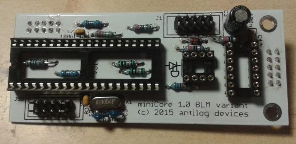
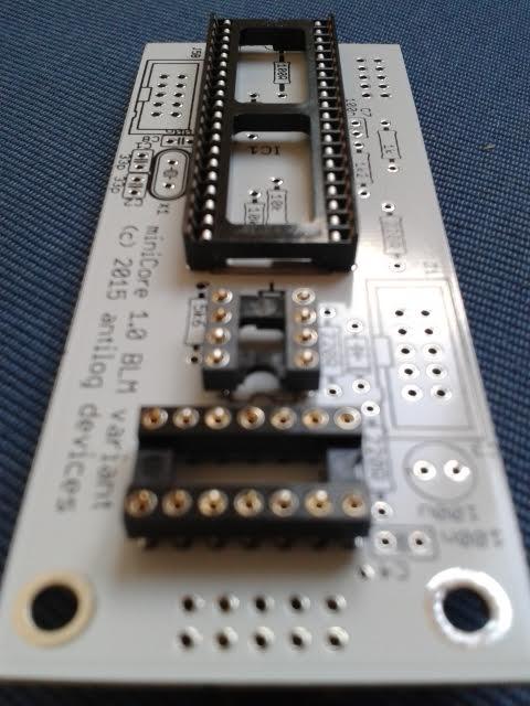
There's a backpack miniCore which I also recommend. Just have to test a new run of these. -
Full 16x16+X BLM with silicone buttons, matching case. Interested?
latigid on replied to latigid on's topic in MIDIbox BLM
PCB: around $75 Silicone pads: $4 to $4.50 from ADAfruit. If there's enough interest I could ask for a bigger discount. Flikto.de has them for 5.20€ with free shipping after 50€. I designed the front panel for an M2 grub screw, not the sort of thing you normally buy so I could also provide these. And white square LEDs for the sliders as you have to buy 100 at a time from eBay. -
Full 16x16+X BLM with silicone buttons, matching case. Interested?
latigid on replied to latigid on's topic in MIDIbox BLM
Thanks! For sure, I have all of the part numbers from Mouser which I will compile for you later. Let me get my case first, but after I've checked I can run a bulk order. For around 5 cases the cost will be less than $300 and closer to $260 for 10 pieces, this includes shipping direct to you. I will see if they are able to run it through their UK branch, then perhaps extra VAT can be avoided for EU folk. -
Full 16x16+X BLM with silicone buttons, matching case. Interested?
latigid on replied to latigid on's topic in MIDIbox BLM
Okay, you've twisted my arm. It's nothing much as I'm still getting used to the different modes. http://youtu.be/bvshXbsrHjg -
Full 16x16+X BLM with silicone buttons, matching case. Interested?
latigid on replied to latigid on's topic in MIDIbox BLM
Can I just say that the implementation of the BLM works impressively well with the SEQ -- hats off to TK. It's really nice to scroll through the tracks and have every one update on the BLM. I can imagine the new step recording will also be great; hold any button and a MIDI key to quickly enter a pattern. Things really start to get wild when messing with the length and direction parameters :). -
Full 16x16+X BLM with silicone buttons, matching case. Interested?
latigid on replied to latigid on's topic in MIDIbox BLM
Hello, I could do a big order from Mouser but being in CH everyone would have to pay extra VAT... there could be a possibility to go to the post if I'm visiting DE. It makes the most sense to bulk order LEDs and the silicone buttons. I have one extra set of 300 blue and 300 green LEDs that I can already let go for cheaper and there's discounts for over 99 pieces of the pads from adafruit. You need 18 sheets per BLM, plus 1/16. I could also provide some of these single buttons to save buying an extra sheet. The other components are readily available from Mouser but it's less effort from my side if everybody orders from them, plus the cost savings are insignificant. As for an update the basic concept is working well with a few tweaks. I am waiting for the case to be made, after that I will start to collect orders in the next few weeks. -
Maybe it's a 8/4 bit LCD issue? What driver type is it? Does this help: ?
-
Isn't it normal that CS isn't enabled for the slaves? The CS can only control/be controlled by one PIC at a time, and that data is forwarded to the others when required (as far as I know). I don't know what's happening with the LCD sorry, but you should check the wiring.
-
From memory you have to get the SID application on every Core individually at the first install. Afterwards you can "clone" updates via CAN (I guess CAN isn't configured otherwise). Nearly there I think! :flowers:
-
There's a hex file you can send via MIOS to change the headers. Once each has the correct ID you can address the intended PIC using the "Device ID" box on the middle-left of MIOS studio. I always query the PIC to make sure the transfer works properly before uploading hex.
-
Please read here: http://www.ucapps.de/mios.html Then flash your PIC with the bootloader. Afterwards, install MIOS Studio on you computer and upload the MB6582 application via MIDI.
-
If you have bootstrapped PICs, do they have the correct device IDs? Are you addressing the right chip in MIOS?
-
Any thoughts on just using three pins with PWM control?
-
This is pretty cool, nice grooves!
-
White soldermask sure shows up the flux residue!
-
Humble pie! :turned: No big deal with the 3M socket, just clip back a bit of the plastic and it fits under just fine!


-
Nice!
-
^^ yep! An upside of this is that they also use less power (i.e. higher efficiency). Generally people stick to linear regulators for audio as the noise can be problematic. But the technology is improving all the time.
-
This should really be a sticky topic, but: the best practise is to use a high-current linear PSU outside of the box and replace the 7805 with a modern switching Vreg. You can then use linear Vregs (7809 or 7812) to supply power to the SIDs.
-
The big BLM will also use these sliders, I have a bunch of white LEDs to go in :)