latigid on
-
Posts
2,524 -
Joined
-
Last visited
-
Days Won
149
Content Type
Profiles
Forums
Blogs
Gallery
Everything posted by latigid on
-

BLM 16x16+X PCB and case order [CLOSED/waitlist]
latigid on replied to latigid on's topic in Bulk Orders
Number of spare BLM/miniCore PCBs: 3 If you want cheap shipping and a cheap case, please let me know by, say 15.09.2015. Obviously I'll have the PCBs until they're sold, but I will only order the number of cases I have payments for. I'll have to consider the interest for another run (not looking likely at this stage), but let's see. -
Heh, again it's an 8-pin connector! This is the one I've bought for my cable: Mouser: 523-T3504-001 It's very nice, but a bit pricey. And with the above mentioned DIN-8 ;) socket, you have to remove the screw collar to get it to mate properly :roll:
-
Eventually I found the correct one on eBay: User: lyn3009 http://www.ebay.com/itm/2-x-8-Pin-DIN-PCB-Sockets-Audio-069-/121655155694? (BTW, 8 pin connector!)
-
Alternative to LED encoder rings: illuminated red-green encoders?
latigid on replied to latigid on's topic in Design Concepts
Heh, I see this is more about the LED ring but it's still interesting to see the RGB encoder... -
Alternative to LED encoder rings: illuminated red-green encoders?
latigid on replied to latigid on's topic in Design Concepts
I would say that we don't know how it will work until somebody (i.e. me) tries it. You have 256 colour levels with RGB LEDs but only 16 with the LREs, although you do have a positional indicator. Remember that exact values can be read out on the associated LCD. So hopefully I have some time to design and test after the BLM is out the door. Interested to see what you come up with, both in terms of electronics (see FantomXR's work above) and also the "engineering" side (panel spacing, getting the light through etc.). -
You mention "affordable" as a main requirement, which will mean something different if you are Mr. Oizo! Something you should realise is MIDIbox is a cool way to get custom hardware, but it's not necessarily going to be cheaper. I've seen many grandiose plans never get past the design phase because they are a bit too ambitious or they realise it will cost $$$. But it's certainly doable! Seeing as you have the Behringers already, you might be able to test the concept of merged data streams with a Core 32, which supports at least 4 MIDI ins and outs. Are you good on the programming side? I'm sure you could mess with the code to process the data however you like, including sending custom sysex streams if needed.
-
I can't remember too many truly massive NGs during the past couple of years, but this was certainly done in the early days of MIDIbox. I would say if you really wanted modular blocks then house each in its own case and send/receive the data by ordinary MIDI. You could then have a master box which merges all of the inputs and sends out the data over USB. For this you would need one Core module per box, and an 8-bit one will do the job just fine. It's possible to send out balanced data signals via the line driver/receiver boards but MIOS works in a chain, not a star. Having multiple Core modules means just one chain per box, rather than multiple line drivers (which is untested as far as I know).
-
I believe that s/he is asking if somebody will develop this controller on commission, I can see how it might be done but I think the cost would be quite high. To OP: what are you willing to pay? I'm not signing up to build it :), but just to get an idea of how much you think it's worth. My guess is that it would be more than you expect. It makes more sense to arrange encoders in multiples of 8 as that's how the shift registers are connected. I can see groups of 2x4, meaning you might get away with PCB mount on many small boards. The button pads are trickier as they must PCB mount, then you have to work out how to secure them. And I'm not sure if there's a MIDIbox application for force-sensing resistors or piezo elements, you might need to search the forum a bit. The case would also be quite pricey, it might be better to first pick an off-the-shelf model and design around that.
-
BLM 16x16+X PCB and case order [CLOSED/waitlist]
latigid on replied to latigid on's topic in Bulk Orders
Still waiting on bank payment from TK., ganchan and flyweight. When you make the transfer, it's best to use USD as requested. If you must specify euros, the amount might not be quite correct and I'll ask for a top-up :). You can use this calculator to get an idea of the exchange rates: https://www.postfinance.ch/en/biz/prod/info/fincalc/change.html -
Full 16x16+X BLM with silicone buttons, matching case. Interested?
latigid on replied to latigid on's topic in MIDIbox BLM
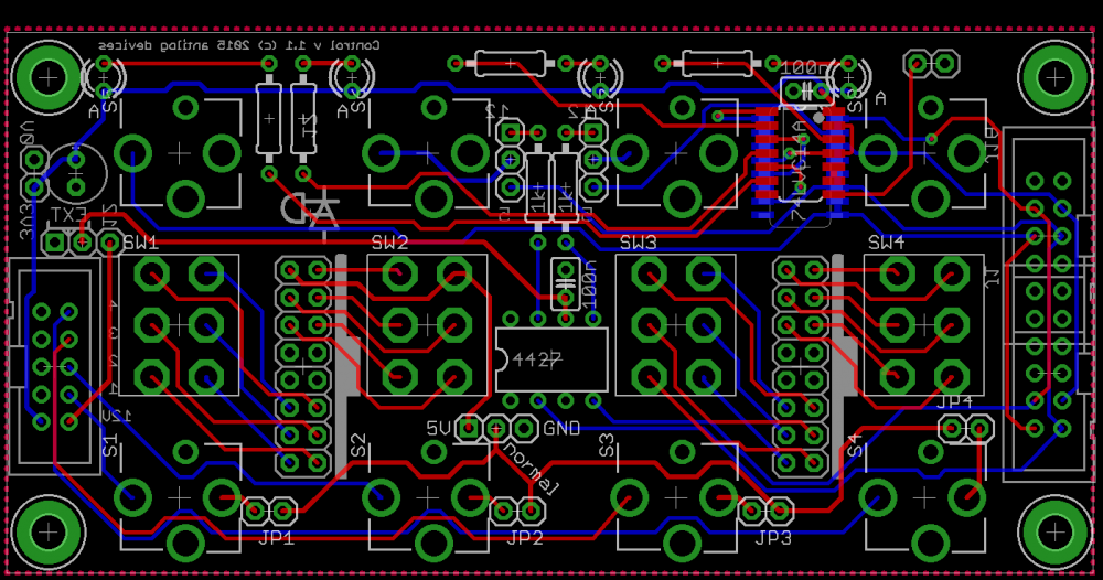
Progress: New additions: More mounting holesHoles centredFixed tracesLPF for PSU (to test)Schmitt triggers on SC, RC and SO lines (keeps clock signals at Vcc to avoid latch-up)Start up delay for /output enable EDIT: can also be controlled by a spare PIC pin if available/if there's code space left (e.g. port B currently allocated to the LCD)Base-emitter resistors, might help with the very faint ghosting. Also necessary when tri-stating the 595 outputs at start upDiscrete components are easy 1206, in fact the most fiddly thing will probably be the 289 THT diodes!Diode bending jig added to a corner (experimental) -
BLM 16x16+X PCB and case order [CLOSED/waitlist]
latigid on replied to latigid on's topic in Bulk Orders
PCBs now at the fab. All going well you will receive them in time for Oktoberfest :) -
I already have PCBs for this (as of yet untested): It's a dual design board for AIN and AOUT of 100x50 mm and includes my range switching ideas (bipolar +5/-5, 0-5 and 0-10). It lines up with my AIN and AOUT boards which would be panel mounted by their attenuator pots and connected through IDCs. DOUT comes in from the right, and there's two channels of MOSFET level shifting. I think the DOUT is mirrored in this case, but as long as you're in the know it's easy to adjust one end of the cable :). There's a hex Schmitt trigger which will condition a clock for AIN and drives LEDs on the remaining 4 channels.
-
BLM 16x16+X PCB and case order [CLOSED/waitlist]
latigid on replied to latigid on's topic in Bulk Orders
Sweet :) -
e-organ, Key-switches to Ground > but Dout Gives +5V how to reverse?
latigid on replied to Phatline's topic in MIDIfication
There are quite a few ways to level shift for gates. It can be done very simply with transistors or the ULN chip as suggested, but you might have to invert the gates in software. It seems a little strange that the low side doesn't swing to 0V, but I'm not too familiar with the chip. 7407 is a hex buffer with open collector outputs, so you can pull up to any voltage you need with the appropriate protection resistor. If you search, I have a PCB design on this forum. I know Altitude and the MIDIALF use CD4504s. I still haven't tested my newer circuit with 4427 dual MOSFET drivers but that should be okay too. More ideas here: https://www.muffwiggler.com/forum/viewtopic.php?t=135374 -
BLM 16x16+X PCB and case order [CLOSED/waitlist]
latigid on replied to latigid on's topic in Bulk Orders
Okay, I've attached it, eventually I'll write up a wiki page. It's based on the "P2" size, 384 mm square. I chose milky acrylic, but I don't see a problem with opaque (?). This EPS file uploads correctly to Formulor, but please verify that everything looks okay before ordering. Because the spacer doesn't span the entire PCB I've added a few extra "washers" to help with the spacing, hopefully they work out okay. You have extra room on two edges if you need anything else done. BLM_spacer_3mm_acrylic.eps -
BLM 16x16+X PCB and case order [CLOSED/waitlist]
latigid on replied to latigid on's topic in Bulk Orders
Good news: http://eepurl.com/bvVCt1 50% discount on materials at Formulor, valid until the end of September. I am still doing final PCB tweaks but hope to order soon. -
I'm tentatively down for about 50 transparent/clear ones :)
-
Strange startup behaviour for shift registers
latigid on replied to latigid on's topic in Testing/Troubleshooting
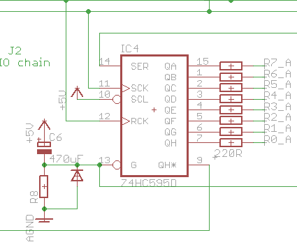
Not so fast perhaps! When I tried moving the resistor to the main board the problem reappeared. The crocodile leads added half an ohm and 0.9 uH each. Trying to tailor this LCR circuit with real components also didn't help. I now think there may be a problem with the current sink drive transistors on the common cathode lines (595 out --1k-- transistor base). Because they have no bias resistor at the base, small leakage currents can propagate which might lead to weird behaviour. So that's probably the first thing to try. Secondly, I've seen examples of using the /OE (output enable) pin to tri-state the outputs at startup. This could be configured in two ways: first is an RC circuit shown below: The cap should probably be 10 uF for a delay of about 150 ms. The resistor at 10k should work, while the diode helps to discharge things when the power is removed. Second is to replace the cap with a 10k pullup, then use a spare PIC pin to drive /OE low only when the SRIO chain is properly initialised (diode and "R8" out of circuit). As an added bonus, pulsing /OE can then control LED brightness, although the utility is reduced in my design as the /OE pins of three separate 74HC595s are tied together to make PCB routing easier. And there's the question of 5 spare pins needed from the PIC (5x SCALAR circuits chained) I've read that you shouldn't leave transistor bases floating (remember DOUTs will be essentially open circuit at startup), so that's another reason for pull downs on the bases. The question remains whether similar pull downs are needed on the 595 outs connected to the LED anodes. I don't want to decrease the current with an additional voltage divider (even though 220R/10k sets up a divider of only 10000/10220, should be insignificant). And I suppose that no current can flow with the transistor off.
-
BLM 16x16+X PCB and case order [CLOSED/waitlist]
latigid on replied to latigid on's topic in Bulk Orders
All current invoices are now sent. I have contacted those who initially signed up, but had changed circumstances, with an option to deposit $100 with me to hold the pricing as it is at the moment. Full payment could be delayed for at least half a year. No problem if this doesn't work at the moment, but the downside will be increased costs in the long run as the current order relies on certain quantity discounts. -
e-organ, Key-switches to Ground > but Dout Gives +5V how to reverse?
latigid on replied to Phatline's topic in MIDIfication
That's what I was thinking, it will totally depend on your actual organ as to what solution would work, but the ULN driver chip is an easy hardware fix for inverted gates. As a bonus, you can supply the chip with a higher voltage and it will act as a level shifter if you need say 15 V for S-trig. -
BLM 16x16+X PCB and case order [CLOSED/waitlist]
latigid on replied to latigid on's topic in Bulk Orders
We continue. I'll send out the bank payment details and remaining Paypal invoices today. -
Shiny forum! Seems like a lot of space though?
-
BLM 16x16+X PCB and case order [CLOSED/waitlist]
latigid on replied to latigid on's topic in Bulk Orders
It's probably best to bulk order in the EU/US. Here are the prices for a set of 18: Mouser single person: $88.02 Mouser 6 people (108): $78.12 ADAfruit single person: $80.28 ADAfruit 6 people (108): $71.28 (the unlucky few who missed out on a shift button need a whole extra 4x4 piece) In my experience, I don't normally pay customs fees or VAT from Mouser if I choose UPS as shipping and order over a certain amount. With ADAfruit these would be added on. I'm a leeeetle bit uncomfortable with bringing piles of button pads and LEDs over the border, even though I realise it would be the most efficient way to ship everything together... Would someone in DE/AT run a bulk order of LEDs/button pads from Mouser and ship them out? It might save $50 per person. -
BLM 16x16+X PCB and case order [CLOSED/waitlist]
latigid on replied to latigid on's topic in Bulk Orders
Hi, great news! I realise many people are on vacation at the moment. I will reply personally to you but I wanted to mention the button availability here. I would recommend buying the silicone buttons from Mouser at the same time as the remaining components. If adafruit have a supply deal with Mouser then it means that they intend to make these for a while yet. And still, they are readily available directly from adafruit but you would of course have to pay for shipping that way. The order from MIDIbox would even be enough to justify a production run for them I think. So: don't panic :) but you could email them if you were worried. I once asked if any larger discounts (hundreds) were possible and got a pretty terse response, but maybe they get that a lot :).