

latigid on
-
Posts
2,524 -
Joined
-
Last visited
-
Days Won
149
Content Type
Profiles
Forums
Blogs
Gallery
Everything posted by latigid on
-

Full 16x16+X BLM with silicone buttons, matching case. Interested?
latigid on replied to latigid on's topic in MIDIbox BLM
Thanks for all the interest! Boards ordered today, fingers crossed! -
© 2015 latigid on
-
Full 16x16+X BLM with silicone buttons, matching case. Interested?
latigid on replied to latigid on's topic in MIDIbox BLM
I'm not really enjoying the tone here... please have some patience and respect the fact that I've already spent significant time on this. I take all of the risks if there is a flaw with the PCB design. And I've been careful to try to come up with a case solution in parallel in order to avoid a "band aid" approach later on. This is part of the success of the MB-6582 (and Xoxbox). Wilba specifically designed a device around the readily available Pactec enclosure. I bet many people have SEQ V4s which are all but finished apart from the case. I'm curious now: will the other people interested also like a case? After the panel is cut from FPE/Schaeffer or the Beast what is the next step? Will they bend sheet metal too? If somebody can conceptualise a case that is more affordable, more suitable (rack/desktop) and accessible to ALL of the people who will build one, then let's see your design. Don't waste too much time, just consider a PCB of 300x286.5 mm dimensions with approximately 5 mm spacing to the inside surface of a 3.2 mm panel. I have to build one first to get the clearance from the back of the PCB. but I'd say 30 mm would be the minimum depth due to the piggybacked miniCore8. Here's an idea: add holes (M4/M5) to the sides so rack ears can be attached. Or even wooden panels :). -
Full 16x16+X BLM with silicone buttons, matching case. Interested?
latigid on replied to latigid on's topic in MIDIbox BLM
Phatline: you can get model files from ADAfruit if you want to cut your own. I'll post the dimensions later. Fantom: I already plan to use Formulor for an acrylic spacer but not the case as I don't think it's strong enough. Lamouette: cutting the panel is no problem. Because there is no engraving it's a job for a laser cutter or water jet. The issue is getting a case to match which is impossible to find in this size. So my logic is: if you have to pay $200 for the holes, why not get them to make the box at the same time? This way you get exactly what you want. -
Full 16x16+X BLM with silicone buttons, matching case. Interested?
latigid on replied to latigid on's topic in MIDIbox BLM
I'm in Switzerland and I used Protocase Designer for the case. This is a proprietary format so I don't have the CAD file sorry. I did try to look for other cases but there is almost nothing in this size. Some are square but then are quite deep (100 mm). The front dimensions I've used are 330x330 mm, bottom depth 40 mm top depth 70 mm. Altitude had a good idea that the Core8 could be rebuilt on a smaller board and directly connected to the big PCB. I'm working on this at the moment. This could allow for a flatter case, although I still think a gentle slope.is a good idea. I envisage this as a desktop version as it would be awkward to play in a rack (IMO). Plus the height would be 7-8 rack units. I figure it will be expensive, so why not go for something nice. I don't want an UNTZtrument and I don't think the acrylic will be strong enough with a 16x16 sized matrix. Yes, $500+ is a lot but Schaeffer want 150 EUR just to cut the holes in 3 mm alu. The material isn't expensive but the machine time is wherever its done. If 10 people order cases then the cost goes down by almost half, and they will also retroactively discount the first one built. So you can see my motives here :). Remember that they are not just cutting the panel but professionally bending the case and installing blind nuts, studs and standoffs. A JBweld-free MIDIbox. This price also includes a "grained" finish rather than tacky (IMO) powdercoat colours. They could anodise it for extra $$ and time. And to fit the sliders in at the correct height the rear face must be milled out slightly. You're lucky if you have a milling machine and plenty of aluminium to practise with, but I'm guessing most people won't which is why I propose a professionally made case. -
Full 16x16+X BLM with silicone buttons, matching case. Interested?
latigid on replied to latigid on's topic in MIDIbox BLM
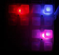
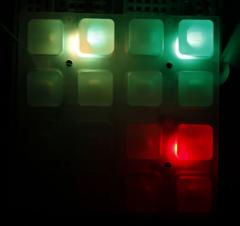
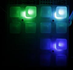
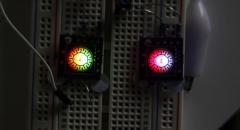
The blue+red version will even come out a bit cheaper as the LEDs are less expensive. But I'm with you: green-blue-cyan has the most balanced colour. I really like the red LEDs as they are deep and powerful but the mixing with green just doesn't work properly. Underneath the silicone buttons the light is quite diffused, I didn't notice any pain here. The biggest outlay for me will be the case (>$500) as I will have to order one to check everything works. After that the price will be lower but I hope we can agree on one design/finish and I will preferentially sell PCBs to those who will buy a case too. When you say "contrast case" were you thinking of another case design, or a combined front panel? Anodised perhaps? If so there might be a way to get different finishes (e.g. black) but this would be an add on. I'm happy to discuss other styles, maybe people prefer a flatter box? First of all I will get the PCB working and we can go on from there. -
Full 16x16+X BLM with silicone buttons, matching case. Interested?
latigid on replied to latigid on's topic in MIDIbox BLM
Cool, four-and-a-maybe is a good start! You'll have to check with TK on this one, basically you have some CC control over parameters on the SEQ. I did ask but it will be a development feature once people have the hardware. Joystick feature-creep! There is a bit of space (about 30 mm square) on the bottom right corner of the panel but none on the PCB. The sparkfun/ PS2 thumbstick might fit but I can't find accurate dimensions for it. The panel to PCB spacing is only 5 mm, so I think this is a no-go sorry. Great! C'mon Hawke, Moar ghear right? You could say you picked it up from an ESA flohmarkt? But thanks for the support anyway. Let's get some built and we'll try to tempt you later :). I almost got a good deal on LEDs from Aliexpress but the shipping cost and time doesn't make it worth it. I'm not sure if it's a good idea to order from Mouser at the 1000 piece price break before the concept is proven, otherwise I'd have a lot of spares on my hands... What's the general consensus? Green-blue-cyan for the moment? Or are there some attached to red-blue-pink?
-
Full 16x16+X BLM with silicone buttons, matching case. Interested?
latigid on replied to latigid on's topic in MIDIbox BLM
Altitude, Phatline, duly noted and many thanks! Lamouette, merci à toi aussi. The LED brightness is between 100-300 mcd. I was running these at about 8 mA while the peak is 20 mA so there is a little bit of room with current limiting. Maybe the duty cycle could also be altered. At least without the silicone pads they are painful to look at :cool: . I'm not sure about direct sunlight visibility but I can try if it's nice tomorrow :). The brightness is good in a naturally lit room in any case. For data the idea is to use an 8-pin DIN connector. If you have the Quad IIC module installed in your SEQ you connect the BLM for bi-directional MIDI and power (see here). The connector is a nice Amphenol pannel mount but the male plugs are a bit pricey at about $9 each. If anyone knows of a cheap supply of pre-made cables we could drop the cost slightly. I'll aim to get the PCB layout proofed and ordered this weekend. -
Cool beats! :flowers:
-
Full 16x16+X BLM with silicone buttons, matching case. Interested?
latigid on replied to latigid on's topic in MIDIbox BLM
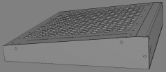
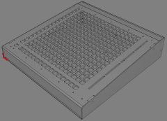
Case renders (too many images in first post): I’ve also come up with a case solution using 3.2 mm aluminium plus a spacer to align the button pads, which is cut out of acrylic. It was a bit of a headache to find the right combinations of spacer height and panel thickness but I think 3.2 mm should be strong enough with all of the holes. The case includes self-clinching blind studs to fix the PCB to the front panel, standoffs on the bottom for both r2/r3 and r4 Core8 modules, a rear cutout for a DIN8 plug and rubber feet. I checked but didn’t see any other truly suitable commercially available enclosures. Another option is a case by Heidenreich. Keep in mind the 289 holes dictate a fairly stiff metal should be used. -
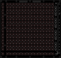
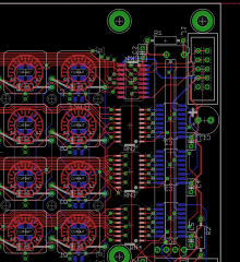
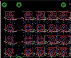
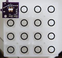
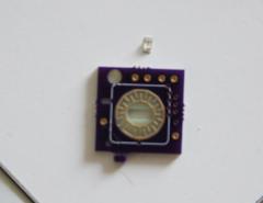
I’ve spent quite a bit of time in designing a full 16x16+X BLM. It’s using the ADAfruit silicone pads and rear-mount LEDs. First I tested the LED concept with OSHpark boards. I tried red, green (not yellowy green), yellow and blue, and all of their combinations for the “third colour.†Although I was happy with the illumination for red and green separately, their mixing is unfortunately quite poor. What does work however is red+blue = pink and green + blue = cyan/white. The latter is my pick to use in BLMs. Yellow LEDs looked okay but only the combination with red was decent, albeit not very different in colour. I have a 300 mm wide 4-layer PCB made up that additionally incorporates all 5 SCALAR modules and 4 sliders for analogue action. The sliders are Bourns PTL meaning there’s one LED in each too! Not just for bling, these are some of the lowest profile available. One concern I have is that the SC trace changes layer quite often (clock is best when it doesn’t go through vias), although I’ve routed everything in a chain like TK suggests. If you have any experience with this, please share! But if the MBHP_DOUT and past standalone SCALAR boards work with their routing, then potentially this should too. I kept one layer as a ground plane but used each of the other three for routing. Too hard with all of the cutouts and the top layer predominately un-masked copper. Current sinks are BC818 transistors (SOT23), shift registers are SOIC16, and resistor arrays are a wider version of this. LEDs are approximately 1206 size. I have through-hole 1N4148 diodes which will need to be trimmed short and soldered from the rear. Also there are leaded 100nF decoupling caps, which is again not best design practice but I can change them if anyone objects. I figure that you have to place a via in any case… I put in 0604 RC termination footprints in case this is necessary. The costs are reasonably high. I calculate a finished unit might be as much as $800, with the machined case being around $350 and a $250 Mouser order, mostly for LEDs. The button pads, PCB and spacer make up the rest. So… my question is: who would like to build one? It would be really helpful if you could indicate by replying below. The more interest, the cheaper it will be for everyone. Of course I will get one unit working before going further. It’s just good at this stage to test the water.
-
© 2015 latigid on
-
© 2015 latigid on
-
© 2015 latigid on
-
© 2015 latigid on
-

© 2015 latigid on
-
© 2015 latigid on
-
© 2015 latigid on
-
© 2015 latigid on
-
© 2015 latigid on
-
© 2015 latigid on
-
© 2015 latigid on
-
Hey, What's the motivation for this one? The original is 80x80 mm so your's isn't that much smaller. Do you have a particular space constraint? I don't use Altium so I can't comment on the PCB design, but I'd suggest: * Through-hole electrolytic caps. SMD are a pain in the butt, perhaps better with a reflow oven but I'm dubious about DIY versions of these in terms of their temperature homogeneity. The trimmers also look like they'll be annoying to mount, and are less mechanically robust for the long term. * 2x5 DIL header for data. The original pinout is also incompatible with modern Cores. * Better clearance around mount holes. * Consideration of a new offset circuit that is truly switchable. Check some of my posts or Altitude's MAX525 SMT design.
-
The LC uses a TL072, fine to run this on +/- 15V. The only change would be to adjust R50 and R52 to make the offset trimming easier, but maybe it's fine as-is. Try it!
-
It's not clear what you have. When you say "a complete PSU instead of a transformer on its input" does this mean you have a 15 V plug pack of some sort? If so is it AC or DC? I think if you try to wire a 7812 and a 7912 in parallel you will have problems. Or if you've already got a regulated bipolar +/- 15 V PSU then that's fine to use for AOUT_NG without modification. Is it linear or switching? Linear will be better. Some more info or pictures will help to get the best advice for you.
