latigid on
-
Posts
2,524 -
Joined
-
Last visited
-
Days Won
149
Content Type
Profiles
Forums
Blogs
Gallery
Everything posted by latigid on
-

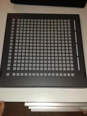
Full 16x16+X BLM with silicone buttons, matching case. Interested?
latigid on replied to latigid on's topic in MIDIbox BLM
The preferred way is with the BLM port on a quad IIC module. This combines MIDI in, MIDI out and power connections on a DIN8 socket. There's a matching DIN8 on the BLM case; I've wired up a DIL10 header to go to the miniCore board. You can also use a DIN MIDI port on the SEQ, just connect and define which one you use. This is how I've tested mine because I can't easily get a hold of the PCB mount DIN8 to complete the quad IIC. -
Alternative to LED encoder rings: illuminated red-green encoders?
latigid on replied to latigid on's topic in Design Concepts
Depends on how many encoders one wants to cram on a panel :) Is 16 enough? (Fairlightiii used 43 mm spacing on a 342 mm PCB) -
Alternative to LED encoder rings: illuminated red-green encoders?
latigid on replied to latigid on's topic in Design Concepts
For the programming I suppose there are benefits in avoiding matrix routing (also easier for PCB routing, just use separate DOUT pins for each LED). And for the space, couldn't we use Waldorf-style clear knobs? I imagine some room could be gained over the LRE8x2, even by staggering the encoders (i.e. offsetting a row horizontally). BTW, if someone would like to do the programming, I'm keen to do the PCB, maybe for a "Wilba-style" all-in-one MIDIbox CV v2. It might include 16 encoders with switches, CLCD, 4xGLCD and a few extra buttons. If not, maybe this would be a good place for me to start :). -
Looking for sammichSID control surface pcb, mine's broken.
latigid on replied to Pigsnoot's topic in Fleamarket
Post a photo? Maybe it can be salvaged with a few wires? -
BLM 16x16+X PCB and case order [CLOSED/waitlist]
latigid on replied to latigid on's topic in Bulk Orders
Please update the following table as appropriate: Name PCB BLM PCB miniCore Case Shift button M2 hardware 4xLED availability 9 9 - 12 9 20 latigid on 1 1 1 1 1 1 Total 1 1 1 1 1 1 -
This is a bulk order thread for the BLM I've designed. Please post here with the quantities you desire. I will leave the order open until Sunday July 26. Note that I will give preference to those ordering both the PCB and case as the main goal is to have a complete system at the most affordable price for all. The original concept is here: Here is a rundown of the costs in USD: PCBs: Main BLM PCB: 75 miniCore PCB: 4 Mouser components (available soon as shopping carts): BLM: 247.97 miniCore: 9.49 (excluding PIC, available from SmashTV) The main cost of the Mouser cart is LEDs. If groups wanted to order over 1000 pieces then savings of around $45 are possible. Also the red LEDs are somewhat cheaper. Buttons: 18 pieces of 4x4: 108, depending on where you order from. single shift button: 1 These are available from adafruit and various other sellers like flikto.de. There are discounts available, but one has to order over 99 pieces... 3 mm acrylic spacer from Formulor/Ponoko: ~55 depending on where you order from. Case, including shipping to you worldwide: 285 (>4 pieces) 250 (>9 pieces) I will have to add a few extra studs to increase stability, so it's possible that these might be a few dollars more. Hardware: M2 grub screw, washer and nut in stainless steel: 1 20xM3 washer and nut ~3 4xwhite square LEDs to fit Bourns sliders: 1 Shipping is ridiculous from here. I will post when next travelling to the EU Estimated cost: CH: 12 or pickup DE: 12 EU: 25 International: 28 Payment can be made by bank transfer or PayPal (with fees paid or 4% added for the latter)
-
Full 16x16+X BLM with silicone buttons, matching case. Interested?
latigid on replied to latigid on's topic in MIDIbox BLM
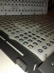
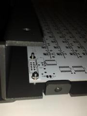
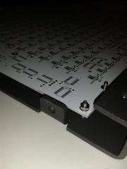
Case pictures: Update: Communication to miniCore working well I still have a few issues with MIDI IO 3, but it works fine through MIDI IO 1 Case looks fantastic and is perfectly strong enough. I believe that the top and bottom bend radii will increase the strength significantly. The grey powdercoat colour provides a nice contrast with the buttons. PCB flex is no problem in the centre and the north/south edges but a bit flimsy on the left edge. I should have included the blind studs here as they are barely noticeable, and will definitely for the final case. For mine I will find a different way to stabilise it. There are a few PCB errors and I think at this stage it's best to just go with new PCBs. I will start a new thread for confirming orders. -
© 2015 latigid on
-
© 2015 latigid on
-
© 2015 latigid on
-
© 2015 latigid on
-
Alternative to LED encoder rings: illuminated red-green encoders?
latigid on replied to latigid on's topic in Design Concepts
Good to hear that the encoders are nice! Indeed, the interface is there, but what is the implementation with a DOUT module? Looks like Duggle has experimented with PWM on DOUT: More recent one: -
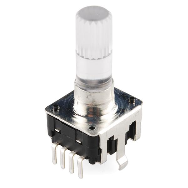
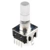
Just a quick concept with not too much thought behind it: LED rings are great but seem very clunky to implement. You either need a single board (Ã la Fairlightii) with through hole LEDs or surface mount, which introduces panel problems (i.e. one needs a transparent case). Or you design stackable daughter boards like FantomXR, a good idea but adds to the cost. An alternative might be to light the encoders directly. For example, Sparkfun have these encoders with a switch button and two common cathode LEDs (e.g. red+green). Currently $2.66-$2.95 depending on quantity. https://www.sparkfun.com/products/10596 I have to admit I don't have a lot to go on from the software side, but I imagine one could get some pretty intuitive colour mixing by changing the levels of each red and green LED. If we consider that there are usually 16 LEDs per ring, a possible 2 bit scheme could look like this. Green Red 0 0 OFF 1 0 green colours 2 0 3 0 3 1 orange colours 3 2 1 1 2 1 3 3 1 2 1 1 1 2 1 3 0 1 red colours 0 2 0 3 Of course it might be swapped around somewhat, but it's a general idea to start. Interested to know how this might work from the software side because I think for bling factor and hardware implementation it could be quite worthwhile. The colours also enable other possibilities, like a VU meter scheme, LFO phase, simple on/off switch or 4-state parameters etc.
-
Interesting concept, no filter input though?? Bah, I see it as I/O now...
-
There are other ways of randomising things, check out some of the FX or the loopback modes.
-
Still relevant I feel. Mostly for the BLM, but also for older Cores, to gain 4 MIDI outs or if you don't need/want the MIDI ins.
-
Sure, but is there another relevant thread for the quad IIC? I just wish you'd stuck with the original footprint :). Personally I've already bought the wrong part several times; I think RS might have also 'replaced' their 3-2-3 with a 1-4-3. In any case it would be good if any future PCB runs could have a dual footprint.
-
For anybody following, be careful on the pinout for the DIN8 socket. The 1-4-3 layout originally suggested is much more common now and Mouser's datasheet for 806-KCDX-8S-S2-PS is (at this time) incorrectly shown as 2-3-2 3-2-3. RS #491-049 looks okay, one has to buy 5 at least where I'm looking. It seems that Reichelt no longer stock DIN8 PCB mount...
-
+35 °C soldering!
-
Meanwhile, was there any progress with a new solution for gates? At some point I'd like to get a full SEQ breakout panel made and I wonder if I should implement space for 16 gate outs. (See previous page for a possible panel mock-up.) Best regards, Andy
-
This part seems a bit off to me: This is the main gripe with selling to potential newbies: by writing this you're passing the buck onto the people who remain active in this forum. It would be better for you to say something like "if you ever have problems, please contact me and I'll do what I can to help. Failing this there's a dedicated community at midibox.org, but you should have experience with DIY electronics or be prepared to take the initiative and learn."
-
For sure, the mixed LCDs represent a special case for MBCV. Just to keep on topic: the main issue with the GLCDs is that there's no good way to panel mount them (AFAIK). Encoders could be panel mounted if needed but we might need to come up with a solution to have everything on the same PCB. If there was a long carrier board with 45 degree mounting for the GLCDs there would need to be a way to fix it at the bottom. This wouldn't be a problem with your 8x1 boards as you say.
-
In my opinion, if you're not after the extra encoders/LED rings, CV inputs and scopes, then it would be better to design for the Core8 to fit in Eurorack. Of course you lose the USB connector... Meanwhile, I've ordered some slightly modified jack boards that breakout the CV and gate connections, provide an LED for gate and additionally switch the CV input or output range (depending whether an AIN or AOUT is connected). I managed to get the size down to 50x100 mm, thus it could fit into a modular system, if people wanted to go that route. I will design a case housing the MBSEQ, MBCV and a complete IO panel for both however. This way I can get a decent 5V PSU and a separate bipolar 12V. But I'm also interested in sneakthief's progress; are the new carrier boards for the LCDs and buttons implemented yet? Is the case solution a clear acrylic like Hawkeye's Programma or an opaque panel with windows? How are the various components' distances? Greets,
-
I was scratching my head a bit yesterday with this also: what would you like to do with the Programma? Is the idea definitely to use the LRE8x2 boards with the LCDs somehow stacked above? Or should the bullet be bitten, and a new encoder board designed (preferably one with better current sinks and perhaps SOIC chips and/or LEDs)? This way the LCDs could be mounted to the PCB which avoids all kinds of trouble. One thing is the fabs start to get quite pricey if you go over 300 mm board size. Could an option therefore be to design an LRE4x2 with integrated displays? The cost would then become quite a bit lower as the quantities increase. I certainly support your project but I don't think it's the MIDIbox I need right now . What I am interested in is an MBCV 2 which would use the same LCDs. I wonder then if there's a solution that would be applicable to both projects. Already it's gonna be a bit of a nightmare to try and arrange the LRE8x2, 4xGLCDs, 20x2CLCD, buttons and an encoder to the same panel height. It may even call for a single PCB akin to the Wilba SEQ. Sorry for the semi-off topicness!
-
Well, if the MD can send CCs from its control knobs which the SEQ records into a parameter layer... then we could be in business! But the implementation sounds very difficult, not to mention that this would quickly eat tracks, while the drum tracks have a limited number of parameter layers... Still it deserves further thought! Sorry for the thread hijack btw OP!