

jojjelito
-
Posts
1,483 -
Joined
-
Last visited
-
Days Won
10
Content Type
Profiles
Forums
Blogs
Gallery
Everything posted by jojjelito
-
Formulor - Medium gray transparent. I think it's Acrylic GS.
-
The LRE boards with pre-soldered SMD LEDs come with the slight baggage of having the LEDs almost flush with the PCB surface. On the other hand we have to contend with the height of the encoder body as well as that of the OLED sandwich. There's a good chance this too might look good, but until someone steps up with something based on those housed under an acrylic sheet we won't know for sure. The 3mm LEDs at least have a bit of lit body that rises up a few mm from the PCB. It could also look cool with rectangular LEDs, but if we used those it's no longer possible to fit the OLED in between. There's always these pesky trade-offs :) How about sending an email to fairlightiii? If he's incommunicado we'd have to recreate the whole shebang. FYI - I really really don't like Eagle - its ancient workflow totally frosts my balls. Maybe some recent version is better? :geek: Meanwhile, there are some interesting hardware issues to look at, plus mapping the controls for a few synths :frantics:
-
I'd like a pair of those too please. Thanks!
-
Yup. Keyed connectors for safety against plugging something in the wrong way are preferable. 2x3 or 1x6 or 1x7 with a gap doesn't matter if the connector sits so that it doesn't make the PCB larger. Keep the 2x3 connector block as it's easier to use with IDC flat cable that way. The only small issue is if someone believes it's an AVR ISP programmer port, but you can't be safe against everything :)
-
Ahh, gotcha! I've never been able to look past the AutoCAD 1980 interface horror of Eagle (well, that's my take on it) to get to those details so far :) I could maybe force myself to learn it, but there are modern alternatives out there that work better for me. If it fits, then by all means use it. Keyed connector: The 2x3 connector block gets keyed too if it sits in a shrouded connector:
-
That's a very clear layout! Isn't it possible to make it more compact by folding the flex cable so that it wraps around the PCB edge and gets connected on the bottom side of the PCB? Also, to save space it would be possible to use a 1x7 pin row with one pin missing so the the connection gets keyed. Imagine a board like this, but where the pins are located in a row below the screen and there are no dog ears with mounting holes:
-
I agree with Hawkeye. This is also a work in progress. Later on we will know more as there's a bit of work just mapping up the controls of various synth engines. :frantics: Another totally convenient use case might be support for generic USB keyboards if working with patch names. Or, we'll have to come up with some Xbox/PS3-type of keyboard list. I haven't the foggiest at this stage. Named preset lists for synths with expansion cards? Dunno either. Let's see where this all ends up as it slowly grows. :smile: You might argue the case for some special control element like a button bank for preset selection, or the use of absolute mechanical encoders like the nice 16-position Grayhill switch we know from the x0xb0x. It has a normal 4-bit binary output. Or, what about analog stuff like the 45mm LED sliders like those used by the TTSH ARP 2600 DIY clone? Would't they make a great envelope controller or organ drawbars? A bunch of LEDs, or the button/LED matrix from the MB-6582? Lots of synths have mod matrices. This has to be looked at later and can be placed in some box on the side if and when there's a need. I'm totally adding a joystick for that feeling of vectory. It kind of fits the Wavestation A/D and the Prophet VS. Lots of stuff could be mapped to its two axis. Also, inputs for foot pedals and switches would be nice. Anything that relies on these special control elements would take away from the generic nature of the MBProgramma. My hope would then be that external hardware elements are also linked to some settings that are shadowed in the normal system of banks and sub bank settings. This way they become shortcuts to various existing settings. Well, gotta hit the hay! Have a good one! Johan
-
Nice to hear! I can't speak for Hawkeye, but more LEDs and buttons can certainly be added. Some thought is needed -i.e. do we sprinkle them out here and there, or keep them around the lower display/SCS area or somewhere else? Obviously we can't make a dedicated controller such as the lovely JD-800 control surface. Another option would be a couple of blocks with 8LEDs and buttons on top/below to cycle up/down as well as a button next to every LED. If this sits on the side of an OLED we can select LFO 1-8, ENV 1-8, Waveforms going into a mixer, A block or blocks of harmonic levels, FM operators... However, Hawkeye has a lovely gray Plexiglas/acrylic overlay which it wouldn't be nice to have to scrap. We need to synchronize a little. Best, Johan
-
Ali Express link to the extant OLED choice: http://www.aliexpress.com/item/New-10x-3-3V-0-96-OLED-display-module-Arduino-compatible-128-64-White-Color-SSD1306/621502022.html There's a pinning diagram, a photo of the board as well as dimensions. Also, the SSD1306 data sheet gives the following: 4-wire SPI uses the following pins: D1: SDIN D0: SCLK CS#: CS# (labelled CS in the AliExpress data) D/C#: D/C# (DC) RES#: RES# (RES) plus of course: 3V3 GND So, just 7 things to connect, plus some things to strap. Better than all 16 pins.
-
There's a link in the MBProgramma thread to Aliexpress. However, it gives me a 500 code at the moment, there's either an issue here at work, or some web host is affected. Also, you can get some interesting data from the SSD1306 data sheet.
-
Well, I think that the cost savings are minimal at best. However, if you made a special PCB with pinpads in the middle of the whole show you could make it almost as small as the screen. But, it's a difficult endeavor. Also, that board would be a little thicker than today's solution and that's very critical too. The other attack vector is then the LRE board itself...
-
This means that even if we tried to shave off a few dollars of the MBProgramma OLEDs, they would still have a pin connector with 1 row of pins. There's currently no way to make them fit straight without being a little diagonal. But, it adds to the personality of it :pirate: Avast, ye scurvy dogs!
-
Here's an example of empty carrier PCBs on AliExpress: http://www.aliexpress.com/item/100PCS-LOT-0-96-inch-1-3-inch-OLED-adapter-plate-free-shipping/2031452713.html There are lots of variants. Better go for some facts-checking before I'll post a wiring diagram. Edit: I earlier assumed that 4-wire mode was SPI. Still think that's the case, but I'd better check the facts after work.
-
I saw that someone in China on Aliexpress had carrier PCBs you can buy. If those contain the necessary 2.8V power circuit they could be used. On the other hand, it shouldn't be impossible to work with those FPCs either. Then again, the MBProgramma application uses 4-wire mode. There has to be some variant of these displays with just the pins necessary for that.
-
Then again, remixed LRE boards with SMD shift registers, maybe even LED resistor arrays etc... A really bizarro adaptation would also be prepared for LED-lit encoders. Most of the pinning stays the same, add a few pins for the switch and the LED(s) of the encoder. As usual we only face two simple problems; time and money :tongue: For now, we substitute those with good ole elbow grease. Roll up your sleeves! Bonus points for the beer-drinking cat. It sounds like a real cat dude! :cat: Hang in there ilmenator!
-
Ahh. Olivier wrote about how he had a proto Ambika that wasn't through-hole at one point of time during its conception. You have nice stuff like the Audiothingies P6, the Preen FM2 etc built on minimal interfaces and MapleMini or similar CPU boards. A bigger VA would be a nice thing. I'd call it Vakov. The V is pronounced as an F in German, Dutch and Flemish :) Then again, I had ideas and plans for a simple poly based on Wavetables and a CPU timer driving some CEM3396. A DIY Evolver if you will. Your plans sounds like a Touch-screen Modulus! Ambitious and bold :) It could be a kick-ass synth.
-
Haha, yeah. It would make a killer MBsid 3, wouldn't it? You could also re-target it and make an Ambika with LED rings and some OLED parameter display action for instance. Those displays are just the ticket, but lacking a carrier PCB you might have to get a connector for that foil cable. That connector is likely to be a fine-pitch SMD so it's not that easy to work with. The fact that the seller advocates soldering the FPC onto the PCB... You have to do that right and there's a risk it becomes a brittle point of failure. OK, I know that's how it's bonded to the carrier PCB, but that's done with machines and probably inspected under a microscope. It's not a DIY-friendly solution. I get bad memories from the Chroma Polaris foil overlay :brr:
-
I added a few features to the Humanize function...
jojjelito replied to borfo's topic in MIDIbox SEQ
Definitely cool! Gotta try this out :) Thanks for coding. -
Some parts: OLEDs - we opted for something with a full set of pins, there are cheaper alternatives with reduced number of pins, i.e. SPI only. Those might save you some dollars. http://www.aliexpress.com/item/New-10x-3-3V-0-96-OLED-display-module-Arduino-compatible-128-64-White-Color-SSD1306/621502022.html Encoders are Alps EC12, 24 detents with switch: http://www.ebay.de/itm/15x-ALPS-EC12-Profi-Encoder-24fach-isoliert-mit-Taster-Automotive-kw-/291350442945?pt=Elektromechanische_Bauelemente&hash=item43d5d6f3c1 Green LEDs: http://www.ebay.de/itm/1000PCS-Diffused-LED-3MM-GREEN-COLOR-GREEN-LIGHT-Super-Bright-GOOD-QUALITY-/290928814710?pt=LH_DefaultDomain_0&hash=item43bcb56a76 Knobs: Alps, ask kristal= :smile: LED resistors: 47R For the SCS part: 6pcs standard MBSEQ tactile switches, TL-1100. If you're posh you can use Marquart, Digitast, ... 6pcs standard MBSEQ tactile switch caps :smile: ULN drivers are used with the LEDs of the LRE boards.
-
Well, when I got those I had this crazy, vague idea about a Nord Lead/Nord Modular-inspired control surface... Unfortunately, the rest is just work :frantics: I don't know if there will be more bulks, if the LRE boards will be available through Smash, or if the fab them yourself option will be available. Most data has been published as far as I know. PM Fairlightiii maybe?
-
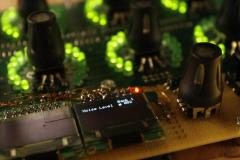
Well, this thing uses a few of the existing LEDring PCBs by Fairlightiii so I guess it could be racked if you really wanted to in your case. However, the PCBs are almost a wee bit too tall to fit in a 2U rack as they are 85.54mm tall. 2x44.5mm leaves very little margin, but you might be able to pull it it off. Peter has prototyped, and I'm in slow progress building it, a tabletop version. However, MIDIbox is modular, so you can mount these guys any way you see fit. I was going to leave it be until a bit later, but as times go by I'll start adding documentation to this thread, i.e what did we use, how is it interconnected, why did we build something instead of buying a controller, can you build me one for a school project... I'll start with something weird: Why Programma? Nobody knows fer sure :smile: Peter came up with it and it sounds like Brit slang for programmer. Then I realized that it's also the name of a really cool, classic programmable desktop calculator made by Olivetti c:a 1964. In a way it was a general computer and it was ahead of its time. I'm not sure this will be as groundbreaking, but it's as good a name as any :smile: OK, a few remarks before the questions start: The photo above shows an OLED that's twisted in a diamond shape. Why is that? Well, the OLED sits on a carrier PCB. I don't want to buy unbonded OLEDs and have to use special connectors. There's no room for the carrier PCB unless rotated. If this is offensive to your tastes, you can either move the OLEDs around as you like and sandwich them between the LEDring boards, but we like them to point out 4 different parameters. You could also re-spin the LED ring PCBs so that there's more room between the encoders and fab them at OSHpark or some similar place.Why don't you use 16mm encoders?Because we found smaller and cheap encoders with switches! You gotta love switches!Why so many OLEDs? Those are expensive!Because OLEDS! I like this programmer to be fairly interactive and to clearly show which control does what. Since MIDIbox supports hooking up a bunch of these why not? I want a nice box. If I only wanted cheap and something that does the job without fuss, I already have a BCR2000.Can you list components and where you got all of them?Yeah, later. I need to consult my PayPal and Ebay history, old PMs and such. Compiling all of that isn't something I'm going to do while at the office.OK, I'll be back. Toodles! Johan
-
Yarr! The SIDs sound really nice through the SSMs! Thanks for sharing it :) Johan
-
Nice one! Thanks for posting it :) Johan
-
 Yarr! This is shaping up to be a really nice MIDI controller!
- 1 comment
-
- 1
-

-
- MIDIbox NG
- LEDrings
- (and 1 more)
-
TK was sobering up so he got 4 fresh beers from me to start the Christmas Eve with :) Skål!