Janis1279
-
Posts
287 -
Joined
-
Last visited
-
Days Won
1
Content Type
Profiles
Forums
Blogs
Gallery
Everything posted by Janis1279
-
Please. clockbox_enhanced_v1c.rar
-
edit by nILS: Janis, please don't full quote. Are your 4-octave keyboards have a midi ? Then you can merge it, it's. As i understand from the some forum article, it is possible to mix sid pairs : core1 with the 6581, core2 with the 6582 etc. But then you need understand power supply and oscilator diferences . With the more sid's in your sound synthesizer the sound possibilities are greater. Regards, Janis
-
Installation problems for mios midibox 64
Janis1279 replied to damiano's topic in Testing/Troubleshooting
Hello, from your earlier post: ... "I wanted to create a MIDI interface on the basis of midibox 64, which serves to draw the scene for my management software lights I serve the switches that trigger midi notes, at most 50. I would use the switches momentary, but the function is a implemetare aceensione static, I'll explain: When I press a switch (momentary), the note to go on, I press a second time and back off the note. Obviously these switches must be related to LEDs, been displayed to the state of the note! .... This thing can be implemented simply by software? or do I use the flip flop configured as a bistable multivibrator, in order to perform the on-off! and then I will require an additional 10/12 momentary switches, which perform the function of momentary on-off notes, I explain: I press the switch, the note is on, leave the switch and the note to be off. third requirement. I manage, 12/15 against change, from flying to the value 0 127. then 4 / 5 of these, I would manage with rotary encoders, with dedicated LEDrings. and if possible other via potentiometers." ... I thinking, you need upload the midibox 64e application: http://ucapps.de/mio...ox64e_v2_2d.zip Regards, Janis -
Installation problems for mios midibox 64
Janis1279 replied to damiano's topic in Testing/Troubleshooting
Hello, In the HOWTOs part you can find and read : MIDI Interface Troubleshooting Guide May be you need at first to see your core midi input part: socket soldering places, optocoupler's direction on the 8-pin socket, etc. Regards, Janis -
Hi, May be this is useful: Link to the source code( not the latest revision, I think ) I found in Testing/Troubleshooting - Keyboard matrix 5 octaves, velocity,...by QBAS Basic key connections, as I understand, can find in: midiboxkb_-_using_a_c64_keyboard_as_input Regards, Janis
-
Hi, damiano, the first step is to build the MIDIO128 interface, the second step is to configure it with the MIDIO128 Tool. or may be I am wrong. I have not any project with the MIDIO128 interface yet. Regards, Janis
-
Welcome, damiano, Some infos about possibily button modes you can find in the MIDIbox64E Tutorial V2.x article under Midibox64E .You do not need to use the flip flop circuit to toggle the value . May be you can draw the simple schematic diagram of what you wish to build ? The basis of the midibox project is the Pic microcontroller based Core module (for the most of projects ). For the buttons and the encoders are used the DIN modules, for the leds ( ledrings ) - the DOUT modules. The potentiometers (> 8 pieces ) are connected to the AIN modules. Regards, Janis
-
Hi echo, If you have these buttons or similar, you need read more carrefully the note-schematic on the last page ( page 4 ) of the current data sheet . Regards, Janis JTP1230.pdf
-
Change modify DIN table on MBFM for button assignment
Janis1279 replied to Echopraxia's topic in MIDIbox FM
As I understand your wishes, you need to change only DIN SR 3,1, to 5,0, (or to 5,1, or to 5,2, etc. ) The other : SR2 pins are DOUT pins ;; --> 1*DIN/4*DOUT <-- pins of the 4 row select buttons ;; DIN SR/Pin, Row1 SR/Pin, Row2 SR/Pin, Row3 SR/Pin, Row4 SR/Pin DIO_M_ROW_ENTRY 5, 0, 2, 2, 2, 3, 2, 4, 2, 5 -
as an example. may be as here: http://forum.hauptwe...&t=3777&start=0 and as here: Line sensing circuit Filed under: Circuits — Greg Lipscomb ; Here is a simple circuit that can be used to detect a black line in a DIY line following robot. The R1 and R2, need to be picked so that the current or voltage across the LEDs do not go over the specifications of the components. You can use the simple equation V=I*R. V=voltage accross the LED, it could be the 5 volt power source, I is the current through the component, and it can be measured with a multimeter. R is the resistor value. Anyway, the LEDs are infrared, and here are the numbers for them. The infrared Emitter Diode was a Kingbright L53F3C. The Infrared Phototransistor (detector) was a Kingbright L53P3C.
-
Hi , Paul In my Midi Box Cores for LCD drivers I am using 2N2222 and 2N2222A transistors instead of BC337 without any problems. Regards, Janis
-
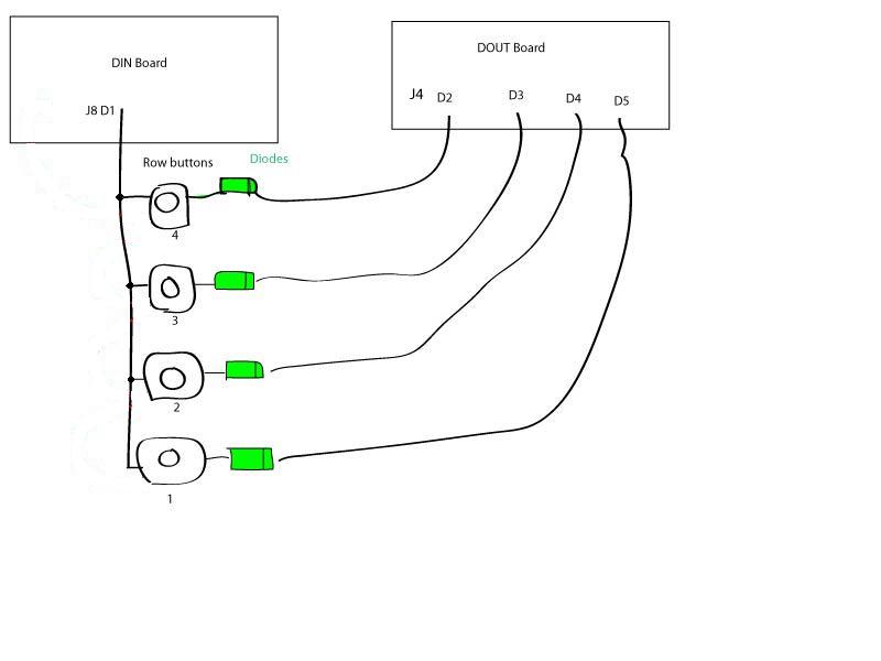
Every row button have a 1 NO contact.
-
These connections are correct. The better way to understand how the button matrix works, you need connect all 4x 6 buttons. Without leds, of course. Why ? Regards, Janis
-
The 4x row button diodes are additional diodes to DIN and DOUT diagrams. The Led button module part is custom maded and a picture not give a more clearer view , anyway. But these 4 diodes are included in my module. p.s. When I have interest to build or better understand for me any diagrams, schems etc. I am printing or drawing its,always. And then I look its many times if it needed . Regards, Janis
-
I may be wrong, but leds don't be wired for correct row buttons work. diodes of the DIN board are connected : R1 to the green coloured wire R1on the DOUT board, R2 to the green coloured wire R2 on the DOUT board etc. By default MB FM uses The third SR of DIN board for the row matrix buttons . Regards, Janis
-
В�ем приветики из Белару�и и парочка ?
Janis1279 replied to MrTorsionTorque's topic in Russian
Na skoruju ruku poiskom nasjol: no vozmozno, eto sovsem ne to. Po podsojedinenijam raznih datcjikov k MB platforme pripominaju user: audiocommander Udacji -
В�ем приветики из Белару�и и парочка ?
Janis1279 replied to MrTorsionTorque's topic in Russian
Privet, Toljko otnositeljno standartnogo MB zjeleza. V kacjestve centraljnogo modulja na ; PIC18F452 proce, Core po umolcjaniju imejet MIDI IN, MIDI OUT .Sjuda mozjno podkljucjitj GM5 module i budet USB gnezdo dlja PC. 2x DINX4 dolzno bitj dostatocno, no jesli ponadobitsja na upravlenije boljse vhodov, vozmoznosti rassjiritj imejetsja Dlja svetodiodov i odnoi 74HC595 mikruhoi budet dostatocjno. s uvazenijem, Janis -
Zdravstvui. A pazve priobresti GM5 mikruhu, platu ( jesli neobhodimo) i razsjiritj kolicestvo vhodov / vihodov mozjet okazatsja slozjneje cjem izobretatj svoi kontroler ? Ja ne uveren. http://www.midibox.org/dokuwiki/tk_gm5_bulkorder s uvazenijem, Janis
-
Hi echo Not any or... ! But are your leds are connected with it's longer legs to the DOUTX4 J4:D1,D0 and J5:D7,D6,D5,D4 pins ( in each column 4 x leds with longer pins connected together ). Regards, Janis
-

From the album: Janis1279
-

From the album: Janis1279
-

From the album: Janis1279
-

From the album: Janis1279
-
Hi, luke In the your MBHP_SID_V4.pdf file the 74HC595 SRs outs are connected to diferent pins of Sids, than I can saw in the Sid module and in the fnp-sid ( stereo sid ) schems. The first SR in this chain controls a data bus instead of addreses and the second SR controls a address bus instead of data. Is that realy workable without any software changes? sorry, may be I am wrong. Regards, Janis
-
Here : http://www.zimmers.net/anonftp/pub/cbm/schematics/computers/c64/250469-rev.A-right.gif you can find the 9VAC input : 9VAC1 and 9VAC2 pins. The 9VAC you can measure between 9VAC1 and a fuse F1 connection points. From your earlier posts, looks your 9VAC supply is OK ( you got a right reading of 11.82V on a Sid socket pin 28) . Regards, Janis