

ssp
-
Posts
659 -
Joined
-
Last visited
-
Days Won
4
Content Type
Profiles
Forums
Blogs
Gallery
Posts posted by ssp
-
-
-
New Edit! EOL
-
2 hours ago, Zam said:
Hello
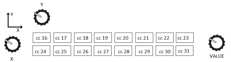
Don't know if you can do this without a script (NGR) to handle the 8 possible two CC toggle (equivalent to Y axis in a 2x8 pattern)
You can maybe simply with toggle scan X(16,17...23,24, 31,16....) and Y (16,24,17,25....31,16...) with 2 MAP
But in a strict "user friendly" interface I personally won't use two encoder to select data in a 2x8 matrix display (for a 8x8 OK...)
A single continuous scan will be as fast for only 16 slot (assuming you can go both direction, most distant data is only at 8 encoder tick) , OR you can use the encoder button to switch X/Y scan axis
Only two encoder, data and value
Best
Zam
it is actually 5 rows of 8 but i used 2 rows as an example before i start trying this. I am just curious if it is possible, I will have a play this evening and see where i get to.
I know that in thorstens blofeld files that there is the meta , bank and cond label used. i could alter this slightly but its the #cc as well.
will see what happens tonight
-
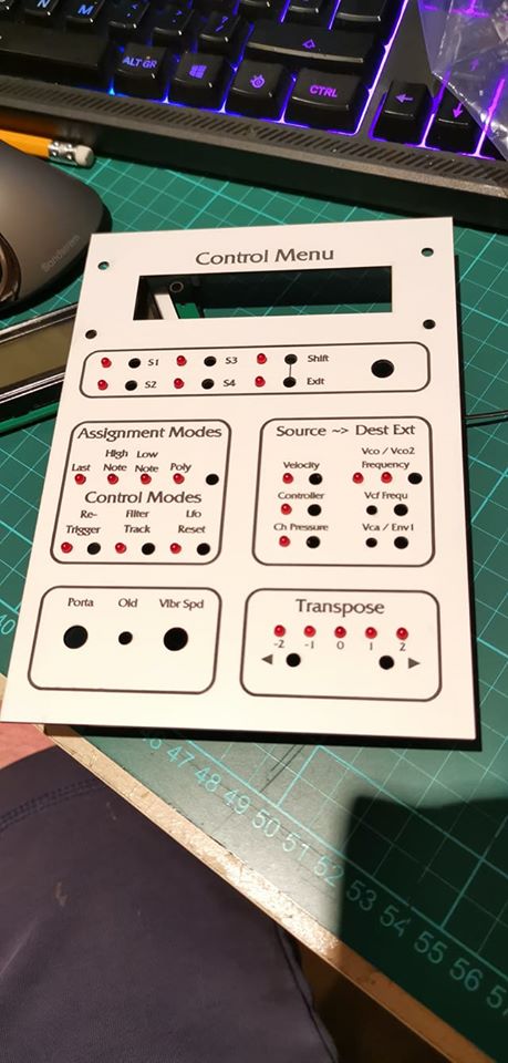
panel test day, checking fitment on led's and tact switches, then the pcb.

-
I have been playing with banks and cond labels again today all went well. I was pondering something though.
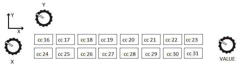
If i have a series of values i want to control from 3 knobs, so there are two lines of values, and 8 on each line, what i want to do to reduce the amount of encoders is have one for moving in the y direction between line 1 and line 2, then one to move in the "x" direction to step between 1 to 8 in the line, then a final encoder to change the value of the selcted cc#.
in a basic explanation (not real code!!)
Y= enc_1 if<64 line=1
Y= enc_1 if<127 line=2X= enc_2 if<10 cc16
X= enc_2 if<20 cc17
X= enc_2 if<30 cc18
X= enc_2 if<40 cc18Value= enc_3 type=CC ......... this encoder would have to change its code on each movement over x&y so cc=16, cc=17,cc=18 etc.
Is it possible to do this in the .ngc?
-
1: Is it strange that all i could do all week was think about finishing work and getting on with starting to learn the mios32 code now i have gone through the .ngc code.
2: Is it also strange that i was looking forward to various components arriving today and gleefully picking them up from the delivery box after work
3: Refer to 1 & 2 EVENT_UNDERSTOOD id= 1 type=command CMD=1 range= 0:127 lcd_pos=1:1:1 label="^DoThis "
COND_LABEL DoThis
COND <64 "Read 1&2"
COND <127 "Goto 4: "
COND_ELSE "--------"4: Great success you are officially a midiboxer geek and should be proud ;) now refer to 1 & 2 but in C#
-
looking here as well
MIOS32 Tutorial #017: A simple Sequencer
Sequencer
---------The BPM generator can be used in MIDI Clock Master and Slave mode with
a definable resolution, which can optionally be (much) higher than the
common MIDI clock resolution. It it configured for Auto mode, which means,
that it will generate an internal clock by default (Master), and synchronize
to an extern clock once the appr. MIDI clock events are received (Slave).
In slave mode, the incoming clock is multiplied depending on the defined PPQN
(pulses per quarter note).The MIDI event scheduler queues MIDI events which should be played at
a given MIDI clock tick. The approach has the big advantage, that
events can be pre-generated, eg. to bridge the time while loading new
pattern(s) from a SD Card, or to generate effects like MIDI Echo (very
simple, just put the note multiple times into the queue with different
bpm_tick values).
The advantage of using the MIDI clock as time base instead of an absolute
time is, that the sequencer is even in synch if the tempo is changedwhile unplayed events are in the queue.
This here "The MIDI event scheduler queues MIDI events which should be played at a given MIDI clock tick" makes me think that this is the way to go.
So now i gotta start learning C'???... lol
And i am also looking at the arpeggiator tutorials, this is all way over my head but i am reading through things, if anyone has anything else i should think of looking at let me know.
-
With some advice from antichambre I have taken a look at the github: https://github.com/midibox/mios32/blob/feature/usb_hid/modules/sequencer/seq_bpm.h
i noticed that it has the ability to accept bpm clock and be "clocked"
However this is not an .ngc file and I suck big time at C' in any form.
I have got the handle on most of the .ngc format now and would like to somehow make this work in there.
i understand that there are 24 pulse per quater note so anything slaved knows a quater has passed after 24ppqn. sending 0xF8 24 times.
So if each led has a sysex recieve of 0xF8 x 24 then the 25th steps to the next led etc would that work?
This is a whole new thing to learn but I am game to try it out.
-
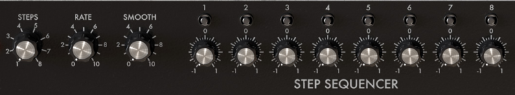
Im making a arturia mini filter replica controller and it has an 8 step sequencer that steps through 8 leds. this is switched by an 8 way rotary switch (STEPS) that has a value defined map.
The rotary switch defines the steps as the plugin does so if switched to 3 then only 3 steps are active and only the first 3 leds step 1-3.
If i were to use midi clock for this is it possible?, so the midi clock is forwarded to drive the 8 leds but they are defined by the rotary switch 1 through to 8 leds in use for the steps
so in effect the midi clock is always sent to the leds but the ones lit up at any time are set by the steps rotary switch.
I have everything else working, Maps, Range values and radio buttons, the steps knob works fine using my 8 position single pole rotary switch, and i am reading up on midi clock code at the moment.
thanks
-
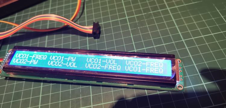
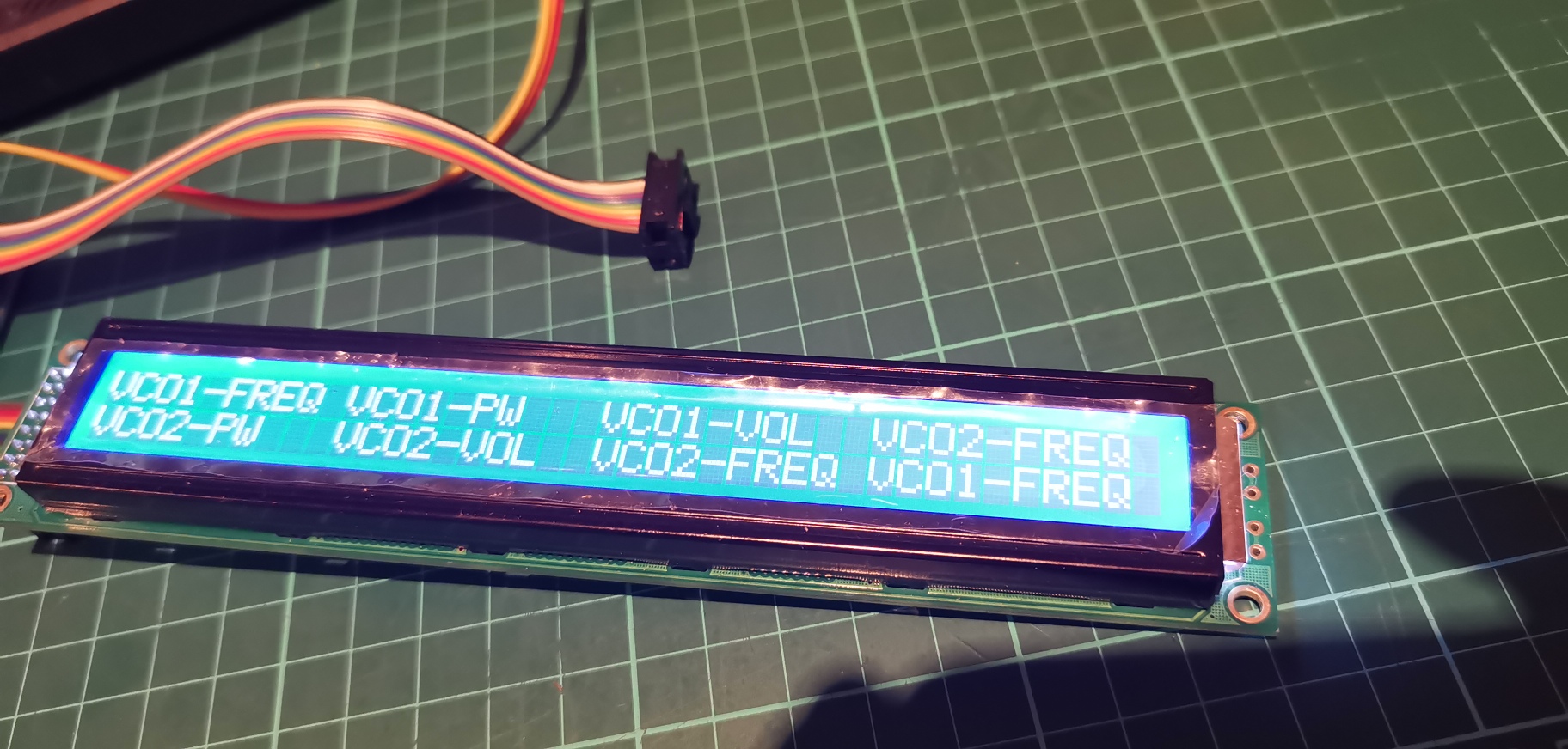
Had a little fun checking this out tonight, all working fine, I applied 8 enocders to various functions and then gave each label 10 characters on the lcd top and bottom row.
1. you define the amount of max characters by the spaces between the ".........." commas. For example if i put "VCO1 FILT " there are 9 characters and a single blank space. The next free character is 11
The spacing is then on a 40x2 display:
pos 1= 1:1:1 pos 2= 1:11:1 pos 3=1:21:1 pos 4=1:31:1
pos 5= 1:1:2 pos 6= 1:11:2 pos 7=1:21:2 pos 8=1:31:2For the COND_LABEL is used Dp1
so I wrote this to test
RESET_HW
# 40x2 10 character per 8 encoder test
ENC n= 1 sr=1 pins=0:1 type=detented3
EVENT_ENC id= 1 fwd_to_lcd=1 type=CC cc=16 range= 0:127 lcd_pos=1:1:1 label="^Dp1"
ENC n= 2 sr=1 pins=2:3 type=detented3
EVENT_ENC id= 2 fwd_to_lcd=1 type=CC cc=17 range= 0:127 lcd_pos=1:11:1 label="^Dp2"
ENC n= 3 sr=1 pins=4:5 type=detented3
EVENT_ENC id= 3 fwd_to_lcd=1 type=CC cc=18 range= 0:127 lcd_pos=1:21:1 label="^Dp3"
ENC n= 4 sr=1 pins=6:7 type=detented3
EVENT_ENC id= 4 fwd_to_lcd=1 type=CC cc=19 range= 0:127 lcd_pos=1:31:1 label="^Dp4"
ENC n= 5 sr=1 pins=0:1 type=detented3
EVENT_ENC id= 5 fwd_to_lcd=1 type=CC cc=20 range= 0:127 lcd_pos=1:1:2 label="^Dp5"
ENC n= 6 sr=1 pins=2:3 type=detented3
EVENT_ENC id= 6 fwd_to_lcd=1 type=CC cc=21 range= 0:127 lcd_pos=1:11:2 label="^Dp6"
ENC n= 7 sr=1 pins=4:5 type=detented3
EVENT_ENC id= 7 fwd_to_lcd=1 type=CC cc=22 range= 0:127 lcd_pos=1:21:2 label="^Dp7"
ENC n= 8 sr=1 pins=6:7 type=detented3
EVENT_ENC id= 8 fwd_to_lcd=1 type=CC cc=23 range= 0:127 lcd_pos=1:31:2 label="^Dp8"then there were the .NGL conditional labels in thier own tables from Dp1 to Dp8, I was really pleased it all worked first time and did what I wanted it to.
Going to play with banks again tomorrow and see if how i can implement that in as well.
-
Just now, jjonas said:
I think what's limited to 8 characters is the label variable (like ^destpane), not the actual string that's displayed on the LCD. In your example above you have strings that are more than 8 characters ("VCO1 FREQ" has 9 characters), and in fact you're not limited to 8 characters with the "VCO1 FREQ" style texts you want to show on the LCD. The variable length in characters (^destpane) and the string length in characters ("VCO1 frequency") are not related, so you can have short variable names and long strings for them.
Ah got it. i will change the the label variable to a abbreviated syntax instead, i can define my own syntax list then in the .ngl file and reference that.
Thanks again.
-
2 hours ago, jjonas said:
I ran into this a while ago. From the docs for NGL:
I didnt see this, thanks for the heads up on this jjonas, most appreciated!! it would be nice though as its a 2x40 and im using 8 encoders to be able to balance this out to 10 max characters per label. because you can then reduce it per your needs.
I wonder if this is something that Thorsten could implement ? where you can set your max characters in the .ngl file
-
Just sat working on a conditional label test and something wierd is happening.
I made two files test.ngc and test.ngl with one encoder attached
in the .ngc
RESET_HW
# this command is part of a .NGC file:
ENC n= 1 sr=1 pins=0:1 type=detented3
EVENT_ENC id= 1 type=CC cc=16 range= 0:127 lcd_pos=1:1:1 label="^Destpanel "
in the .ngl
COND_LABEL Destpanel
COND =0 "VCO1 FREQ"
COND =1 "VCO1 PW "
COND =2 "VCO1 VOL "
COND =3 "VCO2 FREQ"
COND =4 "VCO2 PW "
COND =5 "VCO2 VOL "
COND_ELSE "--------"On the 2x40 display all i get in the first line character is the "l" nothing else however, If i change ^Destpanel to just ^Dest then it shows VCO1 FREQ on the lcd. Why if i put the full ^destpanel am i getting the leter L instead?
It seems it only likes 8 characters, by removing 1 letter on each ^Destpanel to ^Destpane it works.
Is there an 8 character limit on the "Cond_Label" title name? if so can this be changed anywhere?
-
I have had to admit defeat on the NRPN's tonight and have msg'd Thorsten for some advice/help. the latest rev is great for the negatives etc, but its the dual commands i am stuck with and working out the values for nrpn and lsb msb etc. Crazy math frying my brain.
-
happy face this evening, needed to test some controls on a plugin and i just sat and wrote the code straight in and it worked first time, really happy guy!
-
This evening I continued playing with the .NCG code and the various conditional labels code and the assignments in the .NGC file.
Using Thorstens Blofeld templates i altered a few basic things to try them out.1. The scs encoder was not changing the bank when turned, as i dont have a blofeld to connect it too so my solution was to change a little code
I changed
enc_emu_id=2000 to enc_emu_id=2000 type=detented2 and I also hashed out this line as i didn't need it. #EVENT_LED id=2000 fwd_to_lcd=1 lcd_pos=1:1:1 label="^bank"
I was now able to change the bank.I also change a few other sections of code and encoder id's to see what would happen if linked to a second din. All has worked and I now have a good understanding of the use of conditional labels, banks and values.
Also the use of the meta command here in this string: EVENT_ENC id=2000 type=Meta meta=SetBank range=1:5.The .NGC commands and syntax are becoming more clear to me everyday now.
My next challenge is learning NRPN's and applying them to negative values a feature in the latest update. I have also played with the -64..0..+64 today as well.
What I have found helpful is printing out all the manuals, and having them to read when not on the computer, I like to mark things up as I go.
-
Had a really good evening learning the code structure for the condition labels, I made a new test .ngc and .ngl file and wrote a small section of code in and it all worked.
I was able to set up a set of conditional lables and also banks and set values for triggering the different lables on the press of a button or an ecoder or pot.
forwarding then to an oled or clcd of choice and also forwarding the value to an lcd matric (7 segment 3 digit display)
Some of the plug-ins i am building my controllers for have in thier gui small 1x6 and 1x8 virtual clcds so i can now replicate them in my hardware and not rely on a recieved input to show them.
-
Edit: just found something so i will re-update this shortly.
-
Lets carry on here:
I am ordering a couple of small 6x1 and 8x1 clds tomorrow.
Edit: I remembered the use of conditions from a previous post, reading up on this tomorrow and will give it a shot ;)
Lets carry on here:
I am ordering a couple of small 6x1 and 8x1 clds tomorrow.
Edit: I remembered the use of conditions from a previous post, reading up on this tomorrow and will give it a shot ;)
COND
CONDitional labels are the most powerful purpose of global label definitions - they allow to output different strings based on the EVENT value!
Following example demonstrates the purpose pretty nicely:
COND_LABEL fil_type
COND =0    "Bypass   "
COND =1    "LP 24dB  "
COND =2    "LP 12dB  "
COND =3    "BP 24dB  "
COND =4    "BP 12dB  "
COND =5    "HP 24dB  "
COND =6    "HP 12dB  "
COND =7    "Notch24dB"
COND =8    "Notch12dB"
COND =9    "Comb+    "
COND =10   "Comb-    "
COND =11   "PPG LP   "
COND_ELSE  "Type %3d "
An EVENT_* command can use it this way:
# this command is part of a .NGC file:
EVENT_ENC id=1  type=CC cc=16  lcd_pos=1:1:1 label="Filter Type: ^fil_type"
So: each value can be named, but it's also possible to define value ranges at which a string should be taken, such as:
COND_LABEL test1
COND =0   "Val is 000   %3d"
COND =1   "Val is 001   %3d"
COND =2   "Val is 002   %3d"
COND =3   "Val is 003   %3d"
COND <20  "Val is <20   %3d"
COND <=40 "Val is <=40  %3d"
COND_ELSE "else cond.   %3d"
Looking at this i understand the upper and lower condition tables, would you use the two tables individually or would they be combined in one string?
How would i implement this? would you have both condition tables one with labels and the other with the Val statements? or would you make a string with the label name and val syntax combined?
The COND =0 "Val is 000 %3d" I understand for the condition =0 the value is "000" this will display the label name set to this condition "id", in the table above this is "Bypass"
if the "Val is 001" then Cond -1 "LP 24db" becomes active.
both tables seperate or a combined string?
Thanks
-
Ok all is working i made a couple of mistakes in the code, duplicated #cc etc. But all is looking good now. I read up some more and can connect upto 8 doutx4 so that is great, now i just need to order some more doutx4 boards.
My Plan is now to condense this thread into a more useful one or make a blog and edit out everything that is duplicated or un-needed.
corrected code working over two doutx4, this has allowed me to learn and test the Dout_Matrix configuration on the MB_NG.
RESET_HW
LCD "%CLED Digit Demo"
# HW definitions for "Common Cathode" Digits
DOUT_MATRIX n=1 rows=8 sr_dout_r1=1 inverted_row=0 mirrored_row=0 sr_dout_sel1=2 inverted_sel=0
DOUT_MATRIX n=2 rows=8 sr_dout_r1=3 inverted_row=0 mirrored_row=0 sr_dout_sel1=4 inverted_sel=0
DOUT_MATRIX n=3 rows=8 sr_dout_r1=5 inverted_row=0 mirrored_row=0 sr_dout_sel1=6 inverted_sel=0
DOUT_MATRIX n=4 rows=8 sr_dout_r1=7 inverted_row=0 mirrored_row=0 sr_dout_sel1=8 inverted_sel=0
# these can be changed for each 3 digits to test connectivity
ENC n= 1 sr=1 pins=0:1 type=non_detented
ENC n= 2 sr=1 pins=2:3 type=non_detentedEVENT_ENC id=1 fwd_id=LED_MATRIX:1 type=CC chn= 1 cc= 16
EVENT_ENC id=2 fwd_id=LED_MATRIX:4 type=CC chn= 1 cc= 17
# First Value (3 digits) received via CC#16
EVENT_LED_MATRIX id=1 fwd_id=LED_MATRIX:2 led_matrix_pattern=Digit1 fwd_to_lcd=1 type=CC chn= 1 cc= 16 lcd_pos=1:1:2 label="1:%3d%B"
EVENT_LED_MATRIX id=2 fwd_id=LED_MATRIX:3 led_matrix_pattern=Digit2
EVENT_LED_MATRIX id=3 led_matrix_pattern=Digit3# Second Value (3 digits) received via CC#17
EVENT_LED_MATRIX id=4 fwd_id=LED_MATRIX:5 led_matrix_pattern=Digit1 fwd_to_lcd=1 type=CC chn= 1 cc= 17 lcd_pos=1:1:2 label="2:%3d%B"
EVENT_LED_MATRIX id=5 fwd_id=LED_MATRIX:6 led_matrix_pattern=Digit2
EVENT_LED_MATRIX id=6 led_matrix_pattern=Digit3# Third Value (3 digits) received via CC#18
EVENT_LED_MATRIX id=17 fwd_id=LED_MATRIX:18 led_matrix_pattern=Digit1 fwd_to_lcd=1 type=CC chn= 1 cc= 18 lcd_pos=1:1:2 label="3:%3d%B"
EVENT_LED_MATRIX id=18 fwd_id=LED_MATRIX:19 led_matrix_pattern=Digit2
EVENT_LED_MATRIX id=19 led_matrix_pattern=Digit3# Fourth Value (3 digits) received via CC#19
EVENT_LED_MATRIX id=20 fwd_id=LED_MATRIX:21 led_matrix_pattern=Digit1 fwd_to_lcd=1 type=CC chn= 1 cc= 19 lcd_pos=1:1:2 label="4:%3d%B"
EVENT_LED_MATRIX id=21 fwd_id=LED_MATRIX:22 led_matrix_pattern=Digit2
EVENT_LED_MATRIX id=22 led_matrix_pattern=Digit3# Fifth Value (3 digits) received via CC#20 (this is to test the first row on the second dout pcb)
EVENT_LED_MATRIX id=33 fwd_id=LED_MATRIX:34 led_matrix_pattern=Digit1 fwd_to_lcd=1 type=CC chn= 1 cc= 20 lcd_pos=1:1:2 label="5:%3d%B"
EVENT_LED_MATRIX id=34 fwd_id=LED_MATRIX:35 led_matrix_pattern=Digit2
EVENT_LED_MATRIX id=35 led_matrix_pattern=Digit3# Sixth Value (3 digits) received via CC#21 (this is to test the first row on the second dout pcb)
EVENT_LED_MATRIX id=36 fwd_id=LED_MATRIX:37 led_matrix_pattern=Digit1 fwd_to_lcd=1 type=CC chn= 1 cc= 21 lcd_pos=1:1:2 label="6:%3d%B"
EVENT_LED_MATRIX id=37 fwd_id=LED_MATRIX:38 led_matrix_pattern=Digit2
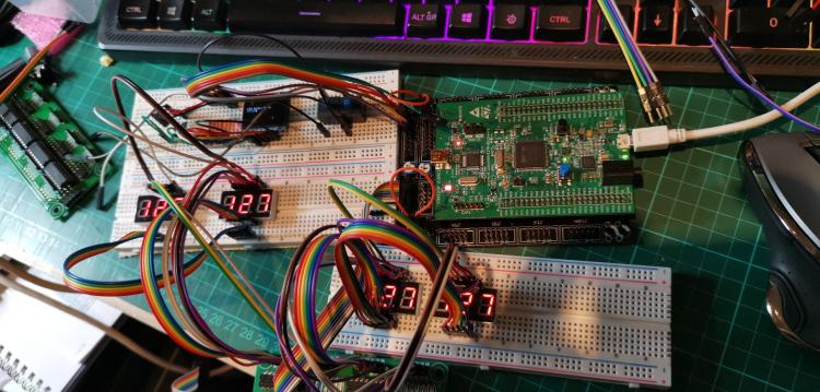
EVENT_LED_MATRIX id=38 led_matrix_pattern=Digit3 -
second dout connected digits showing on first display but not second. getting there.
-
14 hours ago, latigid on said:
I have got 4 working on the one DOUT but none on the second. Wierd.
-
the first two 3 digits on cc 16 and cc17 on the first dout work fine, the second dout is not working.. cant figure out why, all new wires and another new dout pcb as well.
-
ok ran the code, it didnt work, will have to look into this a bit more.
is this correct?
# Control 5x3 LED Digits to output 7bit valuesRESET_HW
LCD "%CLED Digit Demo"
# HW definitions for "Common Cathode" Digits
DOUT_MATRIX n=1 rows=8 sr_dout_r1=1 inverted_row=0 mirrored_row=0 sr_dout_sel1=2 inverted_sel=0
DOUT_MATRIX n=2 rows=8 sr_dout_r1=3 inverted_row=0 mirrored_row=0 sr_dout_sel1=4 inverted_sel=0
DOUT_MATRIX n=3 rows=8 sr_dout_r1=5 inverted_row=0 mirrored_row=0 sr_dout_sel1=6 inverted_sel=0
DOUT_MATRIX n=4 rows=8 sr_dout_r1=7 inverted_row=0 mirrored_row=0 sr_dout_sel1=8 inverted_sel=0# these can be changed for each 3 digits to test connectivity
ENC n= 1 sr=1 pins=0:1 type=non_detented
ENC n= 2 sr=1 pins=2:3 type=non_detentedEVENT_ENC id=1 fwd_id=LED_MATRIX:1 type=CC chn= 1 cc= 16
EVENT_ENC id=2 fwd_id=LED_MATRIX:4 type=CC chn= 1 cc= 17
# First Value (3 digits) received via CC#16
EVENT_LED_MATRIX id=1 fwd_id=LED_MATRIX:2 led_matrix_pattern=Digit1 fwd_to_lcd=1 type=CC chn= 1 cc= 16 lcd_pos=1:1:2 label="1:%3d%B"
EVENT_LED_MATRIX id=2 fwd_id=LED_MATRIX:3 led_matrix_pattern=Digit2
EVENT_LED_MATRIX id=3 led_matrix_pattern=Digit3# Second Value (3 digits) received via CC#17
EVENT_LED_MATRIX id=4 fwd_id=LED_MATRIX:5 led_matrix_pattern=Digit1 fwd_to_lcd=1 type=CC chn= 1 cc= 17 lcd_pos=1:1:2 label="2:%3d%B"
EVENT_LED_MATRIX id=5 fwd_id=LED_MATRIX:6 led_matrix_pattern=Digit2
EVENT_LED_MATRIX id=6 led_matrix_pattern=Digit3# Third Value (3 digits) received via CC#18
EVENT_LED_MATRIX id=17 fwd_id=LED_MATRIX:18 led_matrix_pattern=Digit1 fwd_to_lcd=1 type=CC chn= 1 cc= 18 lcd_pos=1:1:2 label="3:%3d%B"
EVENT_LED_MATRIX id=18 fwd_id=LED_MATRIX:19 led_matrix_pattern=Digit2
EVENT_LED_MATRIX id=19 led_matrix_pattern=Digit3# Fourth Value (3 digits) received via CC#19
EVENT_LED_MATRIX id=20 fwd_id=LED_MATRIX:21 led_matrix_pattern=Digit1 fwd_to_lcd=1 type=CC chn= 1 cc= 19 lcd_pos=1:1:2 label="4:%3d%B"
EVENT_LED_MATRIX id=21 fwd_id=LED_MATRIX:22 led_matrix_pattern=Digit2
EVENT_LED_MATRIX id=22 led_matrix_pattern=Digit3# Fifth Value (3 digits) received via CC#20 (this is to test the first row on the second dout pcb)
EVENT_LED_MATRIX id=33 fwd_id=LED_MATRIX:34 led_matrix_pattern=Digit1 fwd_to_lcd=1 type=CC chn= 1 cc= 19 lcd_pos=1:1:2 label="4:%3d%B"
EVENT_LED_MATRIX id=34 fwd_id=LED_MATRIX:35 led_matrix_pattern=Digit2
EVENT_LED_MATRIX id=35 led_matrix_pattern=Digit3


multiple Clcd's
in MIDIbox NG
Posted · Edited by ssp
With a nudge in the right direction from thorsten i managed to get this working today to a certain extent.
Using senders and maps i have got it working however the 128bit for encoders is the problem.
I did see that there is a resolution setting for pots, so perhaps i can edit this to my advantage, I am just going to build my ainser64 board and give it a try. using this section of the manual
MAP<n>/HWORDI Applies linear interpolation between data points. Up to 64 datapoints can be specified, the value range is -16384..16383 (16bit).
Example: