

ssp
-
Posts
659 -
Joined
-
Last visited
-
Days Won
4
Content Type
Profiles
Forums
Blogs
Gallery
Posts posted by ssp
-
-
Thorsten i am reading Johns "Known Issues" section on the custom fonts/ Bars section. Any thoughts on this issues he had? see if this is solveable? I can add this to my wiki documentation and reference johns when I am ready.
Thanks
PS: Happy New year!!
-
Had a good evening working on this, everything i have run through on first steps has worked. I have a din and dout hooked up led's are lighting up as they should with the set button presses etc.
The Oled display is working as it should off to have a read now and figure a few things out.
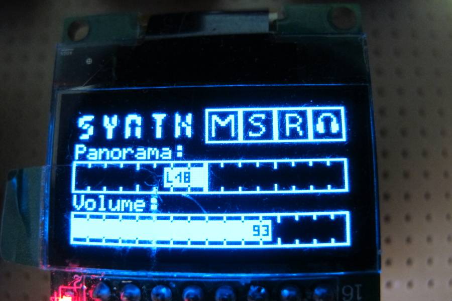
I really like John Finsters mackie setup here:http://www.midibox.org/dokuwiki/doku.php?id=john_e._finster#midibox_ng_mackie_control_clone_-_august_2013
and the custom fonts info here: http://www.midibox.org/dokuwiki/doku.php?id=john_e._finster#how_to_create_custom_glcd_fonts_icons_bars_for_midibox_ng
the section on the bars Panorama and Volume, i was hoping to pick johns brains a bit on this, but hes not been back in for a little while. I am reading his wiki page and the info and will have to try it out once i am more familiar with the code and its implementation in applying custom fonts. I also like the use of the mute/solo/record and monitor icons he used.
-
Yes, took a while but I am making sure that I am grounded in the basics. Looks like I need more practice. I am writing everything down as I go in my notebook. I finally got myself a breadboard today, first one I have ever owned!!! Go figure.
-
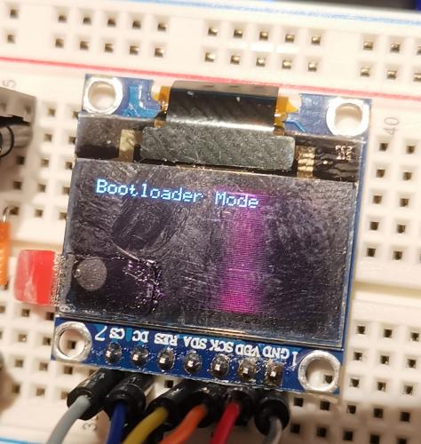
So.... after some food and a break I sorted it. The board was wiped and re programmed. It took then, wierd as It says on the one web page to get into bootloader press the blue button and hold then short press the black on the discovery board, however it wouldn't take that way. However tonight I get to try out some of the code I wrote on the display, really pleased.

-
Hey Bruno, its ok I have been having a total brain fart again and not checking my notes. I needed to start it up in mios32 bootloader.
I have it up now in mios studio as MIOS32 Bootloader in and out.
I forgot to hold the blue button down and tap the black to restart in bootloader mode on the discovery board.
all sorted now, thanks
-
 1
1
-
-
having an issue with the bootloader update this morning, it wont accept the set lcd type command --> set lcd_type GLCD_SSD1306
my mb_ng info
Operating System: MIOS32
Board: MBHP_CORE_STM32F4
Core Family: STM32F4xx
Chip ID: 0x10076413
Serial: #57003D001050484E52353320
Flash Memory Size: 1048576 bytes
RAM Size: 196608 bytes
MIDIbox NG V1.036
(C) 2018 T.Klosethis is what i get back: [ 476.439] set lcd_type clcd [ 477.522] Unknown set parameter: 'lcd_type'!
if i try the clcd line it also fails, was ok the other day.
if i type "help" in the linie this is the command list, there is no option of set lcd_type
[1902.530] Welcome to MIDIbox NG V1.036!
[1902.531] Following commands are available:
[1902.531] system: print system info
[1902.531] memory: print memory allocation info
[1902.532] sdcard: print SD Card info
[1902.532] sdcard_format: formats the SD Card (you will be asked for confirmation)
[1902.532] network: print network info
[1902.532] set dhcp <on|off>: enables/disables DHCP
[1902.532] set ip <address>: changes IP address
[1902.532] set netmask <mask>: changes netmask
[1902.532] set gateway <address>: changes gateway address
[1902.532] set osc_remote <con> <address>: changes OSC Remote Address
[1902.532] set osc_remote_port <con> <port>: changes OSC Remote Port (1024..65535)
[1902.532] set osc_local_port <con> <port>: changes OSC Local Port (1024..65535)
[1902.532] set osc_mode <con> <mode>: changes OSC Transfer Mode (0..4)
[1902.533] set udpmon <0..4>: enables UDP monitor (verbose level: 0)
[1902.533] keyboard <1|2> (or kb <1|2>): print current configuration of given keyboard number
[1902.533] set kb <1|2> debug <on|off>: enables/disables debug mode (not stored in EEPROM)
[1902.533] set kb <1|2> note_offset <0-127>: selects the note offset (transpose)
[1902.534] set kb <1|2> rows <0-16>: how many rows should be scanned? (0=off)
[1902.534] set kb <1|2> velocity <on|off>: keyboard supports break and make contacts
[1902.534] set kb <1|2> release_velocity <on|off>: keyboard supports NoteOff velocity
[1902.534] set kb <1|2> optimized <on|off>: make contacts only scanned if break contacts activated
[1902.534] set kb <1|2> dout_sr1 <0-32>: selects first DOUT shift register (0=off)
[1902.534] set kb <1|2> dout_sr2 <0-32>: selects second DOUT shift register (0=off)
[1902.534] set kb <1|2> din_sr1 <0-32>: selects first DIN shift register (0=off)
[1902.534] set kb <1|2> din_sr2 <0-32>: selects second DIN shift register (0=off)
[1902.534] set kb <1|2> din_key_offset <0-127>: selects the key offset between DIN1 and DIN2
[1902.535] set kb <1|2> din_inverted <on|off>: DINs inverted?
[1902.535] set kb <1|2> break_inverted <on|off>: Only break contacts inverted?
[1902.535] set kb <1|2> make_debounced <on|off>: Make contacts will be debounced
[1902.536] set kb <1|2> break_is_make <on|off>: Break contact will act like Make and trigger a note
[1902.536] set kb <1|2> delay_fastest <0-65535>: fastest delay for velocity calculation
[1902.536] set kb <1|2> delay_fastest_black_keys <0-65535>: optional fastest delay for black keys
[1902.536] set kb <1|2> delay_fastest_release <0-65535>: opt. fastest release delay for velocity calculation
[1902.536] set kb <1|2> delay_fastest_release_black_keys <0-65535>: opt.fastest release delay for black keys
[1902.537] set kb <1|2> delay_slowest <0-65535>: slowest delay for velocity calculation
[1902.537] set kb <1|2> delay_slowest_release <0-65535>: slowest release delay for velocity calculation
[1902.537] set kb <1|2> key_calibration <on|off> enables/disables key calibration
[1902.537] set kb <1|2> key_calibration clean clears calibration data
[1902.537] set kb <1|2> key_calibration_value <key> <delay> directly sets delay value
[1902.537] set midimon <on|off>: enables/disables the MIDI monitor
[1902.537] set midimon_filter <on|off>: enables/disables MIDI monitor filters
[1902.537] set midimon_tempo <on|off>: enables/disables the tempo display
[1902.537] router: print MIDI router info
[1902.537] set router <node> <in-port> <off|channel|all> <out-port> <off|channel|all>: change router setting
[1902.537] set mclk_in <in-port> <on|off>: change MIDI IN Clock setting
[1902.537] set mclk_out <out-port> <on|off>: change MIDI OUT Clock setting
[1902.537] testaoutpin: type this command to get further informations about this testmode.
[1902.538] caliaout: type this command to get further informations about this testmode.
[1902.538] testlcdpin: type this command to get further informations about this testmode.
[1902.538] set dout <pin> <0|1>: directly sets DOUT (all or 0..255) to given level (1 or 0)
[1902.539] show douts: prints the current DOUT patterns
[1902.539] set debug <on|off>: enables debug messages (current: on)
[1902.539] set autoload <on|off>: enables autoload after filebrowser upload (current: on)
[1902.539] save <name>: stores current config on SD Card
[1902.539] load <name>: restores config from SD Card
[1902.539] show file: shows the current configuration file
[1902.539] show pool: shows the items of the event pool
[1902.539] show poolbin: shows the event pool in binary format
[1902.540] show id <element>:<id> shows informations about the given element id (e.g. BUTTON:1)
[1902.540] show hw_id <element>:<hw_id> shows informations about the given element hw_id (e.g. BUTTON:1)
[1902.540] show ngr_tokens: shows .NGR token information
[1902.540] lcd <string>: directly prints a string on LCD (can be formatted!)
[1902.540] run [<section>] [<value>]: executes the .NGR script with the optional section and value
[1902.540] ngr_value: value used for 'run' (without parameter) and 'ngr' (is: 0)
[1902.540] ngr_section: section used for 'run' (without parameter) and 'ngr' (is: 0)
[1902.540] ngr <command>: directly executes a NGR command
[1902.540] ngc <command>: directly executes a NGC command
[1902.540] msd <on|off>: enables Mass Storage Device driver
[1902.541] reset: resets the MIDIbox (!)
[1902.541] help: this page
[1902.542] exit: (telnet only) exits the terminal -
lol again.. it was late and I was tired.. thats my excuse and i am sticking to it!! now its correct
-
got you, as such. will do later tomorrow, need zzz now, thanks again andy.
-
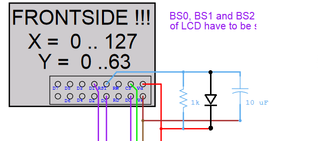
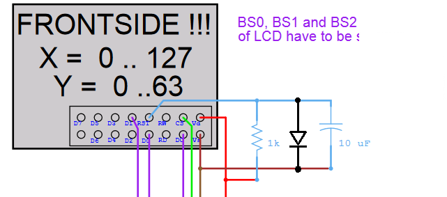
i noticed on the link here: http://www.ucapps.de/mbhp/mbhp_lcd_ssd1306_single_mios32.pdf
that there is a 1k resistor going from the 3.3v feed to reset and also a 10uF cap going from gnd to reset.
will i need to apply this to my oleds as well? mine are 7 pin: 1 gnd, 2 vdd, 3 sck, 4 sda, 5 res, 6 dc, 7 cs
-
well I have been playing around with the various commands and i seem to be getting to grips with this really quickly. I am going to attach one of my oleds tomorrow and try some of the code i wrote, have tried some tonight and its all worked fine.
hooked up a din etc and all is good there, moved syntax around etc and that was all good, this .ngc code is quite logical in how it works.
I did try the copy pase command sequence in mios, didnt like it!! so its one at a time.
thanks all have a great xmas, catch you onthe flip side.
-
pleased to report that all is working, one question, rather than input one line at a time eg: set lcd_type clcd then set lcd_num x 1 etc can you just input it all in one go? via copy paste into the mios text input bar?
thanks
-
oh boy... helps if i stuff the two IC's in the sockets as well..... oh dear..
LOL!!!!! welcome to dumbass 101
Thanks andy, have a great xmas, I am off to play with some code now!!
catch you all in the new year
-
ok i have that sent now
[11445.498] set lcd_type clcd
[11446.590] LCD type set to 0x00 (CLCD) after 'store'!
[11462.502] set lcd_num_x 1
[11463.594] LCD num_x set to 1 after 'store'!
[11472.272] set lcd_num_y 1
[11473.364] LCD num_y set to 1 after 'store'!
[11480.739] set lcd_width 40
[11481.830] LCD width set to 40 after 'store'!
[11490.256] set lcd_height 2
[11491.348] LCD height set to 2 after 'store'!
[11492.037] store
[11493.571] Failed to store new settings - retry #1
[11493.571] New settings stored.
[11493.571] Initialize LCD #1 -
i had the bootloader in etc already so for the fact im seem to have total loss of brain power where do i enter the lcd type etc?
mios gives me this
Operating System: MIOS32
Board: MBHP_CORE_STM32F4
Core Family: STM32F4xx
Chip ID: 0x10076413
Serial: #57003D001050484E52353320
Flash Memory Size: 1048576 bytes
RAM Size: 196608 bytes
Bootloader 1.018
(C) 2014 T.Kloseso its good
how where to enter the lcd info?
Thanks, and merry xmas to you too!!
-
right my Board: MBHP_CORE_STM32F4 is working and mios sees it. I have hooked an lcd up to it but im getting no response on the lcd, its lit up and i have trimmed the pots for contrast and backlight.
The connection is one to one as per the info I have just checked the data sheet on the lcd (2x40) and it is fine, the ribbon cable is also tested and fine.
I just checked the new lcd on a core and thats fine, but all i am getting are lit squares, so I am assuming it is because i have not defined the LCD as below
the information says that i need to tell it what lcd it is in the bootloader as per this section.
These parameters can be customized from the MIOS Terminal (part of MIOS Studio) by uploading the mios32_bootloader update application
What bootloader update application????
i find this example:
Example2: two HD44780 based 2x40 character LCDs are connected to your MIDIbox
Enter:lcd_type CLCD lcd_num_x 2 lcd_num_y 1 lcd_width 40 lcd_height 2 storeSo as I am using a single 2x40 i would apply this:
Example2: two HD44780 based 2x40 character LCDs are connected to your MIDIbox
Enter:lcd_type CLCD lcd_num_x 1 lcd_num_y 1 lcd_width 40 lcd_height 2 storeWhere and how would I apply this??
the information is really sketchy and I plan on updating things as i go, right now I am MB_NG newbie 101
Thanks
-
On 14/12/2019 at 7:01 PM, TK. said:
It would be too much effort to provide a 1:1 compliant solution.
Would it be sufficient if I provide new markers to address the display, and to set the Y position? (something like ^lcd and ^cursor_y)?
Best Regards, Thorsten.
lets put this in anyway as it will be good to learn how to implement this and I would like to see this function in the code. The only way to learn is to do and I really want to get into the ngc code over the winter here.
As I get to grips I will share on this thread.
Thanks Thorsten
-
One alternative, Will the mackie control, logic control be ported to use on the stm32f4? My daw supports this so I could go that way instead if needed.
-
I am just looking at whatever is the most time efficient solution for you if the software needs changing.
the ability to have this sysex: F0 00 01 06 16 12 00 00 00 73 74 72 69 6E 67 73 F7 this hex is an example ascii for the track name "strings": 73 74 72 69 6E 67 73 show on the oled is all i am looking for.
in an old thread someone asked you about sysex being used for a track name :
If there is a solution to the track name then I can work out how to do the level, pan etc in my own time as it is a starting point for me.
Many thanks
-
On 26/11/2019 at 8:24 PM, ssp said:
Hi THorsten, this is the reference to the hex to oled.
F0 00 01 06 16 12 00 00 00 73 74 72 69 6E 67 73 F7
this hex is an example ascii for the track name "strings": 73 74 72 69 6E 67 73
Also with regards to the small SSD1306 displays, the software i use uses sysex to talk to them,
here is the sysex from the midi implementation section of the manual
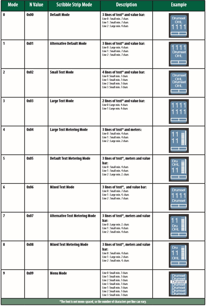
Value Bar Received:
B0, 3i, vv i Value bar number (0 thru 7) vv value (0 to 7F)
B0, 3i, mm i Value bar number offset by 8 (8 thru 15) mm Value bar mode (0: normal, 1: bipolar, 2: fill, 3: spread, 4: off)
B0, 4i, vv i Value bar number (0 thru 7) for strip 9-16 vv value (0 to 7F)
B0, 4i, mm i Value bar number (8 thru 15) for strip 9-16 mm Value bare mode (0: normal, 1: bipolar, 2: fill, 3: spread, 4: off)
Scribble Strips
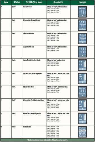
Addressing: Scribble Strip ID and Scribble Strip Line via SysEx:
Received:
Set Mode:
<SysExHdr> 13, xx, mn F7
xx = scribble strip id 0-7
m = bits 6 to 4
• bit 4 = 0 - do not clear the strings/ redraw old strings in new mode
[<SysExHdr> 0x13, 0x01, 0x05 F7] - Changes display mode to Mode 5 and redraw old strings in new mode
• bit 4 = 1 - clear strings / new strings will be send and drawn in new mode [<SysExHdr> 0x13, 0x01,0x12 F7] - Changes display mode to Mode 2 and clears the old strings for Scribble Strip #1)
• bit 5 = unused • bit 6 = unused n = mode number (bits 3 to 0)
Send String:
Send the text messages to the scribble strips. Received: <SysExHdr> 12, xx, yy, zz, tx,tx,tx,... F7
xx = scribble strip id 0-7
yy = line number 0-3
zz = alignment flag and normal/inverted
• flag bits xxxxiaa (0000000 = centered normal)
• aa = alignment (center: 0, left: 1, right: 2)
• i = inverted
• x = not used
tx = text in ASCII format
Metering
Channel Pressure message (After Touch) for the peak and reduction meters.
Received:
Dn, vv
n meter address
• 0-7 peak meters 1-8
• 9-15 reduction meters 1-8
vv meter value (0...7F)
Peak meters decay automatically.
Reduction meters are set by the host only (no automatic decay).
Program Change message for the peak and reduction meters 9-16.
Cn, vv
n meter address
• 0-7 peak meters strip 9-16
• 9-15 reduction meters strip 9-16 vv meter value (0...7F)
Peak meters decay automatically. 100% decay in 1.8 seconds.
Reduction meters are set by the host only (no automatic decay).
Running Status The following message is should be sent every second: A0,00,0
-
Thorsten I was wondering if the issue of receiving sysex channel names forwarded to the oled had been resolved? I did ask this in relation to a thread where it had been asked a few years ago. The channel name is sent from my daw via sysex and the text is ascii converted to hex as explained in this thread. Can you update me on this or if it is possible? Thanks
-
All is good with the faders, i need to open them up, clean and put some fresh teflon grease in there for the slider as it has dried up in them The calibration upper, middle and lower is goood, but will be better once serviced.
-
yea i got it Zam, i had to go get new batteries for me meter, if anyone had the data sheet it would have saved time. just put the meter over it and all sorted now thanks
-
does anyone have the data sheet for the old PANASONIC EVANMKP08B14 faders, looking for the pin info there doesnt seem to be any datasheet on the net. I want to use the old ones on another project so they dont goto waste. Touch isnt important as i have the alps for that.
thanks
-
Finished building the first mb_mf NG and hooked up a fader, all worked first time. Calibration is great through mios studio. Would have been great if it had the ability to have a lcd attached. Just waiting for the other pcbs to arrive now so I can get on with the ngc code learnings and trial!!


multiple Clcd's
in MIDIbox NG
Posted
I read in the lcd hardware section about putting multiple clcds onto the Ng is possible in this link : http://www.ucapps.de/mbhp/mbhp_lcd_6x2x20_mios32.pdf
Question:
Is it possible to attach 16 X 1 line 3 digit clcd's to the NG and have each one, via code linked to either a rotary pot or encoder in its value state? (would rather go this route)
i understand an easier option is to either use oled displays or a single 2x40 with padded values spaced equally however, thi cldcd route is something i really want to try out
I want to build a vintage plugin controller and it has 16 3 digit clcds in its on screen display.
The other reason for the clcds is that i want the old red segments.
the other option i thought of was using one 2x40 clcds and padding them out so there are 4 sets of values per line but each value is padded equally and shows the 0-127 value above each pot/encoder
now I understand the use of the padding for a name and the id-value, I just need a poke in the right direction as to which is the better option.