

ssp
-
Posts
659 -
Joined
-
Last visited
-
Days Won
4
Content Type
Profiles
Forums
Blogs
Gallery
Posts posted by ssp
-
-
4 minutes ago, totoRaymond said:
that's strange.
can you send your complete .ngc file?
and have you turned debug_mode on?
also what is the status of your router?
I had weird behavior related to these in the past.
the code is basic
this is the mios studio input: it replicates the fader movement
[8548.313] b0 10 03 Chn# 1 CC# 16 = 3
[8548.313] b0 10 03 Chn# 1 CC# 16 = 3
[8548.315] b0 10 02 Chn# 1 CC# 16 = 2
[8548.315] b0 10 02 Chn# 1 CC# 16 = 2
[8548.315] b0 10 02 Chn# 1 CC# 16 = 2
[8548.333] b0 10 00 Chn# 1 CC# 16 = 0
[8548.333] b0 10 00 Chn# 1 CC# 16 = 0
[8548.333] b0 10 00 Chn# 1 CC# 16 = 0 -
16 minutes ago, totoRaymond said:
I feel what you say.
Documentation on the midibox NG is sometimes wonky (some description are wrong case wise, I've lost nights chasing case sensitive statements) but the software is so good....
I'd like to be able to correct things on the documentation sometimes.... or just add comments so people after resolve same problems faster.
still, MidiBox is an awesome project. It deserves to be supported by a lot more people. I'd like to become part of the team though i don't feel worthy of it.
Cheers,
Thomas
yes the ngc format is so much easier to go through than the old assembly!! but i got to grips with that in the end.
I am trying to get to grips with everything then apply it in the thread in a more simplistic way for those coming in new and also it helps me visualise things better.
I just got the fader working on the core once it was written it was simple
# AIN hardware
AIN enable_mask=10000000 ( I am assuming that the 8 digits refer to the 8 pins on J5a/b and for an active pin you put a 1 in place?
# EVENTs
EVENT_AIN id= 1 type=CC chn= 1 cc= 16 range= 0:127It works but i get double figures in mios studio when i move the fader
such as
Chn# 1 CC# 16 = 22
Chn# 1 CC# 16 = 22
Chn# 1 CC# 16 = 23
Chn# 1 CC# 16 = 23Is this a bit resolution that i need to add into the ngc code to prevent the doubling up on the fader movement into mios studio?
Thanks
I need some zzz now so will test the code tomorrow
-
13 minutes ago, totoRaymond said:
Hi ssp,
I never used it but yes, it seems that if you connect a fader or pot to J5A, you need to use AIN statement first to describe the physical thing.
then use EVENT_AIN to describe the behavior of said event.
If you'll use bank on that parameter, you need to use different "id" for each bank but they should all refer to the same "hw_id"
I hope it's clear enough, sometimes i find it difficult to explain such things in human language. (plus english is not my mother tongue)
Cheers,
Thomas
Yes i understand the "bank" setup and hw id's, it was just finding an example of setting up the fader on j5a as the only other time i have used it is with an ainser64 and i dont need one of those right now. sat going through the ngc info again to see whats what, there is so much missing info wise that was never added along with the solution to having multiple ssd1306 but it still refers to j28 on the lpc pcb and nothing for the stfm pcbs. it would be good to get some of these updated as others have had to edit mios rather than configuring the ngc which is easier for users.
-
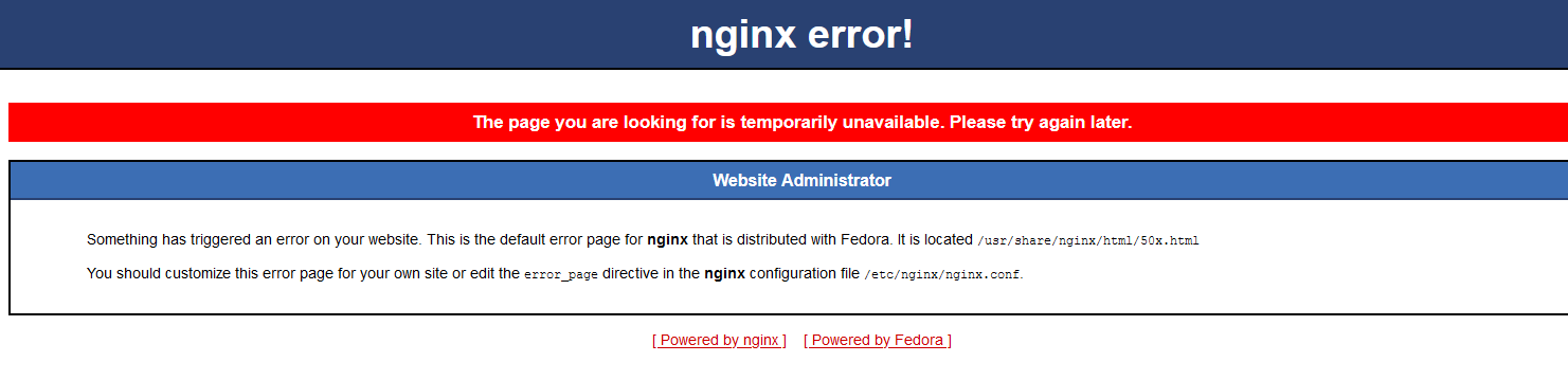
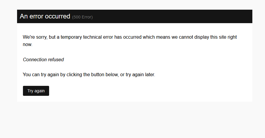
We need the site admins to check in with the hosts to see whats going on as the forum is having daily errors now.
tonight along with the internal server error 500 that most get I am now getting the nginx error page and this is constantly every couple of mins.
-
Question:
I want to test the bank code i have written, I am going to assign in to a fader connected to j5a on the stfm core.
Would i use the EVENT_AIN function for this?
I just want to connect a fader directly to j5a, so how would i implement this rather than using an ainser8 or ainser64?
thanks
-
nowhere else for me to post but i keep getting site issues, anyone else getting this??

-
38 minutes ago, totoRaymond said:
Hi,
About your LCDs, i was going to advise to check your voltages, too much of a voltage drop on a long run can give weird behaviours, especially on proto boards.
But anyway, you figured that out.
About your second question, there are multiple ways of achieving this. What is it you really want? One single button to cycle through a number of banks?
You can use meta= CycleBank for that. i didn't use it myself, so you might want to make some tests.
But basically, you have multiple events, with unique ids, but same hw_id, and unique bank#.
you button should be set to event= Meta meta= CycleBank mode= OnOnly i guess
This should get you started. but be aware that this will cycle the bank for ALL parameters with bank ids available.
Thomas
yes this is what is in the git hub, i am thinking of two buttons, -bank and +bank, i am still reading things and writing bits down to work on this week
Thanks for the info Thomas @totoRaymond
-
I am looking at the banks and other functions today.
I am sure I have seen this discussed somewhere ( having a forum search to find it)
can you have multiple control parameters on a fader, potentiometer or encoder from a button press
So if you want one fader to control ADSR features.
on its 1st function its cc16 assigned to the amplitude
press a button and then
its second function is cc17 assigned to decay
press again
third function is cc18 assigned to sustain..
and so on
Would this be a combination of mapping and radio buttons? I am playing around with the code today seeing if i can make a happy accident.
I am currently reading the enc_banks on teh git hub
https://github.com/midibox/mios32/blob/master/apps/controllers/midibox_ng_v1/cfg/tests/encbanks.ngc
Tx
-
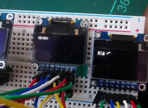
Question, i have 8 oleds hooked upto the st core, the first 7 work fine but the 8th keeps corrupting, it will not display the text correctly.
the lcd number in the mios setting is for 8 only, i just erased the st board and re uploaded mios and the mb ng software, all is good but 8 is still garbled, i used other oleds i have here incase it was faulty, moved it around and i also got my two spare st boards and programmed them also. Still the same barled text on number 8 only, any ideas?
The pcb is clean and soldered correctly no bridges or any issues.
Update: Problem solved, needed more voltage so moved the j15_S from 3v3 to 5v
-
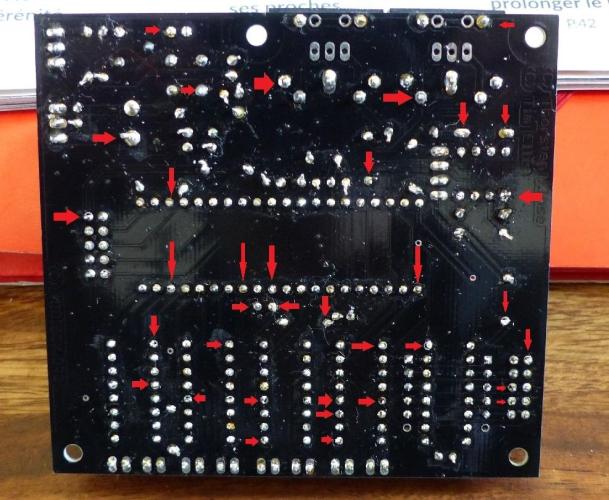
sorry it took so long to answer this for you.
I am looking at the soldering on the rear and I can see that some of the pic socket pins are not soldered correctly to the pads and some not at all it seems. reflow the lot on the back, just place your soldering iron on the pad and push some solder in gently to flow better.
Get some isopropyl alcohol from RS or Farnell etc to give the board a clean then.
-
Thanks for the reply, thats a little beyond my scope messing with mios, I am good with the ng code structure. It is a shame that the MB_NG user manual section on hooking up the ssd displays was not updated in relation to the discovery boards.
The reference of using J28 being the older lpc17 MB and not relating to the discovery pcbs most are now using.
Perhaps it's something @TK. could give us some info about when he has time to do so, I understand he is in here very little these days but hopefully, this is one of the outstanding issues that can be resolved.
Thanks again for your help both most appreciated
-
Thanks for the heads up @latigid on, hopefully @Phatlinecan give me some more info, I can add it to my thread along with some pics. I am just using the ssd1306 oleds. But at some point a controller with several clcd's will be on the cards
-
just saw this, I am working on a controller and would like to bump it upto 16 displays, when i go into bootlader and enter the number of displays as " set lcd_num_x 16 " does this mean that i can pick up the extra Cs lines from J10B without changing anything else and still use the standard control surface on J10A
Just hook the displays up as i have on the first 8? each display having its own cs line.
Thanks
-
As soon as I have some free time I will edit it and run it again.
-
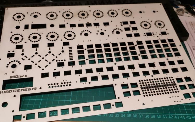
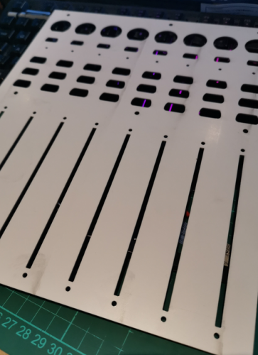
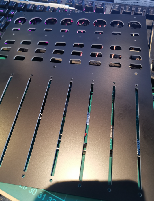
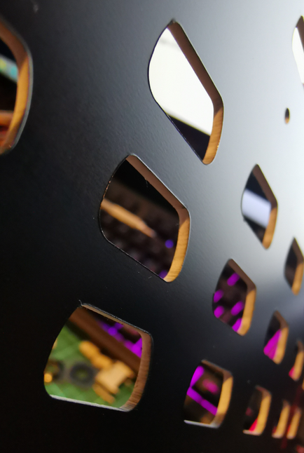
The text is no good, it's plain lines and not a scan engrave text soi need to edit it. The lines are single lines and also not etch able these need editing also. The numbers are the same. Other than that it is OK. Just needs cleaning.
-
 1
1
-
-
Hi Smithy
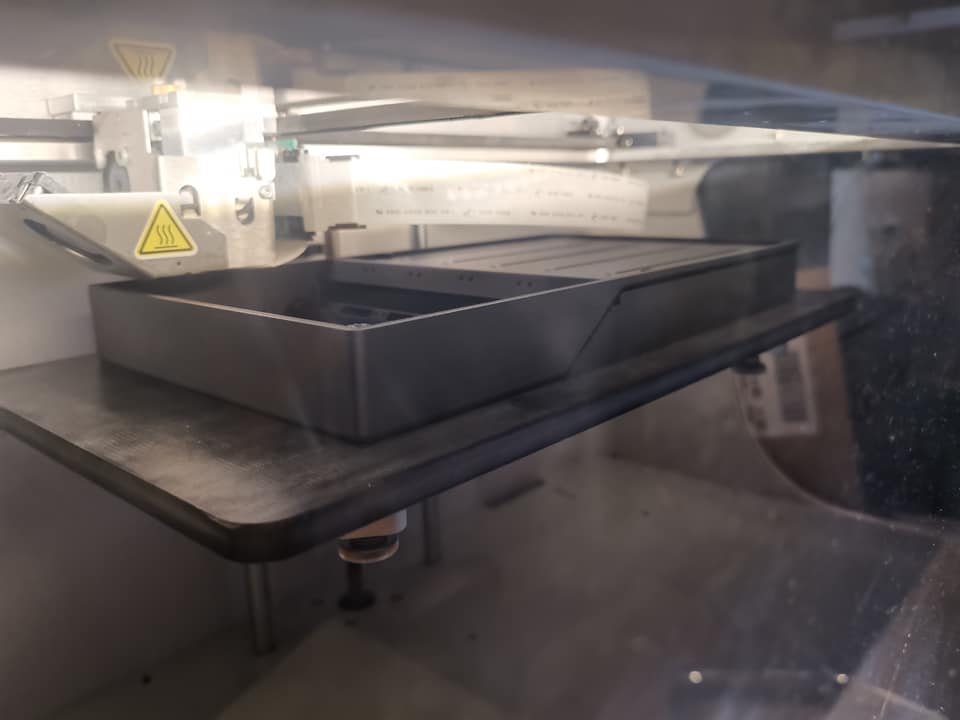
Yes there is dual colour laser material, we use it. we dont use a real thick one, its about 1.5mm thick.
The atacam removes the text or graphics from the top layer of black using a scan feature, then does all the cuts through.
I am in the middle of hacking two old mackie control units, to make a custom controller. This is for doing a test fit for the boards.
I am in next week so i will do a small section of the panel for you to see how it comes out.


-
I messed with kicad a long time ago, i got into eagle more and really got to grips with that, exporting the gerbers over into flatcam for milling pcbs on a small cnc machine.
These days i use Altium everyday and also Solidworks pcb which has a cut down version of Altium in. Altium has the Solidworks Connector extension installed and i run a local SVn server that allows me to push the altium pcb through into solidworks directly, that way i can edit the enclosures around the pcb and push back and fore, If i move a part on the pcb in Solidworks and push back to Altium it shows me the change and allows me to re-edit the traces/Layers etc and then push back.
I never upgraded my Eagle, i still have the old V7 cadsoft version, dont like the new version at all.
-
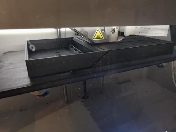
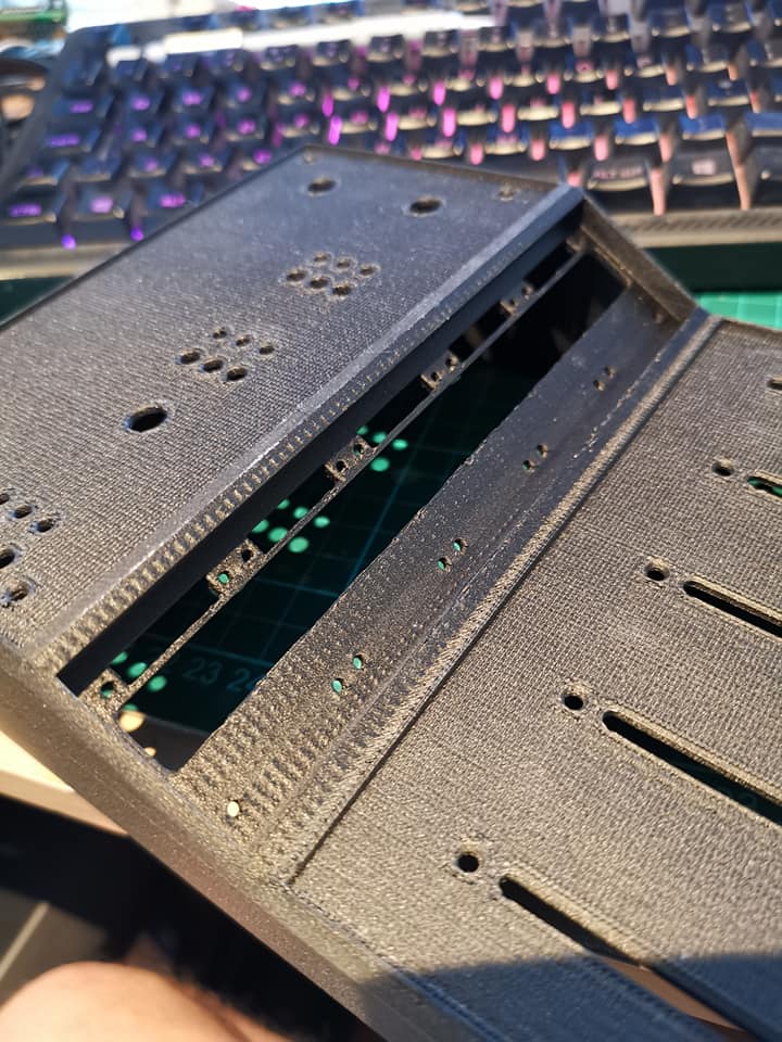
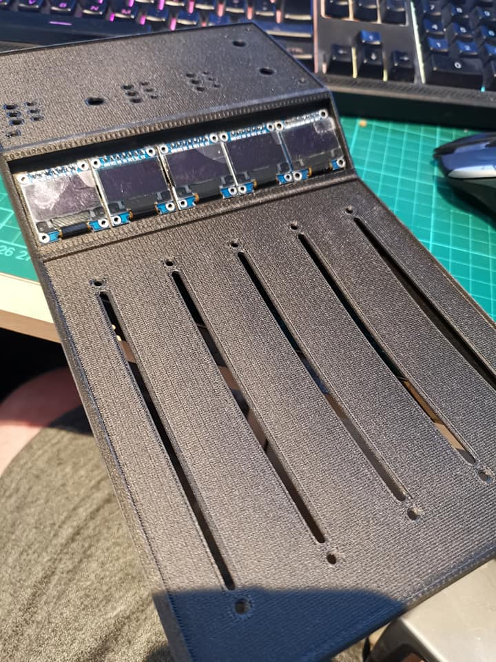
been busy working on various projects, finally got time to print the enclosure for one of them this weekend. Designed in solidworks and printed in Carbon/Nylon.
I have 5 alps motorised faders to fit and a few buttons, leds and pots to go on a pcb i am milling next week.
There are insert faceplates to do yet on the fader face and the upper face.
All is looking good though so far and the cade is working as well, I am also making a small dout x2 pcb as well as i only need 9 leds, i am using a TSSOP16 74hc595 and a smt resistor network to reduce the size for the space i need in the enclosure.
Using jlcpcb in china for a couple of different boards as they are far too expensive to be made in the uk.


-
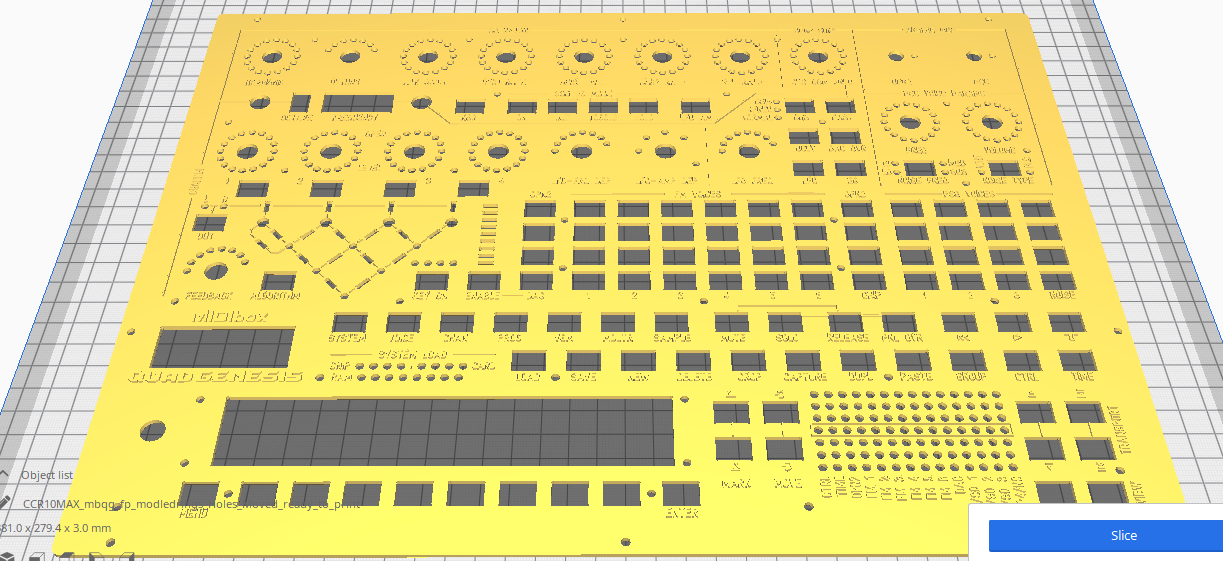
On 1/31/2021 at 4:05 PM, Smithy said:
[3D Printable Front Panel File for use by Wiki]
mbqg_fp_modledrings_Holes_Moved_ready_to_print.zip
Attached is an STL file of the front panel with raised lettering for use with 3D Printing
To produce a bi-coloured panel with a different colour for the lettering please follow this easy guide:This file is provided as a lower cost method for producing a 3D printed front panel as opposed the cost of having an alluminium panel milled by Schaeffer which costs 410 euro in the EU excluding shipping.
However, it may be better to use an SVG file to have acrylic laser cut, which will be cheaper to order online and have more accurate cuts and engravings.
I have an SVG file ready and working with the Formular.de ordering system, but it is not currently compatible with Ponokos ordering system so I have emailed them.I will update the thread if I make any progress with Ponoko.
Here's a preview of the 3D Printable STL file:
Hey Smithy, i have an Atacam laser system in work i use, do you have this as a dxf file? i can do a panel test when i call in next week. I can do a cut on some 2, 3 or 4mm laser acrylic and see how it comes out. I can set the text to scan engrave and the rest to cut, probably take a couple of mins.
-
Is it possible to change the font size when using the ssd1306 oled's? Is this set in mios studio while the stf32m is in bootloader mode.
when entering the , set lcd_type etc?
UPDATE: I found the section i needed in the NG usermanual.
GLCDs can output different fonts which are selected with the ampersant (&) character:
- &&: outputs the & character
-
&<font>: selects a font for graphical LCDs:
- &n: selects the "normal" 6x8 font
- &i: selects the inverted 6x8 font
- &s: selects the "small" 4x8 font
- &t: selects the "tiny" 4x8 font
- &b: selects the "big" 24x16 font
- &k: selects "knob icons", a 24x32 font. Values can be output with %B
- &h: selects a meter with horizontal orientation, a 32x8 font. Values can be output with %B
- &v: selects a meter with vertical orientation, a 8x32 font. Values can be output with %B
And finally it's also possible to change the output LCD and position within a label:
- @(<lcd>:<X>:<Y>): changes to the given lcd, X and Y position.
Example:
lcd_pos=1:1:1 label="Enc%3i&k@(1:1:2)%B&n@(1:18:1)%3d"
No, this is not an encrypted message, because the processing rules are well documented! ;-) - it will output "ENC" + the ID number. Then it will select the "knob" icon, jump to position X=1 Y=2 and output the knob icon based on the EVENT value. Thereafter it will select the normal font, jump to position X=18 Y=1 and output the MIDI value in decimal format.
all is good
-
For me here in the UK the pricing and MOQ meant that i had to get a lot of things either from ebay or ali express as the pricing in the UK was far too much. For example i wanted some 6mmx6mm square led tact switches, in the UK they were almost $5 each equivalent. I got them from Ali express for $10 for 20 of them. same with the mini 7 segments, encoders and components. In the UK its V.A.T on everything, then customs etc and forwaring postage costs with VAT added.
I just got a quote in for one of my pcbs, its a 4 layer pcb 250mmx250mm it was £90 for the pcb and then a further £140 for the processing, jlcpcb in china quoted me under £100 for 5 of the pcbs with shipping etc. I rarely get anything from the UK side anymore.
-
perhaps you need to look at the blm then?
-
29 minutes ago, latigid on said:
Just post here! I think you would make great friends with Mr. @ssp :)
hmm.. i probably ask more questions that I already know the answer to.. it just takes me a little while to catch up with my brain.
So i am looking at the question, so am i correct in you want to build a controller to control a drum machine plugin in logic? Please bear in mind I dont use logic i use presonus studio one, i havent turned my mac on in years and its an old G4 mirror door!!
You could have a look through my thread in the MBNG section, it shows me learning the basics and progressing slowly, making mistakes and asking for help.
I dont always understand it straight away but I get there eventually as it shows as I progress.
If I can help I will, otherwise the other members will step in I am sure ;) @latigid on ;)
One thing try using a good powered usb hub and plug your mbng into that, thats how i am running mine.
-
i had another go at trying to get the encoder to switch between each function as the buttons would however when the encoder changed to another function it didnt enable that as if i had pressed the button "on"
i can go back and fore the 3 displays and then press each button to activate the corresponding value to change with the other encoder
would i use a "soft" button or an event sender so that when i turn the selection encoder from its first point "lfo mod" to its second point "lfo res" and when it is on the second automatically put it in a "button on" state so i can then use the second encoder to change the value?
I am going to have a play around, I can't find anything like this talked about on the forum so I thought I would ask.
Thanks for any help. hopefully i can figure it out!
Could i use a meta event to send the button on? ie: meta=SendEvent:button_mode ononly


understanding the .ngc code
in MIDIbox NG
Posted
so using this just to tect the fader
RESET_HW
# AIN hardware
AIN enable_mask=1000
# EVENTs
EVENT_AIN id=1 type=CC chn=1 cc=16 range=0:127
i get this in the input window of miosstudio it jitters around while using the fader
[9150.059] b0 10 56 Chn# 1 CC# 16 = 86
[9150.062] b0 10 57 Chn# 1 CC# 16 = 87
[9150.069] b0 10 5a Chn# 1 CC# 16 = 90
[9150.071] b0 10 5b Chn# 1 CC# 16 = 91
[9150.076] b0 10 58 Chn# 1 CC# 16 = 88
[9150.077] b0 10 5e Chn# 1 CC# 16 = 94
[9150.078] b0 10 5c Chn# 1 CC# 16 = 92
[9150.080] b0 10 5e Chn# 1 CC# 16 = 94
[9150.081] b0 10 5c Chn# 1 CC# 16 = 92
[9150.082] b0 10 5e Chn# 1 CC# 16 = 94
[9150.083] b0 10 5d Chn# 1 CC# 16 = 93
[9150.084] b0 10 5f Chn# 1 CC# 16 = 95
[9150.085] b0 10 61 Chn# 1 CC# 16 = 97
[9150.086] b0 10 5e Chn# 1 CC# 16 = 94
[9150.089] b0 10 60 Chn# 1 CC# 16 = 96
[9150.092] b0 10 61 Chn# 1 CC# 16 = 97
[9150.093] b0 10 62 Chn# 1 CC# 16 = 98
[9150.097] b0 10 65 Chn# 1 CC# 16 = 101
[9150.098] b0 10 67 Chn# 1 CC# 16 = 103
[9150.099] b0 10 63 Chn# 1 CC# 16 = 99
[9150.103] b0 10 66 Chn# 1 CC# 16 = 102
[9150.104] b0 10 64 Chn# 1 CC# 16 = 100
[9150.106] b0 10 66 Chn# 1 CC# 16 = 102
[9150.110] b0 10 67 Chn# 1 CC# 16 = 103
[9150.113] b0 10 68 Chn# 1 CC# 16 = 104
[9150.117] b0 10 67 Chn# 1 CC# 16 = 103
[9150.118] b0 10 6b Chn# 1 CC# 16 = 107
[9150.119] b0 10 69 Chn# 1 CC# 16 = 105
[9150.122] b0 10 68 Chn# 1 CC# 16 = 104
[9150.123] b0 10 6a Chn# 1 CC# 16 = 106
[9150.124] b0 10 6c Chn# 1 CC# 16 = 108
[9150.126] b0 10 6b Chn# 1 CC# 16 = 107
[9150.129] b0 10 6d Chn# 1 CC# 16 = 109
[9150.130] b0 10 6c Chn# 1 CC# 16 = 108
[9150.137] b0 10 6e Chn# 1 CC# 16 = 110
[9150.138] b0 10 6d Chn# 1 CC# 16 = 109
[9150.142] b0 10 6e Chn# 1 CC# 16 = 110
[9150.146] b0 10 70 Chn# 1 CC# 16 = 112
[9150.148] b0 10 72 Chn# 1 CC# 16 = 114
[9150.149] b0 10 6f Chn# 1 CC# 16 = 111
[9150.153] b0 10 70 Chn# 1 CC# 16 = 112
[9150.158] b0 10 71 Chn# 1 CC# 16 = 113
[9150.162] b0 10 72 Chn# 1 CC# 16 = 114
[9150.163] b0 10 74 Chn# 1 CC# 16 = 116
[9150.166] b0 10 76 Chn# 1 CC# 16 = 118
[9150.167] b0 10 74 Chn# 1 CC# 16 = 116
[9150.168] b0 10 73 Chn# 1 CC# 16 = 115
[9150.169] b0 10 74 Chn# 1 CC# 16 = 116
[9150.173] b0 10 75 Chn# 1 CC# 16 = 117
[9150.178] b0 10 76 Chn# 1 CC# 16 = 118
[9150.184] b0 10 74 Chn# 1 CC# 16 = 116
[9150.185] b0 10 77 Chn# 1 CC# 16 = 119
[9150.191] b0 10 78 Chn# 1 CC# 16 = 120
[9150.193] b0 10 7a Chn# 1 CC# 16 = 122
[9150.203] b0 10 7b Chn# 1 CC# 16 = 123
[9150.207] b0 10 7c Chn# 1 CC# 16 = 124
[9150.214] b0 10 7d Chn# 1 CC# 16 = 125
[9150.217] b0 10 7e Chn# 1 CC# 16 = 126