

ssp
-
Posts
659 -
Joined
-
Last visited
-
Days Won
4
Content Type
Profiles
Forums
Blogs
Gallery
Posts posted by ssp
-
-
3 hours ago, FantomXR said:
Isn't that a usecase for MAPs? I haven't tried it but I'd set up an encoder in absolute mode and setup a MAP as range.
In the NGR you can tell NG to set the encoder to a dedicated value when starting up.
Is this what you are referring to (by example) and use this as a starting point? this is for a single button, i would need for this to be over two buttons.
https://github.com/midibox/mios32/blob/master/apps/controllers/midibox_ng_v1/cfg/tests/mapbtn.ngc
RESET_HW LCD "%CMap Button Values" # the used map: MAP1 0 1 2 4 8 16 32 64 # define a radio group with a single toggle button but multiple LEDs EVENT_BUTTON id= 1 fwd_to_lcd=1 type=CC chn=1 cc=16 button_mode=Toggle range=map1 radio_group=1 lcd_pos=1:1:1 label="^std_btn" # Note: the map will only be considered if a button is configured for button_mode=Toggle ! # these LEDs are mapped to radio_group1, and therefore will get an "automatic feedback" whenever the toggle button changes the value (or receives a new value) EVENT_LED id= 1 range=0:0 radio_group=1 EVENT_LED id= 2 range=1:1 radio_group=1 EVENT_LED id= 3 range=2:2 radio_group=1 EVENT_LED id= 4 range=4:4 radio_group=1 EVENT_LED id= 5 range=8:8 radio_group=1 EVENT_LED id= 6 range=16:16 radio_group=1 EVENT_LED id= 7 range=32:32 radio_group=1 EVENT_LED id= 8 range=64:64 radio_group=1 # a button which doesn't toggle, but just turns on/off # in this case either the lowest or highest item of a map will be taken EVENT_BUTTON id= 2 fwd_to_lcd=1 type=CC chn=1 cc=17 button_mode=OnOff range=map1 radio_group=1 lcd_pos=1:1:1 label="^std_btn"
-
2 hours ago, FantomXR said:
Isn't that a usecase for MAPs? I haven't tried it but I'd set up an encoder in absolute mode and setup a MAP as range.
In the NGR you can tell NG to set the encoder to a dedicated value when starting up.
Thanks for the info
I remember on the MB64e you could change the inc,dec buttons to an encoder with a slight code change. In effect this is the opposite, an encoder function to, two buttons, with a range of 0-100 instead of 0-127. and each button press has a stepped range of 20. however after pulling another late night the first press is 0-20 the second press actually starts at 20.5 as this is a marginal step over 20 it changes the plugin transpose position but you can round this to 21.
hopefully i will give it a try today, im not holing out for much success as i cant see any reference to a function for buttons like this on the forum or in the manuals other than the enc_mode or the emu_enc_mode functions.
I am writing test lines of coade as shown in the "First steps" section and trying things as i go.
I have got a few other things working but this and the 3 digit values issue are griefing me.
-
In this case would I use either the: enc_mode= Incxx_Decxx. Or would i use emu_enc_mode=<mode> Incxx_Decxx function and use the +or- 20 values in hex.
This seems logical to me. once this is in place i then have to have each value linked to each led. so if the value is 41-60 (this is the range of the value for the 0 position led to be lit and active and can be any number between that range)
so for example for the steps i want:
enc_mode= Inc14_Dec14 (this is the hex value for the decimal value of 20) im sure an event_reciever is needed also but I am not sure where to implement this.
I am looking through this page here: https://github.com/midibox/mios32/blob/master/apps/controllers/midibox_ng_v1/cfg/tests/emu_enc.ngc
to see if this can help me.
-
this is a good comparison in the manual where a dimmed LED steps in values of 16
 Dim me!
While previously the LED was only switched between on and off state depending on the incoming MIDI value, now we want to control the brightness level with the received velocity value instead:
EVENT_BUTTON id=1 fwd_id=LED:1 dimmed=1 type=NoteOn key=36 lcd_pos=1:1:1 label="Button #%3i: %3d"
Only the dimmed=1 parameter has been added. The LED will change the brightness over the 0..127 value range in 16 levels.
Just for fun you could also control the brightness from a CC event:
EVENT_LED id=1 dimmed=1 type=CC cc=16
-
OK question. I want to have to buttons function as an down value and one as an up value rather than using a pot or encoder.
I have two buttons linked to the din module and in effect they are replacing an encoder for the up and down values but in essence are acting as an encoder.
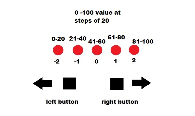
The buttons work like this, the maximum values needed for this are 0 to 100 not 0 to 127 but in steps of 20 these are for transposing the plugin i am using
values:
-2:= 0 - 20
-1:= 21 - 40
0=: 41 - 60
1=: 61 - 80
2=: 81 - 100
so if the button is in the middle ie:"0" then the button state is at a value between 41 - 60, if i then press the left button once the value changes to 21 - 40 and again to 0 - 20, if i then press the right button it brings the values back up.
OK so i have got a din with two buttons conencted to the mb_ng. on the first shift register to replicate an encoder such
ENC n= 1 sr=1 pins=0:1 type=non_detented (an encoder uses two of the sr pins)
each press of the button on sr=1 pin:0 is the left button with a decreasing value of to 0 in steps of 20
pressing button on sr=1 pin:1 increases the value by 20.
would i need to make a value table or meta event for this? to make each button press of either decrease or increase the value of the set range 0-100?
I am looking at the manual as I am typing this but I cant see anything that resembles this.
In other good news more of my bits turned up, also my ainser64 have arrived so I building those as well.
Thanks
EDIT: so the buttons will work as an encoder thats fine, i just need to set the min-max value range of 0-100 instead of 0-127 but it needs to travel in values of 20 at each press. Can i set this value range and steps?
-
13 hours ago, latigid on said:
Upload your NGC. Are you using SENDER/RECEIVER events? Did you scale/interpolate one CC into another? What about using the native CC scaling with -63/-/64 on the display? Did you look at maps?
nope none of the above, i didnt go with the -63/-/64 as i am trying to make a replica controller of the plugin. I can get the usual bit working encoders pots, linking the 7 segments to the dout and assigning it in the code etc. I have no idea about nrpns , how to work them out etc. I have however printed out some info sheets and I will see how i go. I have learned so much already, i just have to push a bit more, if i fail then at least I have tried. I am trying with just one pot and one 3 digit lcd. But if there is something in the manuals point me to it and I will read through it

-
I spent the weekend trying to get the nrpn to work but I failed.
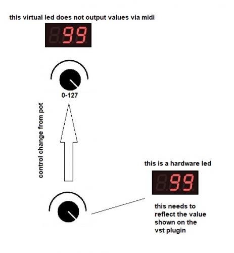
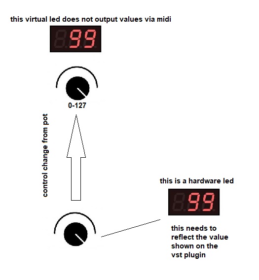
this is the issue that I couldn't resolve a dual command. The potentiometer needs to send a cc# to the vst plugin, it still expects 0-127 to move the virtual knob, the on screen 3 segment shows -99 to 99 values with a line for 0 as i have shown.
The 3 digit 7 segment I am fitting into my controller needs its instruction from the core not the plugin as the plugin does not output its led values out via midi. so the pot needs to send two different commands.
If i have to use nrpn this needs to only effect the hardware 3 digit display.
In simple turms, turning the potentiometer outputs both a cc# to the vst plugin and also changes the value on the 3 digit 7 segment display to reflect the on screen led value.
Everything else I have been working on has been fine and I have understood it, but this is seriously pickling my brain, its there but i just dont see it for some reason.
I could really do with some pointers on this. or..
basically can someone smarter than me help and point me in the right direction.
thanks
-
4 hours ago, TK. said:
Here the example:
- NGC: https://github.com/midibox/mios32/blob/master/apps/controllers/midibox_ng_v1/cfg/tests/runscr6.ngc
- NGR: https://github.com/midibox/mios32/blob/master/apps/controllers/midibox_ng_v1/cfg/tests/runscr6.ngr
Since in the NGR script the new "range" feature is used, you've to try it with the latest MBNG version
Best Regards, Thorsten.
Puts hand up... quite freely admits that I dont understand how to do this.
Sorry really not smart enough.
-
i use presonus studio one, the track names are spat out as asci converted to hex, its in my one thread. I have been meaning to test the code i have written but forgot about it as I was soucing parts and building.
I will give it a try tonight see if i can get it to work on mine.
S1 output per channel
F0 00 01 06 16 12 00 00 00 73 74 72 69 6E 67 73 F7
this hex is an example ascii for the track name "strings": 73 74 72 69 6E 67 73
this changes as you either tab over channels or bank swap as you would expect for more than 8 channels.
thread start from here: http://midibox.org/forums/topic/21235-understanding-the-ngc-code/?page=2
there was also this comment that had been previously made that i needed to find to link into the thread for throsten to look at
http://midibox.org/forums/topic/17498-midibox-ng-release-feedback/?do=findComment&comment=185392
-
Just now, TK. said:
In MBNG it's a soft-option written into the NGC file:
AINSER n=1 enabled=1 cs=0 num_pins=64 resolution=7bit
which allows to set the number of pins
Best Regards, Thorsten.
Thank you Thorsten, as soon as the pcbs arrive i will edit the code for this and try it out along with the new revision for NRPN numbers.
-
When I use a core 8 for a build and i want to do some testing, I usually just connect one fader or pot to J5 on the core and then I edit the code as shown
by default using the MB_64e V2 it is:
#define DEFAULT_NUMBER_AIN 64
#define DEFAULT_ENABLE_AIN_MUX 1
if you only have one fader you need to link any unused pins to ground however, I always just change the code to this and everything is fine as it is not expecting any other inputs.
#define DEFAULT_NUMBER_AIN 1
#define DEFAULT_ENABLE_AIN_MUX 0
This makes the core happy and only sees the one input.
My question is can I also edit the MB_NG in a similar manner for the Ainser 64 rather than having to ground all the other pins?
This is such a time saving way for me to check and test a single pot or fader.
I dont have my ainser 64 pcbs from the states yet so I have no way of trying it for myself rather than asking a question.
thanks
-
2 hours ago, latigid on said:
Just use MIOS Studio and assign one of the sliders to your CC event, or rather assign your event to one of the sliders.
You can probably use J10 or J5 as analogue inputs.
I didnt think of that, I want to try and figure out the nrpn this weekend (this is dependent on my ability to keep a stable path for the required neuro transmitters to create a link from the correct areas of my brain to form a cognetive thought and also hold a stable enough charge to allow the required areas to form a coherant memory) or in simple terms... not have a brain fart and have a mild ability to understand stuffz....
-
Question, is it possible to connect a single pot to the MB_NG without the ainser?
i have got a single 3 digit 7 segment here and and single pot on breadboard, so i can try working out the code for the nrpn -99/-/99 values. and see if it will work.
thanks
edit,, just the pot info is needed
-
20 hours ago, TK. said:
Important: when you are experimenting with NRPN, please use the latest version which got a fix for the NRPN numbers: http://www.ucapps.de/mios32/midibox_ng_v1_037_pre9.zip
(I will release this soon to make the changes official)
Best Regards, Thorsten.
Ah i just saw this been busy making solder fumes here!
thank you TK
-
grabbed some info on NRPN's also info on lsb and msb messages etc. So spent some time looking at those and the info on the matrix for the glcds. Lots to learn while I wait for my Ainser to arrive from the states.
Looking forward to trying things, failing, trying, failing and then working it out eventually! lol
Tried a few things out this evening with an older core8 , had to change some of the code and recompile (I manged to remember how to do that!!) and it all worked back and fore.
Going to work on the case work tomorrow and the overlay graphics before i get it printed onto overlay vinyl and laser cut.
More to follow ;)
-
i am building another controller with a core8 I have here. i am pretty sure that I can do this but I thought I would check first
I need to have a 5 position rotary switch and each switch has a preset cc# value from 0-127 to it,
For example we will use cc#16
Pos1: cc#16=20
pos2: cc#16=40
pos3: cc#16=60
pos4: cc#16=80
pos5: cc#16=100
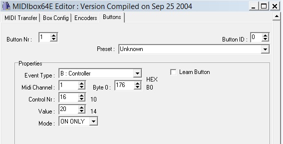
I am right i can do this as the rotary switch is attached to the Din input and i can just either edit the assembly or if I remember rightly you can use the mb64e editor to set this value.
Just digging the parts out to try it anyway, will post how it goes!!
Update: All sorted I remembered correctly, I can set it in the editor and save it there. That is the last thing i needed to check for this build. Happy solder geek ;)
-
Thanks Andy.
I have all the design and casework etc all figured out, how to cennect everything i have drawn out, I have to get an Ainser64 as I thought we could use the old Ain boards with the MB_NG but I see that the new Ainser is what is required so I will order a couple from modular addict tonight.
I may also speak with Smash and Thorsten if i can and see about getting a batch of MB boards made for UK stock from the PCB Fabricator I use that supplies the company I work for, they are based in south wales and give me great prices on runs wether for a single or batch orders.
I am reading through the Matrix section tonight, I browsed nrpn a long time ago, so I need to brush up on that
I am going to get the unit design finished and built as I am going, documenting it as I go. Perhaps start a blog here too.
Thanks again I do appreciate the input, it just gets frustrating when things refuse to click and i simply dont understand it.
I think the first thing to do is hook up one potentiometer and one 3 digit 7 segment lcd and being with that, once I understand how to make the code function for that , then I can apply it for the number I need.
Just gotta wait for the ainser's now!!
-
I have a pickit 3 and its been great, not had an issue with it for my older cores, the 452 works perfectly in it. i havent used anything else, i only just picked back up with the midibox kits, family life and work gets in the way. But programming the 452 in the pikit was simple and even I followed the instructions correctly and thats saying something!! lol
-
Thanks for the info.
you know a lot of this is new to me and i am slowly getting to grips with it, most of it though i am struggling with but i am trying to understand it.
I gotta be honest, I have always struggled with code, everything else I am ok with, I am not lazy and I am reading and trying as i go along I know how this place works been here long enough ;)
this is all new to me and I will ask questions as I go, they may seem stupid to most but if I dont ask then I wont learn.
I didnt see the dout matrix as i hadnt got to that part in the manuals.
The way i work is i learn in sections, write it down and also do a diagram, its like having a file/folder in my head that is specific to that and my note book is an immediate reference.
this is why i attach pics to my posts as i go, this in turn helps others who might be struggling.
i am not the smartest kid in the room I am more the tortoise not the hare.
-
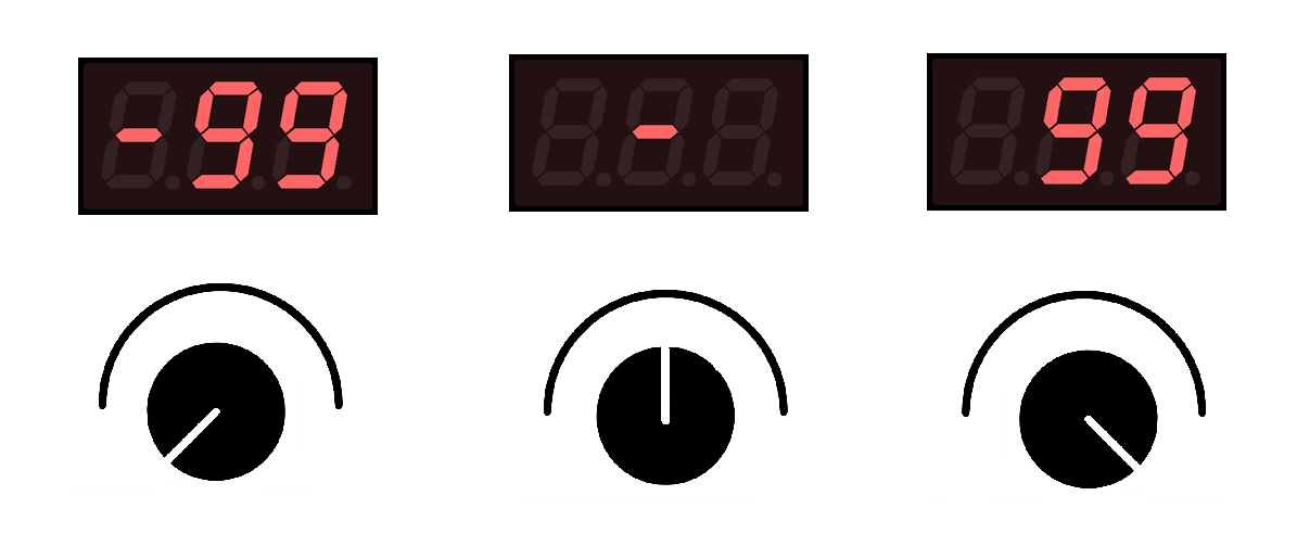
I have been working on my layout for my 3 digit 7 segment displays i have ordered.
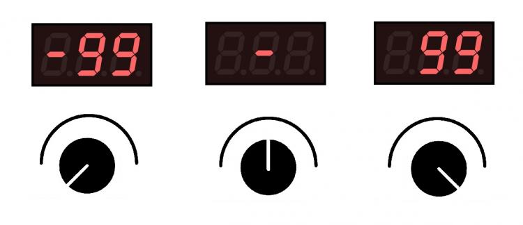
The values shown by my plugin are not the usual 0-127, what i need are.
if you move the pot all the way to the left its max value is -99
if you move the pot to the far right max value is 99
with the centre value being 0, or in this case just the centre line of the mide segment digit 2
this picture hopefully explains it better.
I am trying to get to grips with the matrix information, i understand the connection pdf on the dout boards as i have used them before.
I am also stuck on this section here:
DOUT_MATRIX n=1 rows=8 sr_dout_r1=1 inverted_row=0 mirrored_row=0 sr_dout_sel1=2 inverted_sel=0
DOUT_MATRIX n=2 rows=8 sr_dout_r1=3 inverted_row=0 mirrored_row=0 sr_dout_sel1=4 inverted_sel=0dout_matrix n=1 (this is the first matrix/sr) rows=8 (are the first 8 pins?), sr_dout_r1=1 (this is shift register 1) the common cathode is on the next section so this is shown is sr_dout_sel1=2 if i am correct.
i dont understand the syntax in this though, can someone explain it for me and i can then carry on writing the rest of the code
thanks
-
ok so the first section is as follows:
RESET_HW
LCD "%CLED Digit Demo"
# HW definitions for "Common Cathode" Digits
# see also http://www.ucapps.de/midibox_ng/mbng_led_digits_5x7bit.pdf as a reference(I am working on this section)
DOUT_MATRIX n=1 rows=8 sr_dout_r1=1 inverted_row=0 mirrored_row=0 sr_dout_sel1=2 inverted_sel=0
DOUT_MATRIX n=2 rows=8 sr_dout_r1=3 inverted_row=0 mirrored_row=0 sr_dout_sel1=4 inverted_sel=0# for "Common Anode" set inverted_row=1 and inverted_sel=1
# if the segment connections are mirrored, set mirrored_row=1# the digits are accessible with:
Dout 1
# first matrix: LED_MATRIX:1 ... LED_MATRIX:8
# second matrix: LED_MATRIX:17 .. LED_MATRIX:24Dout 2
# third matrix: LED_MATRIX:25 ..LED_MATRIX:32
# forth matrix: LED_MATRIX:41 ..LED_MATRIX:49Dout 3
# fifth matrix: LED_MATRIX:58 ..LED_MATRIX:65
# sixth matrix: LED_MATRIX:74 ..LED_MATRIX:81Dout 4
# seventh matrix LED_MATRIX:90 ..LED_MATRIX:97
# eighth matrix LED_MATRIX:106 ..LED_MATRIX113Hopefully I got that right as I would be using 4 Dout modules, I can carry on designing a set of pcbs in altium next week and get them made to mount the 7 seg lcds and the potentiometers
-
bloomin eck... i am even understanding the code in the link: midibox_ng_v1/cfg/tests/leddig1.ngc
I am going to write a version of that later and post it up, I am not expecting it to be perfect and it may need correcting i dare say but if I am in the right direction it is a start.
-
ok question one, im pretty sure i know the answer but here goes..
Q~ the pdf shows 5 x 3 digit displays, for 16 i would only need 4 per dout matrix, so I would link 4 douts with 4 x 3 digit displays to the core/ng and amend the code to reflect this?
also mapping an encoder or pot to each display and its value of 0-127 in the code also its event type and id etc?
-
Aha!! did not know about that.. I am going to have a read up on this, most likely will ask a few questions along the way, but this is the direction i want to go with this one controller. many thanks as always!

understanding the .ngc code
in MIDIbox NG
Posted
I am sat here trying a few things out, i have two buttons in the breadboard and I am writing test lines of code as i go along, everything i have already learned i have applied and they are working , I am going to try to work out the code for these two buttons and try it, if i dont get it, then i will post up what i have done and if anyone can help me out then I will ask.
thanks