

ssp
-
Posts
659 -
Joined
-
Last visited
-
Days Won
4
Content Type
Profiles
Forums
Blogs
Gallery
Posts posted by ssp
-
-
1 hour ago, latigid on said:
sr_dout_r1= is for 8x matrices
sr_dout_r2= is for 16x matricesI suppose you only use 8x8 matrices, thus keep sr_dout_r1 for the second DOUT.
Here's how you address one DOUT PCB:
sr_dout_r1=1
sr_dout_r1=2
sr_dout_r1=3
sr_dout_r1=4and here's how you address the next DOUT:
sr_dout_r1=5
sr_dout_r1=6
..I thought it was but, the manual isn't specific at that point so I wanted to check. I will give it a run later.
I assume the DOUT_MATRIX n= also changes?
DOUT_MATRIX n=1 rows=8 sr_dout_r1=1 inverted_row=0 mirrored_row=0 sr_dout_sel1=2 inverted_sel=0
DOUT_MATRIX n=2 rows=8 sr_dout_r1=3 inverted_row=0 mirrored_row=0 sr_dout_sel1=4 inverted_sel=0
DOUT_MATRIX n=3 rows=8 sr_dout_r1=5 inverted_row=0 mirrored_row=0 sr_dout_sel1=6 inverted_sel=0
DOUT_MATRIX n=4 rows=8 sr_dout_r1=7 inverted_row=0 mirrored_row=0 sr_dout_sel1=8 inverted_sel=0Also!! on the old core8 i could connect 4 doutx4 can you connect 4 to the mb_ng??
-
Dout question just wondering if this is right:
If i connect two dout pcbs then this works fine for the first one
DOUT_MATRIX n=1 rows=8 sr_dout_r1=1 inverted_row=0 mirrored_row=0 sr_dout_sel1=2 inverted_sel=0
is this correct for a second connected dout?
DOUT_MATRIX n=2 rows=8 sr_dout_r2=1 inverted_row=0 mirrored_row=0 sr_dout_sel2=2 inverted_sel=0Dout pcb 2 pins start from 33 - 64
so should the next section for the led matrix be?
EVENT_LED_MATRIX id=33 fwd_id=LED_MATRIX:34 led_matrix_pattern=Digit1 fwd_to_lcd=1 type=CC chn= 1 cc= 16 lcd_pos=1:1:2 label="1:%3d%B"
EVENT_LED_MATRIX id=34 fwd_id=LED_MATRIX:35 led_matrix_pattern=Digit2
EVENT_LED_MATRIX id=35 led_matrix_pattern=Digit3I am going to make another dout pcb tomorrow to test this anyway. I see in the manual it says this:
sr_dout_r2=<0..16> sets the (optional) second dout shift register of the led matrix row
sr_dout_sel2=<0..16> set to 0 if second is not required.
-
Just now, latigid on said:
POIDH!
I just hooked up a second 3 digit and moved the encoder over as well. it worked first time, the second 3 digit is just linked to the first on the row pins and the commons to the next 3 on the sel pins.
RESET_HW
LCD "Single CLED 3 Digit"
DOUT_MATRIX n=1 rows=8 sr_dout_r1=3 inverted_row=0 mirrored_row=0 sr_dout_sel1=4 inverted_sel=0
ENC n= 1 sr=1 pins=0:1 type=non_detented
ENC n= 2 sr=1 pins=2:3 type=non_detentedEVENT_ENC id=1 fwd_id=LED_MATRIX:1 type=CC chn= 1 cc= 16
EVENT_ENC id=2 fwd_id=LED_MATRIX:4 type=CC chn= 1 cc= 17EVENT_LED_MATRIX id=1 fwd_id=LED_MATRIX:2 led_matrix_pattern=Digit1 fwd_to_lcd=1 type=CC chn= 1 cc= 16 lcd_pos=1:1:2 label="1:%3d%B"
EVENT_LED_MATRIX id=2 fwd_id=LED_MATRIX:3 led_matrix_pattern=Digit2
EVENT_LED_MATRIX id=3 led_matrix_pattern=Digit3
EVENT_LED_MATRIX id=4 fwd_id=LED_MATRIX:5 led_matrix_pattern=Digit1 fwd_to_lcd=1 type=CC chn= 1 cc= 17 lcd_pos=1:1:2 label="2:%3d%B"
EVENT_LED_MATRIX id=5 fwd_id=LED_MATRIX:6 led_matrix_pattern=Digit2
EVENT_LED_MATRIX id=6 led_matrix_pattern=Digit3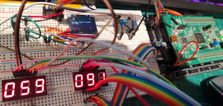
now i see it I can't unsee it!!
-
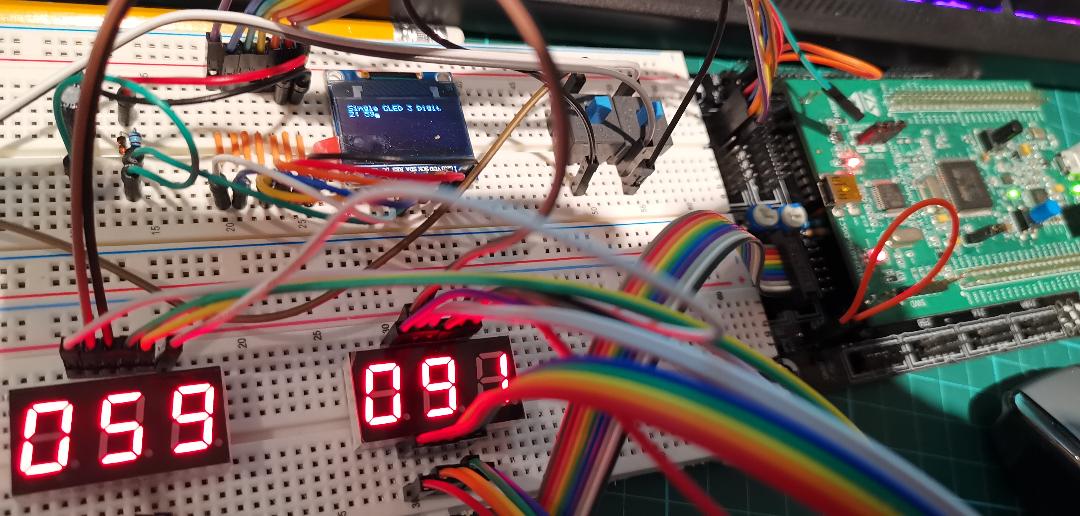
Encoder all hooked up and forwarding to the 3 digit display and the oled display!! cookie for me tonight!
RESET_HW
LCD "Single CLED 3 Digit"
DOUT_MATRIX n=1 rows=8 sr_dout_r1=3 inverted_row=0 mirrored_row=0 sr_dout_sel1=4 inverted_sel=0
EVENT_LED_MATRIX id=1 fwd_id=LED_MATRIX:2 led_matrix_pattern=Digit1 fwd_to_lcd=1 type=CC chn= 1 cc= 16 lcd_pos=1:1:2 label="1:%3d%B"
EVENT_LED_MATRIX id=2 fwd_id=LED_MATRIX:3 led_matrix_pattern=Digit2
EVENT_LED_MATRIX id=3 led_matrix_pattern=Digit3ENC n= 1 sr=1 pins=0:1 type=non_detented
EVENT_ENC id=1 fwd_id=LED_MATRIX:1 type=CC chn= 1 cc= 1
-
I am pleased to say that I finally understand the dout matrix syntax and structure for what i want., I am going to have a play with it now but this is a single 3 digit lcd on a doutx4 on the first shift register.
RESET_HW
LCD "Single CLED 3 Digit"
DOUT_MATRIX n=1 rows=8 sr_dout_r1=1 inverted_row=0 mirrored_row=0 sr_dout_sel1=2 inverted_sel=0
EVENT_LED_MATRIX id=1 fwd_id=LED_MATRIX:2 led_matrix_pattern=Digit1 fwd_to_lcd=1 type=CC chn= 1 cc= 16 lcd_pos=1:1:2 label="1:%3d%B"
EVENT_LED_MATRIX id=2 fwd_id=LED_MATRIX:3 led_matrix_pattern=Digit2
EVENT_LED_MATRIX id=3 led_matrix_pattern=Digit3My code, all is good, I changed the code so it moves to the 3rd shift register and the commons on sr=4
RESET_HW
LCD "Single CLED 3 Digit"
DOUT_MATRIX n=1 rows=8 sr_dout_r1=3 inverted_row=0 mirrored_row=0 sr_dout_sel1=4 inverted_sel=0
EVENT_LED_MATRIX id=1 fwd_id=LED_MATRIX:2 led_matrix_pattern=Digit1 fwd_to_lcd=1 type=CC chn= 1 cc= 16 lcd_pos=1:1:2 label="1:%3d%B"
EVENT_LED_MATRIX id=2 fwd_id=LED_MATRIX:3 led_matrix_pattern=Digit2
EVENT_LED_MATRIX id=3 led_matrix_pattern=Digit3ALL IS GOOD!!! my brain worked today. I am just reading how to forward from an encoder to this event now. wish me luck!!
Many thanks to latigid-on for his patience and help so far.
-
My brain may have clicked today, not 100% sure yet but I sat talking the code to myself and it started making sense. Will post some up later after trying it or vice versa...
-
Look at that, even the things I thought I knew were wrong!! I never cease to amaze myself
-
2 hours ago, latigid on said:
Could be anything from incomplete NGC file, dodgy breadboard or wiring, corrupt SD card (saving often doesn't work well, upload always worked better for me) etc. etc.
Draw a functional map of how it should work and see if you connected the dots properly. Adapt the NGC file to suit your hardware and again just playing with it might help.
I have buzzed all of the cables to and from the breadboard, checked the dout pcb, (i even soldered a new one up and changed out all the sr's on the old one) all is good connectivity wise. I am trying hard to understand this, What i have done is create a test.ngc file on my sd card and i run all my test code from that in mios studio, same as the first steps examples did. most of the things i have done since starting to learn i have done this way and have worked.
I dont hide the fact i am not a coder and where it gets more complex i struggle yet, i push on but yes i know its annoying I have to ask questions along the way but I dont expect anyone to do do the work for me.
I work off examples, that way i can try it, figure it out by messing with it and hey presto it clicks, like the padding and syntax for the lcd's and oleds. It took a while but after playing with the examples and trying a few modifications it all clicked and I understood it all, the same with mapping potentiometers and encoders etc and their types, values etc. i have all of that down and i use it fine.
I just need to figure out the matrix syntax etc and as soon as i do.. it will click.
for example:
n=<1..8>Specifies the matrix number which should be configured; it can range from 1..8 ( this i dont understand)
rows=<4|8|16>Sets the number of rows which should be scanned: (this i dont understand)
This is think I understand
sr_dout_sel1=<0..16> Sets the first DOUT shift register which should output the row selection signals ( if this =1 then this means the 7 segments goto sr=1)
sr_dout_r1=<0..16>Sets the first DOUT shift register of the LED matrix row. (if r1=1 then the first shift register on the doutx4 pcb is number 1)
Where do i assign the common cathodes? as they would link to J4 the second shift register that has no pullup resistors in just bridges.
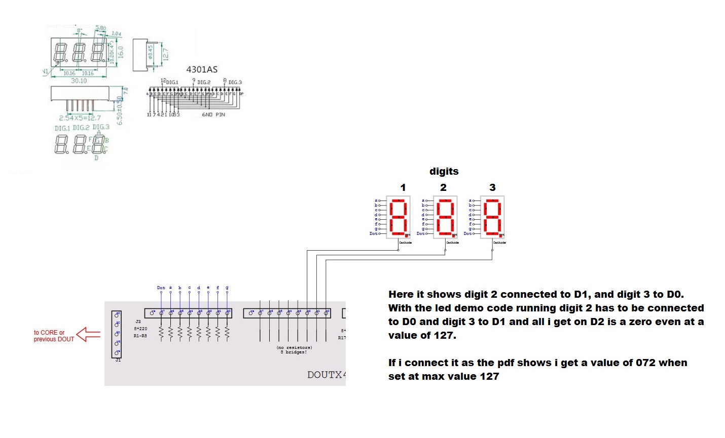
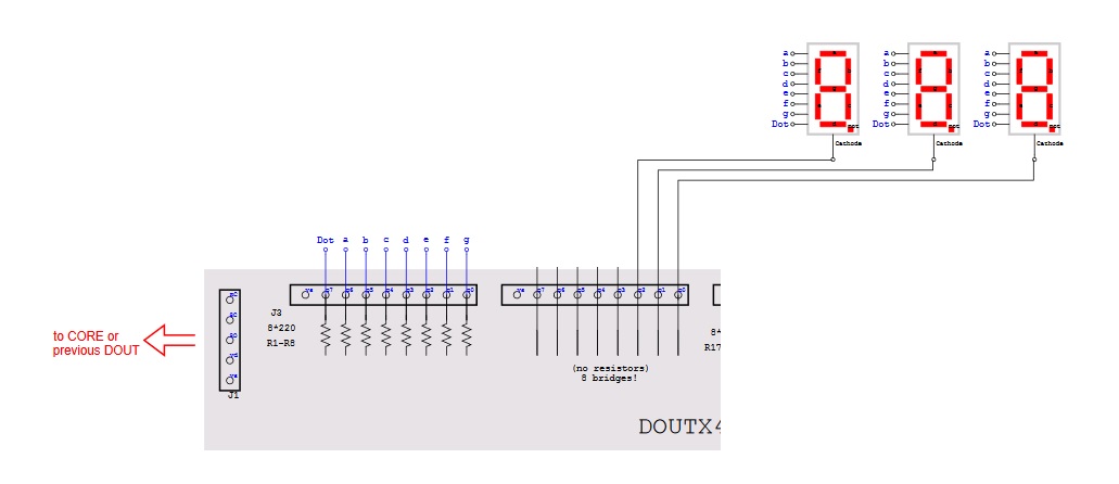
I also looked at this schematic and it blew my mind!! http://ucapps.de/mbhp/mbhp_blm_map.pdf
-
spent some time on this but for some reason it eludes me, i cannot put the pieces together. I really want to figure this out but its like using a flower to puch a hole through a brick wall on times.
I know how a dout works, i understand the pins out on the first and the cathodes on the second sr, etc. but when i try to put it all together in the code it doesnt work.
how is it i can understand most of it already but this is just not sticking or making sense...
-
24 minutes ago, latigid on said:
Define the shift registers connected to the "sel" and "dout" parts, at the moment they all = 0 and so no data are sent.
Ok, but in this case with the disco connection to mios studio and just running the lcd test code from there I get some of the (cc#16 and 17 work fine with the 3 digits going from 0-127) should that even happen?
I used clean flashed disco board, then mbng installed, open mios studio and create a test. Ngc file. Then I selected edit text, pasted in the led test code, save. The 3 digit lit up and I moved mios studio cc18 slider. Some worked some didn't.
I will have to read the relevant sections again tomorrow and try the code on one 3 digit and see what happens.
-
Looking in my .ngc file i see the dout matrix hardware section, i notice that everything is pretty much the same, do i need to edit this section to reflect the code in the led test?
# DOUT_MATRIX hardware
DOUT_MATRIX n=1 rows=8 inverted_sel=0 inverted_row=0 mirrored_row=0 \
sr_dout_sel1= 0 sr_dout_sel2= 0 sr_dout_r1= 0 sr_dout_r2= 0 sr_dout_g1= 0 sr_dout_g2= 0 sr_dout_b1= 0 sr_dout_b2= 0
DOUT_MATRIX n=2 rows=8 inverted_sel=0 inverted_row=0 mirrored_row=0 \
sr_dout_sel1= 0 sr_dout_sel2= 0 sr_dout_r1= 0 sr_dout_r2= 0 sr_dout_g1= 0 sr_dout_g2= 0 sr_dout_b1= 0 sr_dout_b2= 0
I didnt put all of it in here to keep it simple.in the led digit demo it shows this
# Control 5x3 LED Digits to output 7bit values
RESET_HW
LCD "%CLED Digit Demo"
# HW definitions for "Common Cathode" Digits
# see also http://www.ucapps.de/midibox_ng/mbng_led_digits_5x7bit.pdf
DOUT_MATRIX n=1 rows=8 sr_dout_r1=1 inverted_row=0 mirrored_row=0 sr_dout_sel1=2 inverted_sel=0
DOUT_MATRIX n=2 rows=8 sr_dout_r1=3 inverted_row=0 mirrored_row=0 sr_dout_sel1=4 inverted_sel=0the led digit demo has the DOUT_MATRIX n=1 defined, but my ngc file doesnt, do i need to edit the ngc in the same way?
-
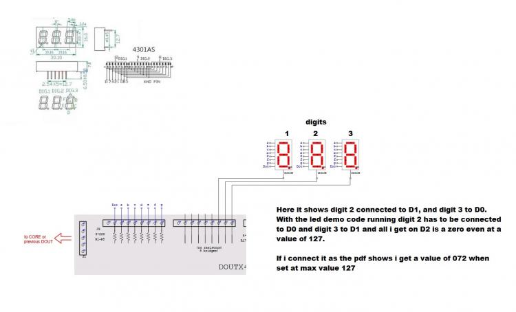
I have spent all day trying to figure this out rather than have to ask for help again, i have the data sheet for the digits and i checked them with my meter ( i know how to do this and how to use them having built my midimon years ago on a core8)
if you look at the pdf : http://ucapps.de/midibox_ng/mbng_led_digits_5x7bit.pdf
i connected one 3 digit display as the top three show
i then sent the code: https://github.com/midibox/mios32/blob/master/apps/controllers/midibox_ng_v1/cfg/tests/leddig1.ngc to the disco board
as i state above: using the connection diagram on the pdf for the top three digits on the right of the pdf
on J4 using #CC18
D0 = DIGIT 2 ( this should be as the diagram D1)
D1 - DIGIT 3 (this should be as the diagram D0)D2 = Digit 1 ( this only shows a zero, when the value is increased to 127, it remains at zero even though the 27 are shown on the other digits)
On the PDF file is this statement: The "Common" connections (selection lines) arefree assignable in the .NGR file!Feel free to change the order (e.g. due to layout reasons)
What .NGR file? there is no link or reference to this.
I am steadily learning as I go and messing with code running to see what it does, some of this I am having a really hard time understanding, I am trying not to have to ask for help, but after 1 or 2 days of going nowhere I have no choice.
I have looked for an example or suggestion on how to forward an pot to a 3 digit led all over the site but not really found anything that i can get an idea from and try, modifying the code as i go.
-
still scratching my head on this one, would be something if nothing was working!! im sure this is trying to tease me! lol
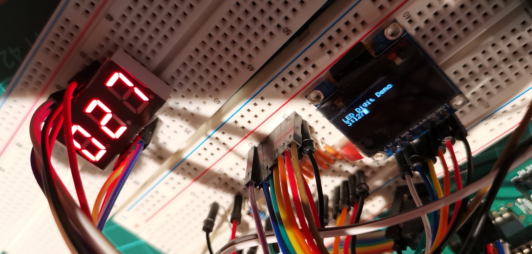
this is one signle dout connected to the mb-ng, using J3, the cathodes are on J4 connected as i stated earlier and it still doesnt show digit 1, the value is as the oled shows 127

-
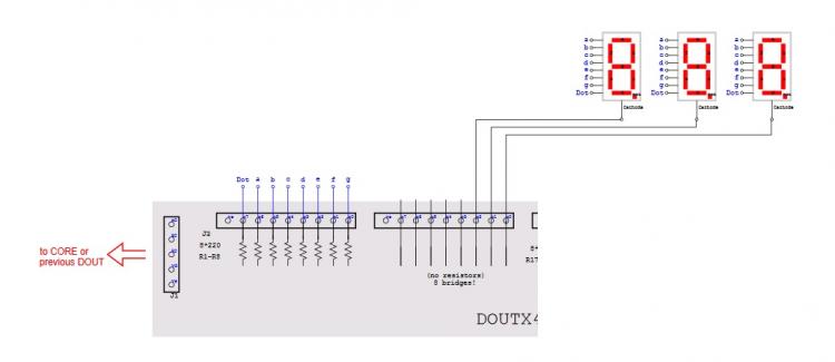
Having an issue with the led digit demo.
in the code it says this:
RESET_HW
LCD "%CLED Digit Demo"
# HW definitions for "Common Cathode" Digits
# see also http://www.ucapps.de/midibox_ng/mbng_led_digits_5x7bit.pdf
DOUT_MATRIX n=1 rows=8 sr_dout_r1=1 inverted_row=0 mirrored_row=0 sr_dout_sel1=2 inverted_sel=0
DOUT_MATRIX n=2 rows=8 sr_dout_r1=3 inverted_row=0 mirrored_row=0 sr_dout_sel1=4 inverted_sel=0# for "Common Anode" set inverted_row=1 and inverted_sel=1
# if the segment connections are mirrored, set mirrored_row=1yet in the picture pdf it says this: http://ucapps.de/midibox_ng/mbng_led_digits_5x7bit.pdf
7 Segment LED Digits --- Common Cathode (inverted_sel=1, inverted_row=1)
Also if i wire in the 3 digit displays as shown in the pdf the pins for the matrix that runs on #cc 18 using one dout pcb and the digits are connected to J3 and the cathodes J4 ( as the pdf shows)
the pdf shows that digit 3 goes to D0 however on mine when connected it goes to D1 and shows digit 2 goes to D1 when connected D0 to display correctly, if i move the slider in mios they respond fine these are on
Digit 1 has no pick up on the dout for some reason.
it also says this on the pdf:
The "Common" connections (selection lines) arefree assignable in the .NGR file!Feel free to change the order (e.g. due to layout reasons)
There is no reference to any .ngr file with this led digit demo for me to edit.
With one dout x 4 connected here are the pins i have running
on J6 using #CC16
D5 = DIGIT 1
D6 = DIGIT 2
D7 = DIGIT 3on J6 using #CC17
D2 = DIGIT 1
D3 = DIGIT 2
D4 = DIGIT 3on J4 using #CC18
D0 = DIGIT 2
D1 - DIGIT 3Digit 1 has no connection point on J4 however when the slider for #cc18 is all the way upto 127, the number 27 on digits 2+3 are present.
now for this to work, the common cathodes on J6 are hooked up but the digits are connected to j3, if connected to j5 there is nothing.
-
I see in some other threads that exec_meta can be used, so I wil ltake a look at that today as well.
-
14 hours ago, Zam said:
Hello
The purpose is to have on up and one down button cycle trigging 0 21 41 61 81 with dedicated led for each steps right ?
Maybe a script(runsection + .NGR) will be better strategy, especially to retrigg/update the "opposit" button value to match actual CC value
Otherwise you push button 1 few time (let say 2, CC val=61) but button 2 stay at 0, and if you push it once you send 21...
Best
Zam
Thanks Zam I will take a look at this today, the buttons work with the leds, I was able to understand that and get it working after a few changes. I still have a lot to read and learn, having a quiet day to day so I am going to play around with some other code as well.
Thanks again!
Si
-
I cant seem to get around the repeated values.
the ranges work with the button presses but once you get to say 81, then press the other button to go back down the values it repeates the value 81 instead of just going to 61. is there something i need to put in to stop this repeat?
thanks
-
ok leds working but sometimes two are on at the same time, gotta figure this out ;)
ok all sorted, leds working in sequence now, i still have the issue where you get to 81, res the down and it is 81 again then 61 same from 0 upwards.
edited the code
RESET_HW
# the used maps:
MAP1 81 61 41 21 0
MAP2 0 21 41 61 81# define a radio group with a single toggle button but multiple LEDs
EVENT_BUTTON id= 1 fwd_to_lcd=1 type=CC chn=1 cc=16 button_mode=Toggle range=map1 radio_group=2 lcd_pos=1:1:1 label="Transpose- %3d"
EVENT_BUTTON id= 2 fwd_to_lcd=1 type=CC chn=1 cc=16 button_mode=Toggle range=map2 radio_group=1 lcd_pos=1:1:1 label="Transpose+ %3d"# Note: the map will only be considered if a button is configured for button_mode=Toggle !
# these LEDs are mapped to radio_group1 and radio_group2, and therefore will get an "automatic feedback" whenever the toggle button changes the value (or receives a new value)
#This is for the transpose minus button
EVENT_LED id= 1 range=0:0 radio_group=2
EVENT_LED id= 2 range=21:21 radio_group=2
EVENT_LED id= 3 range=41:41 radio_group=2
EVENT_LED id= 4 range=61:61 radio_group=2
EVENT_LED id= 5 range=81:81 radio_group=2#This is for the transpose plus button
EVENT_LED id= 5 range=81:81 radio_group=1
EVENT_LED id= 4 range=61:61 radio_group=1
EVENT_LED id= 3 range=41:41 radio_group=1
EVENT_LED id= 2 range=21:21 radio_group=1
EVENT_LED id= 1 range=0:0 radio_group=1 -
led is now working (single) I am just going to fit the rest , link them on the dout to breadboard and test.
-
ok the code works ;) I havent hooked up the leds yet, will do shortly. This is the code I used.
RESET_HW
# the used maps:
MAP1 81 61 41 21 0
MAP2 0 21 41 61 81# define a radio group with a single toggle button but multiple LEDs
EVENT_BUTTON id= 1 fwd_to_lcd=1 type=CC chn=1 cc=16 button_mode=Toggle range=map1 radio_group=1 lcd_pos=1:1:1 label="Transpose- %3d"
EVENT_BUTTON id= 2 fwd_to_lcd=1 type=CC chn=1 cc=16 button_mode=Toggle range=map2 radio_group=2 lcd_pos=1:1:1 label="Transpose+ %3d"# Note: the map will only be considered if a button is configured for button_mode=Toggle !
# these LEDs are mapped to radio_group1 and radio_group2, and therefore will get an "automatic feedback" whenever the toggle button changes the value (or receives a new value)
#This is for the transpose minus button
EVENT_LED id= 1 range=41:41 radio_group=1
EVENT_LED id= 2 range=21:21 radio_group=1
EVENT_LED id= 3 range=0:0 radio_group=1#This is for the transpose plus button
EVENT_LED id= 4 range=41:41 radio_group=2
EVENT_LED id= 5 range=61:61 radio_group=2
EVENT_LED id= 6 range=81:81 radio_group=2What I have noticed in Mios is that the 0 repeats itself on a button press after reaching 0 i then press the button to go upto 21, but it gives a 0 then a 21. the same with 81 going back to 0
[1649.779] b0 10 51 Chn# 1 CC# 16 = 81
[1650.606] b0 10 3d Chn# 1 CC# 16 = 61
[1651.496] b0 10 29 Chn# 1 CC# 16 = 41
[1652.177] b0 10 15 Chn# 1 CC# 16 = 21
[1652.676] b0 10 00 Chn# 1 CC# 16 = 0
[1654.563] b0 10 15 Chn# 1 CC# 16 = 21
[1655.289] b0 10 29 Chn# 1 CC# 16 = 41
[1655.776] b0 10 3d Chn# 1 CC# 16 = 61
[1656.337] b0 10 51 Chn# 1 CC# 16 = 81
[1656.972] b0 10 51 Chn# 1 CC# 16 = 81
[1657.790] b0 10 3d Chn# 1 CC# 16 = 61
[1658.428] b0 10 29 Chn# 1 CC# 16 = 41
[1659.089] b0 10 15 Chn# 1 CC# 16 = 21
[1659.853] b0 10 00 Chn# 1 CC# 16 = 0
[1660.565] b0 10 00 Chn# 1 CC# 16 = 0
[1661.122] b0 10 15 Chn# 1 CC# 16 = 21
[1661.623] b0 10 29 Chn# 1 CC# 16 = 41
[1662.162] b0 10 3d Chn# 1 CC# 16 = 61
[1662.745] b0 10 51 Chn# 1 CC# 16 = 81
[1663.645] b0 10 51 Chn# 1 CC# 16 = 81
[1664.287] b0 10 3d Chn# 1 CC# 16 = 61
[1664.727] b0 10 29 Chn# 1 CC# 16 = 41
[1665.045] b0 10 15 Chn# 1 CC# 16 = 21
[1665.486] b0 10 00 Chn# 1 CC# 16 = 0
[1666.271] b0 10 00 Chn# 1 CC# 16 = 0
[1666.726] b0 10 15 Chn# 1 CC# 16 = 21
[1667.069] b0 10 29 Chn# 1 CC# 16 = 41
[1667.340] b0 10 3d Chn# 1 CC# 16 = 61
[1667.821] b0 10 51 Chn# 1 CC# 16 = 81
[1668.394] b0 10 51 Chn# 1 CC# 16 = 81
[1668.832] b0 10 3d Chn# 1 CC# 16 = 61
[1669.152] b0 10 29 Chn# 1 CC# 16 = 41
[1669.445] b0 10 15 Chn# 1 CC# 16 = 21
[1670.023] b0 10 00 Chn# 1 CC# 16 = 0It also has a a random value jump somtimes as shown here am i missing something to stop this?
[2100.260] b0 10 29 Chn# 1 CC# 16 = 41
[2100.671] b0 10 15 Chn# 1 CC# 16 = 21
[2101.061] b0 10 00 Chn# 1 CC# 16 = 0
[2101.457] b0 10 3d Chn# 1 CC# 16 = 61
[2101.706] b0 10 51 Chn# 1 CC# 16 = 81
[2101.976] b0 10 00 Chn# 1 CC# 16 = 0
[2102.215] b0 10 15 Chn# 1 CC# 16 = 21
[2102.521] b0 10 29 Chn# 1 CC# 16 = 41
[2102.819] b0 10 3d Chn# 1 CC# 16 = 61 -
5 hours ago, FantomXR said:
Again: look at the MAP feature. This exactly what you need.
Set a map as range with range=Map1 and create a map with the desired values underneath it.
See this example:
https://github.com/midibox/mios32/blob/master/apps/controllers/midibox_ng_v1/cfg/tests/mapbtn.ngc
I swear I am going nuts you know, i posted this earlier in my thread as well... thanks for the heads up Fantom.
Ok so I managed to grab 5 mins to do this, will test it later
two buttons each with its own #cc by using the button_mode OnOff if the transpose + is all the way to the highest value , pressing the transpose - will take the value lower as it already sees the higher value as stated here:
# a button which doesn't toggle, but just turns on/off
# in this case either the lowest or highest item of a map will be taken
So I have edited my code to come up with this:
LCD "%CMap Button Values"# the used maps:
MAP1 41 21 0
MAP2 41 61 81#I can also have a full range but reversed on both:
MAP1 81 61 41 21 0
MAP2 0 21 41 61 81# define a radio group with a single toggle button but multiple LEDs
EVENT_BUTTON id= 1 fwd_to_lcd=1 type=CC chn=1 cc=16 button_mode=OnOff range=map1 radio_group=1 lcd_pos=1:1:1 label="^Transpose-"
EVENT_BUTTON id= 2 fwd_to_lcd=1 type=CC chn=1 cc=16 button_mode=OnOff range=map2 radio_group=2 lcd_pos=1:1:1 label="^Transpose+"# Note: the map will only be considered if a button is configured for button_mode=Toggle !
# these LEDs are mapped to radio_group1 and radio_group2, and therefore will get an "automatic feedback" whenever the toggle button changes the value (or receives a new value)
#This is for the transpose minus button
EVENT_LED id= 1 range=41:41 radio_group=1
EVENT_LED id= 2 range=21:21 radio_group=1
EVENT_LED id= 3 range=0:0 radio_group=1#This is for the transpose plus button
EVENT_LED id= 4 range=41:41 radio_group=2
EVENT_LED id= 5 range=61:61 radio_group=2
EVENT_LED id= 6 range=81:81 radio_group=2looking forward to trying this after work
-
I didnt manage to get the buttons to step to values i wanted. Everything I tried if i press the increase value it would gotot "2" then back to "1" or "0". It wouldnt go higher than that.
It must be possible for example, the Dimmed=1 command will dim an led by values of 16 so this must be possible for the buttons to send out a cc~ with value steps of 20.
Can anyone point me in the right direction please?
-
Got a few things working but not there yet

-
 1
1
-
-
I am sat here trying a few things out, i have two buttons in the breadboard and I am writing test lines of code as i go along, everything i have already learned i have applied and they are working , I am going to try to work out the code for these two buttons and try it, if i dont get it, then i will post up what i have done and if anyone can help me out then I will ask.
thanks
multiple Clcd's
in MIDIbox NG
Posted
I thought it was but, the manual isn't specific at that point so I wanted to check. I will give it a run later. Tx
EDIT: Ok looking through some old threads I see that it is n=1/2/3/4 etc. I'm good there.