fussylizard
-
Posts
280 -
Joined
-
Last visited
Content Type
Profiles
Forums
Blogs
Gallery
Everything posted by fussylizard
-
Where to buy MB-6582 Control surface parts
fussylizard replied to pingosimon's topic in Parts Archive
Grizz just PM'ed me about parts from SmashTV so you can add to the above Mouser list the following from SmashTV's shop: - 1 x base PCB - 1 x base parts kit - 1 x control surface PCB - 1 x 2 pin header for the fan - 8 x 8 pin headers for the CS to Base PCB if you use right-angle headers like I did (highly recommended) - 1 x 2 pin header for the CS to Base PCB if you use right-angle headers like I did (highly recommended) - 1 x 16 pin header (2x8) for the LCD - Ribbon cable for LCD and base PCB to CS (I would get 4 feet or so) - 8 x 3 pin headers for the feedback pots - 1 x 2 pin header for the mini phono ("complete mix") jack - 1 x 2 pin header for the power LED on the back panel If anyone notices anything missing please let me know and I'll amend this post. Thx, C -
Not enough drum loops??! Time to hit the sample CD stores. :-) Though these days I usually roll my own from individual hits, with the occasional hi hat loop or something. That works great for dance-y stuff that I like. I also recently got Audio Damage's new drum synth Tattoo which is loads of fun, and I just got it outputting MIDI to my 888. Good times ahead on the drum front!
-
Just gave it a listen and I like it, esp. the percussion, the melody starting around 1:45 (SID I'm assuming?), and the arp starting around 3:15. I need to knock out a few songs myself, it's been too long w/ work, bulk orders, MB-SEQ, etc. BTW I just got Ableton myself. It won't replace my beloved FL Studio but I was so jealous of baconjuice's monome in our last jam session that I got a Launchpad, and ended up getting Live to go w/ it. If you get Max 4 Live + a Launchpad you can get Novation's sequencer app that totally rocks. I'd love to tweak it to work w/ the MB-6582 bassline sequencer (may have to hack in some firmware changes so I can control steps from MIDI), but time is limited. Darn that irritating little thing called work... Anyway, nice work and thx for sharing!
-
Not sure where you are located but here's a post with a list of Mouser part numbers that you might find helpful: (I really need to add this info to the wiki...) You will also need some bolts, nuts, etc. I assume you've seen the wiki page for the project which has all the info: http://www.midibox.org/dokuwiki/doku.php?id=wilba There is a parts page that should answer most questions. The PCBs are well labeled so it is a relatively easy build. Just go in stages as directed in the build guide and actually do the tests at each step. Trust me, this will make your life much easier. And don't insert your SIDs until everything else is solid. You don't want to risk frying those not-so-easily-replaced parts. Have fun and post questions if you get stuck. Regards, C
-
FYI I'm doing the same w/ my MB-SEQ. I'm (slowly) working on a case design for this as well based on an off-the-shelf Hammond case (http://www.hammondmfg.com/pdf/1456RH3.pdf). I'll let you know if I come across anything interesting in my build. I also plan to have an internal power supply for both the MB-SEQ and the AOUT_NG based on the design used in the MB-808.
-
Do you get MIDI from the first core? I would pull out all chips (SIDs, control surface ICs, etc.) except for the first core and check the MIDI I/O using MIOS Studio. If you have a standalone, known-working core PCB you can test the LCD there to ensure everything it is wired correctly, etc. Did you use headers to connect the base PCB to the CS PCB? If so, I would focus on the base board first, then when everything looks good there add in the CS PCB.
-
That sounds like it would work on the MB-6582 side. I'd have to check the schematic to be sure, but it should be OK. One problem you might run into is with your bipolar PSU. I'm no expert, but I've read that some bipolar power supply designs do not work well when you try to pull more current off the positive supply than the negative supply. I use a Paia +/- 12V power supply for MB-FM. I tried pulling +5V off the +12V side and it didn't work correctly. May have been user error, etc. The Paia supply also uses a voltage doubler circuit which could have been a problem. You'll probably just have to try it and see if your supply works, doesn't get too hot, etc.
-
MB-SEQ V3/V4 Control Surface PCB and matching case
fussylizard replied to Wilba's topic in MIDIbox SEQ
There is a small (closed) bulk order going on now for the "bleeding edge prototypers". What this means is (a) you have to figure out your own case solution, and (b) you have limited build instructions, help, debugging info, etc. This bulk order is already closed, but if there are any spare boards I will post about it here once I devise the most unfair system possible for allocating spares, if any. :-) Once there is a full bulk order getting started, Wilba or someone will post here about it. Regards, C -
MB-SEQ V3/V4 Control Surface PCB and matching case
fussylizard replied to Wilba's topic in MIDIbox SEQ
I'm running Wilba's "Bleeding edge prototypers bulk order #2". If Wilba has confirmed your order you should have received an email from me on Dec. 22 explaining what you need to do. If you have a confirmed order from Wilba but have *not* received an email from me, please send me a message via the forum so I can ensure I get your order details. If I don't hear from you by Sunday, Jan. 10, I will assume you are no longer interested and will allocate your board to another buyer. BTW I believe all PCBs have been allocated to buyers at this time. If any spares become available, I'll post here and see if anyone is interested. :-) Thanks, C -
Make sure the wires from the Core to the OPL board are < 10 cm in length. Wilba had issues with longer lengths. I tried making a special cable to avoid soldering to the bottom side of the board but it was a pain to debug and the OPL was a bit temperamental. Soldering straight to the bottom of the core (like the instructions say!) seemed to work better. Good luck!
-
Did you cut vent slits in your case? I wonder what difference that would make. Per the zillions of pics I've posted, I have 7 or so slits cut right by the power supply section to (hopefully) give nice airflow across all the SIDs. I should probably take measurements but I've not opened up my MB in many months and don't really want to start... :-)
-
Just re-posted the pictures to the first post in this thread. To maximize heat transfer you should put a little heat sink compound on top of the SID before you slide on the heat sink. You don't need much. These heat sinks clip on very tightly so just put a thin coat in the middle of the chip and leave a few mm around the edge uncovered since it will get spread out by the heat sink. Don't overdo it. I bought a small tube of it at a local computer shop (intended for CPU heat sinks) for about $1. It took 2 tubes for 8 SIDs. If you're in the States you can order those same heat sinks from Electronic Precepts per my original post. They are not keen on doing international shipping so if you are outside the US just PM me and I can sell you some. I bought a bunch of extras last time I ordered specifically to help out the international folks but just haven't gotten around to posting anything about it. I forget how much they cost, but I think I got them for under $1 each since I bought them in bulk last time. They are probably unnecessary, but I don't want to chance it with my precious SIDs. :-)
-
I use something similiar (PCB cleaning fluid). I didn't have good luck with plain alcohol (99% might work though but is not as readily available), so I got a dedicated PCB flux cleaner in an aerosol can. I use a little hog-hair brush (from the same section of the same store that I bought the flux cleaner) to help since my can doesn't have a fancy brush attachment like Phil's. :-)
-
M-Audio Delta 1010LT and MIDIbox wierdness
fussylizard replied to Wilba's topic in Testing/Troubleshooting
Good to know. I have two of them. But what on earth drove you to update to Windows 7? :-) -
I had a question also - is it possible to have the forum keep me logged in? Pretty much every time I go to the site I have to go to the login screen and enter my userid and password. It was loads 'o fun the first 100 times, but now it's getting a little old. It seems like occasionally it remembers me, but maybe the timeout is really short like an hour or something. I have the "remember me" box checked on the login screen but I'm not sure it makes any difference. Thx, C
-
MB-SEQ V3/V4 Control Surface PCB and matching case
fussylizard replied to Wilba's topic in MIDIbox SEQ
I got confirmation from FPE today that they looked at the pics I posted of this Hammond case and they can machine both top surfaces and the rear panel as well. The extra clamping will incur an additional fee of ~US$15. I'm working on a panel layout now for the rear panel... -
Where to buy MB-6582 Control surface parts
fussylizard replied to pingosimon's topic in Parts Archive
BTW I used 2.2k resistors with those LEDs I posted. Of course you will need to change that if you use different LCDs. Yeah, I was trawling about that fan site and then discovered Mouser carried usable fans, so iNumSuppliersToHassleWith--; I ordered pretty much everything for mine from SmashTV, Mouser, and McMaster-Carr (for all the bolts and stuff). I think I attached the fan using bolts I already had and ordered everything else. -
When I was building my MB-6582 I had two of the regulators swapped and had to desolder them. The solder sucker and soldering braid didn't work very well. I ended up using some Chip Qwik (I got it from www.curious-inventor.com) and it worked a treat. For those of you who have not seen it before it is basically low-melting point solder. The idea is you heat up your part to be desoldered, then apply some Chip Qwik to the joint which mixes in and makes the solder stay soft longer. You then have enough time to quickly heat all 3 pins on the regulator and pull it out. Chip-Qwik is about $13 US for a small kit of it but worth having around for those tough jobs. The soldering video on Curious Inventor shows it being used IIRC.
-
Where to buy MB-6582 Control surface parts
fussylizard replied to pingosimon's topic in Parts Archive
I *really* need to post my parts list and update the wiki. I've been meaning to do this for ages. All of these parts were used with success in my MB-6582. Here's a partial list of what I used: Fan - 664-AD0405DB-G70-LF - Just a normal fan (no backlight). http://www.mouser.com/Search/ProductDetail.aspx?R=AD0405DB-G70-LFvirtualkey66400000virtualkey664-AD0405DB-G70-LF Fan guard - 562-08149 - Chromed http://www.mouser.com/Search/ProductDetail.aspx?R=08149virtualkey56210000virtualkey562-08149 10mm threaded spacers - 855-R30-1001002 http://www.mouser.com/Search/ProductDetail.aspx?R=R30-1001002virtualkey57420000virtualkey855-R30-1001002 Diodes - 512-1N4148T50A http://www.mouser.com/Search/ProductDetail.aspx?R=1N4148_T50Avirtualkey51210000virtualkey512-1N4148T50A Encoders - 318-ENC160F-24P http://www.mouser.com/Search/ProductDetail.aspx?R=RE160F-40E3-20A-24Pvirtualkey14860000virtualkey318-ENC160F-24P Tactile Switches - 688-SKHHDT http://www.mouser.com/Search/ProductDetail.aspx?R=SKHHDTA010virtualkey68800000virtualkey688-SKHHDT DB-25 connector - 571-5-747913-2 http://www.mouser.com/Search/ProductDetail.aspx?R=5-747913-2virtualkey57100000virtualkey571-5-747913-2 DB-25 mounting kit - 571-5207719-1 - You can use bolts you already have instead of this, but it's nice to just have the exact right parts. http://www.mouser.com/Search/ProductDetail.aspx?R=5207719-1virtualkey57100000virtualkey571-5207719-1 Feedback pots - 313-1250F-100K - 100k linear taper. You can use other values also. I also tried 500k audio taper but preferred these. You might try other values. These have a .25" shaft for knobs. http://www.mouser.com/Search/ProductDetail.aspx?R=RV122F-20-15F-B100Kvirtualkey14860000virtualkey313-1250F-100K Knobs for feedback pots - 450-2050-GRX These have a yellow top so you may want different knobs to match your color scheme. http://www.mouser.com/Search/ProductDetail.aspx?R=450-2050-GRXvirtualkey56100000virtualkey450-2050-GRX Stereo mix jack - 161-7300-EX http://www.mouser.com/Search/ProductDetail.aspx?R=161-7300-EXvirtualkey11180000virtualkey161-7300-EX 40-pin right-angle headers - 517-5111TG - If you want to use headers on your control surface board instead of soldering wires directly between the CS and base PCBs, these worked well for me (see my pics, link below). http://www.mouser.com/Search/ProductDetail.aspx?R=2340-5111TGvirtualkey51750000virtualkey517-5111TG 3mm LEDs - 604-WP7104SYD - These are yellow, but use whatever you like. Don't forget to get one for the rear panel power indicator! http://www.mouser.com/Search/ProductDetail.aspx?R=WP7104SYDvirtualkey60400000virtualkey604-WP7104SYD 20x4 LCD - CFAH2004A-YTI-JT - Yellow-on-black, but use whatever you like. This is a relatively expensive display but I love the way it looks. https://www.crystalfontz.com/product/CFAH2004AYTIJT.html Be careful with this list. Some of these are yellow which may not work with your color scheme, but hopefully they will be a useful reference. Also, with these LEDs I had to use larger resistors to get the brightness down to a good level. I don't have the # in front of me, but I can check after work and see what value I ended up using for this. I ended up using 2.2K resistors. Note these resistors are changed on the base PCB, not the control PCB. But you may prefer your LEDs to be brighter than me. :-) Here's some pics of my MIDIbox so you can see some of the parts I used: http://picasaweb.google.com/fussylizard/MB6582?authkey=Gv1sRgCM7npqbPgvbfYA&feat=directlink I'll try to put together a list of the other parts I used also since I also used a bunch of bolts and stuff plus a few other things (mostly headers/crimp pins) from SmashTV's shop. But now I'd better get working. :-) Good luck! -
Which diodes for the MB-6582 Control surface?
fussylizard replied to pingosimon's topic in MIDIbox SID
Here's what I have used with success: http://www.mouser.com/Search/ProductDetail.aspx?R=1N4148_T50Avirtualkey51210000virtualkey512-1N4148T50A -
MB-SEQ V3/V4 Control Surface PCB and matching case
fussylizard replied to Wilba's topic in MIDIbox SEQ
I think you are suggesting the following: - Get FPE to make a "standard" panel - Cut out a big hole in the case just smaller than the standard panel - Bolt/JB-Weld the standard panel to the case I have considered that, but I'm not sure how it would look overall, but yeah, it would probably be cheaper. I need to check it in Front Panel Designer. But it would allow for a nice anodized surface since I'm not in love with the powder coat (the powder coating is well done, I just prefer the look of the anodized aluminum). I was also thinking that the top flat area would be good for maybe putting 1/4" CV out jacks from an AOUT_NG or something (I assume I can sequence AOUT signals...need to double-check the manual). That would be super fun! -
MB-SEQ V3/V4 Control Surface PCB and matching case
fussylizard replied to Wilba's topic in MIDIbox SEQ
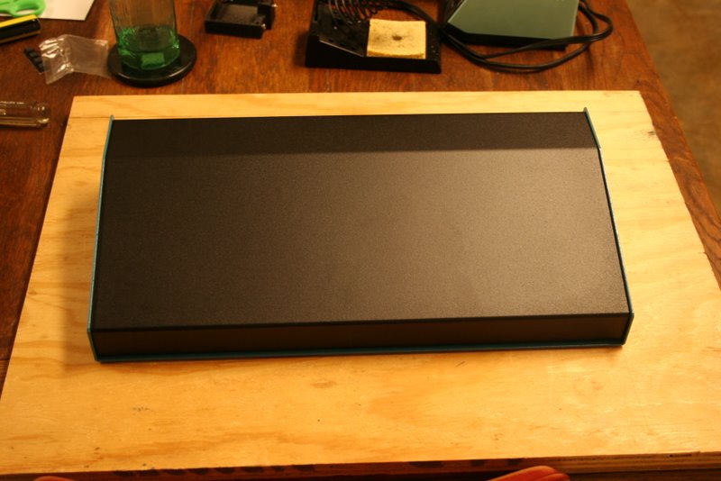
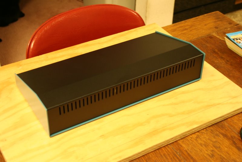
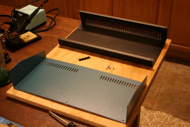
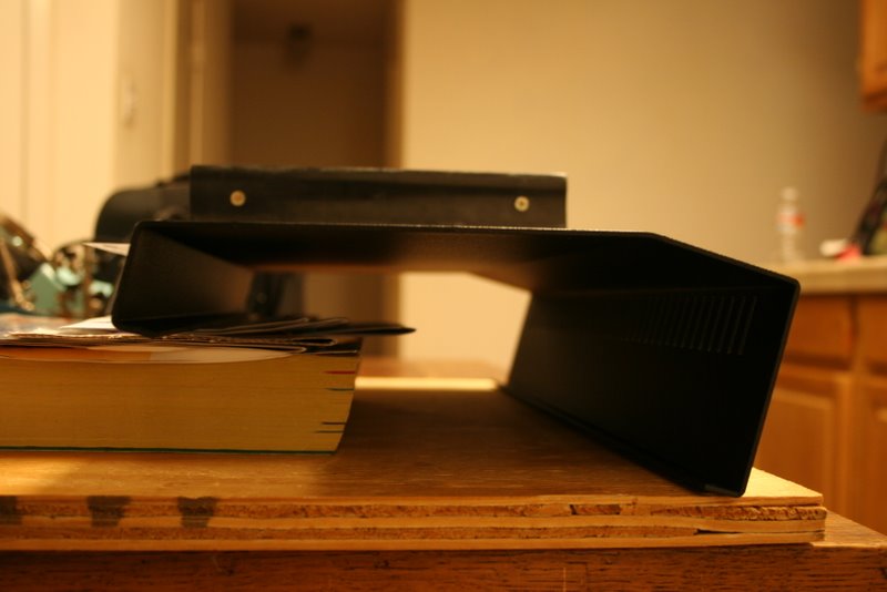
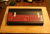
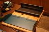
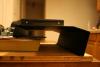
I ordered one of the cases I posted about earlier to see if it might work for MB-SEQ. I attached a few pics (hope this works on the new forum!). There are a few additional pics at http://picasaweb.google.com/fussylizard/MBSEQ?authkey=Gv1sRgCNOjnpP9tZzBTg&feat=directlink. I talked to Front Panel Express and they said they could machine the top surface and possibly the rear surface as well. I'll get them to look at the pics and confirm. The case is a little longer front to back than I would like, but still a possible off-the-shelf option, and there should be plenty of space for a power supply, AOUT_NG, maybe an SSM filter, etc. Will keep everyone posted...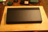

-
bread, lettuce, tomato, cheese, etc. Oh, sorry, it's nearly dinner time... :wacko:
-
If you're running the IIC loopback test off the MIOS8 download page, then that won't work which might be part of the issue here. Are you building a standalone core board or the MB-6582? I'm guessing the former. Have you tried using Smart mode for uploads? Do you have an LCD attached? If so, what does it say?
-
Like lylehaze suggested, try Smart mode. One other thing that occurred to me when looking at your second screenshot. I was pulling my hair out a few months ago with upload problems seeing similar messages about overwriting MIOS, etc. like you are getting. Turned out I had ordered the wrong PIC from SmashTV. Double-check that the .hex file you are uploading will work with the PIC you have. I'm not sure if this can be a problem with all apps or just with the bootloader or what, but double check that the PIC you have will work with what you are trying to do. MB-SID projects require a different PIC than other MIDIbox projects (due to the CAN bus) so you might want to double check PIC versions, or see if there are multiple .hex files for some of these test apps and be sure you are using the one for the PIC you have.