

Antichambre
-
Posts
1,291 -
Joined
-
Last visited
-
Days Won
101
Content Type
Profiles
Forums
Blogs
Gallery
Everything posted by Antichambre
-
 Hi Peter, My first intention was to implement a "mini CS" to change patch, bank...But i think it's not necessary, I only use the MasMsp Manager. But I let encoder and 4Digit on definitive PCB, (yet designed), we are not obliged to put and use it and it's difficult to cut squared hole in cartridge. Maybe one day firmware will be an MB-link one! You asked me for demo sound, you can find it on the blog!!!
 -
From the album: Antichambre "stuff and work"
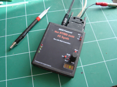
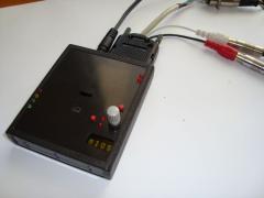
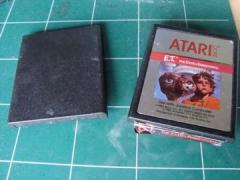
8 bit Atari 2600 MIDI Fx Synth -
From the album: Antichambre "stuff and work"
-
From the album: Antichambre "stuff and work"
-
From the album: Antichambre "stuff and work"
-
From the album: Antichambre "stuff and work"
-
From the album: Antichambre "stuff and work"
-
From the album: Antichambre "stuff and work"
-
From the album: Antichambre "stuff and work"
-
From the album: Antichambre "stuff and work"
-
From the album: Antichambre "stuff and work"
-
From the album: Antichambre "stuff and work"
-
From the album: Antichambre "stuff and work"
-
From the album: Antichambre "stuff and work"
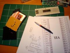
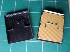
The original Atari Cartridge, broken E.T. game. -

MB-TIA Cartridge. Max Manager Software and Drum Kit Sound Demo.
Antichambre posted a blog entry in Antichambre's Blog
Firmware is working. Manager is ready. Features: 2 dedicated envelopes with optional non-linear curve for each voice, which can be assigned to Pitch and Volume2 additional envelopes with optional non-linear curve which can be assigned to Pitch and Volume 4 additional LFOs with different waveforms which can be assigned to Pitch and Volume Pitch Bender Portamento with optional "Constant Time Glide" function Delays Arpeggiator Poly, Mono, Multi and Legato Mode Separate keyboard zones for each voice (key splitting) allows to play voices separately Free controller assignments to Modulation Velocity AUD0, Velocity AUD1, Wheel and Aftertouch Wave and CC sequences which allow more percussive sounds2 Wavetables, 3 modes (Single 1x32, double 2x16 and Kit)In Kit Mode Wavetable is used as Key mapping tableThe wavetable sequencer can be combined with the arpeggiator in order to realize complex textures LFOs, Envelopes, Wavetables, Arpeggios optionally syncable via external MIDI clock OS independent MaxMsp Manager BankStick support (128 sound patches per stick, up to 2 are internally connected) MaxMsp Manager: Here preset(patch) is 'Drum Kit 1' - Voice Mode : Poly, max 2 notes at a time. - Wavetable Mode : Kit, one note / one sound. 'Drum Kit 1' Sound demo: Only one MIDI track, five differents sounds, for this drum pattern. The track starts with this five sounds. Next part: MB-TIA Cartridge. Final PCB. -
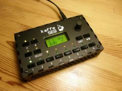 Rendez-vous at kaffe Machine! Great ... in french : C'est bon ça!!!
 -
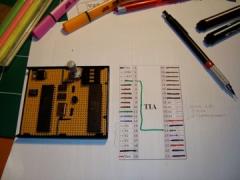
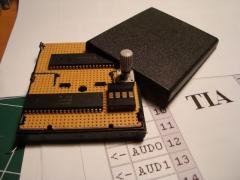
MB-TIA Cartridge. The TIA (Television Interface Adaptor)
Antichambre posted a blog entry in Antichambre's Blog
The Television Interface Adaptor(TIA) is the custom chip that is the heart of the Atari 2600 game console, generating the screen display, sound effects, and reading input controller. I/O Pin: Clock and CPU Synchronization: The 3.58 MHz oscillator (OSC Pin) also clocks a divide by three counter on this chip whose output (1.19 Mhz) is buffered to drive an output pin called 00. This pin provides the input phase zero clock to the microprocessor which then produces the system 02 clock (1.19 Mhz). Thus, the final input clock is 02, you've just got to bypass CPU, pin 00 connected to pin 02 and reproduce the OSC stage. There's two types of OSC one for the NTSC (3,58Mhz) and another for PAL/Secam (3,54MHz) according to your country video norm. The frequency of clock running has a direct bearing on the sound generator. In PAL, sounds will drop a little in pitch (frequency) because of a slower crystal clock. Audio Output: Two independent audio generating circuits are included, each with programmable frequency, noise content, and volume control registers. 2 voices, named AUD0 and AUD1. With a TIA in NTSC version, each voice has its output (pin 12 & 13). In PAL version, the two voices are added to the same output (pin 13), pin 12 is used for carrier frequency modulation. So rather choose a NTSC version if you want 2 separate outputs. Synthesis: Each audio circuit consists of parts described below: Frequency Select: Clock pulses (at approximately 30 KHz) from the horizontal sync counter pass through a divide by N circuit which is controlled by the output code from a five bit frequency register (AUDF). This register can be loaded (written) by the microprocessor at any time, and causes the 30 KHz clocks to be divided by 1 (code 00000) through 32 (code 11111). This produces pulses that are digitally adjustable from approximately 30 KHz to 1 KHz and are used to clock the noise-tone generator. Noise-Tone Generator: This circuit contains a nine bit shift counter which may be controlled by the output code from a four bit audio control register(AUDC), and is clocked by the frequency select circuit. The control register can be loaded by the microprocessor at any time, and selects different shift counter feedback taps and count lengths to produce a variety of noise and tone qualities. Volume Select: The shift counter output is used to drive the audio output pad through four driver transistors that are graduated in size. Each transistor is twice as large as the previous one and is enable by one bit from the audio volume register (AUDV). This audio volume register may be loaded by the microprocessor at any time. As binary codes 0 through 15 are loaded, the pad drive transistors are enabled in a binary sequence. The shift counter output therefore can pull down on the audio output pad with 16 selectable impedance levels. Registers: There are 44 8-bit registers whose addresses are coded on 6 bits. AUDx registers adresses start @ 0x15 0x15=00010101 0x16=00010110 0x17=00010111 0x18=00011000 0x19=00011001 0x1a=00011010 So we need 4 bits of address only. And 5 bits max for data (frequency). Data bits 7,6,5 and Adress bit 6 are connected to ground. Adress bit 5 to 5v. Frequency registers AUDFx: This registers are limited to 32 values​​ (5 bits), and need to be reversed! Control registers AUDCx: These are 16 in number (4 bits). But some are the same or are silent. So only 10 waveforms are available. Volume registers AUDVx: 16 levels (4 bits). TIA Schematics and Documentation. Schematic for MBHP Platform, Thorsten style: mbhp_tia_v1.pdf Next part: MB-TIA Cartridge. Max Manager Software and Drum Kit Sound Demo. -
MB-TIA Cartridge. Presentation.
Antichambre commented on Antichambre's blog entry in Antichambre's Blog
My preferred game is Moon Patrol, an endless game :) . -
MB-TIA Cartridge. Presentation.
Antichambre commented on Antichambre's blog entry in Antichambre's Blog
The CS is not yet fully implemented and gonna be limited so i wrote a Manager with MaxMsp for test during prog (more comfortable) .I need to finish it (esthetic) cause it's part of the demo. I'm on it. But you can imagine, it's TIA with the SW of the MBSID V1, I kept all useful functionalities LFOs ENVS....obviously without filter and PW cause it doesn't exist on TIA. And it's polynomial synthesis, waveforms are fixed but wavetable can works too (to do). -
MB-TIA Cartridge. Presentation.
Antichambre commented on Antichambre's blog entry in Antichambre's Blog
THX next part tomorrow. The TIA. Maybe someone can help me to optimize the firmware, it works but we can do better. I knew I'd found some atari fan. ;) cool -
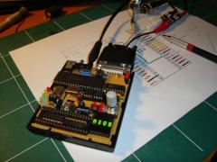
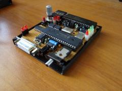
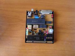
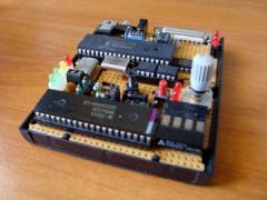
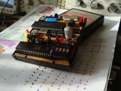
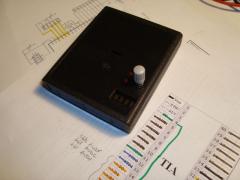
I'm probably a bit nostalgic for a time I played the game console in the living room of my parent. Need electronic sounds that have traumatized my childhood. The Atari 2600. I started this project 5 years ago. The first prototype I built was too big and too expensive to manufacture and not programmed into MIOS: A friend of mine recently reminded me that I had promised to make one for him(another nostalgic). So I resumed work in late 2010, after checking that no one already did. The first question was whether I was able to program it into MIOS. I tried and succeeded. Then I searched for housing. Why not in a game cartridge of the era!!! So i try it too. AND it fits in the box. The 2010 Proto next: The TIA (Television Interface Adapter) Atari chip.
-
 This is just an eps file at this time. With SidMonster, we are working on it. With printing/cutting machine and metallic inks on adhesive. gonna make a test and show result... "illskins" coming soon...
 -
 Thank you And YES! It was the goal. Some video? ;) It was not so difficult, Digital and Analog are clearly separated.
 -
Thank you guys! There's some analogic mods to do with KPR. ex: Bass Drum Mod. Maybe it can be controlled by midi? But for the moment, i don't reopen it, i play it!
-
From the album: Antichambre "stuff and work"
Midibox Powered