

FantomXR
-
Posts
1,035 -
Joined
-
Last visited
-
Days Won
22
Content Type
Profiles
Forums
Blogs
Gallery
Posts posted by FantomXR
-
-
Hi Peter,
sounds great! I'll try!
The only problem I have is, that this problem occurs random. It runs smooth for a while (like yesterday over 6h) or it can happen immediately (like today). Do you see a way to "force" this error? How did you check if the cap has the right value? Maybe I will add this cap not only to the last OLED but also to the 9th and see if that helps. Will do on tuesday hopefully.I don't use the onboard-regulators of the disco at all.
BTW: If you say "it was good enough for me" and "it solved nearly all my problems"... what are the problems you still have to deal with?
Thanks again! You saved me weekend ;-)
Best,
Chris -
So to clear it up: You suggest adding a small ceramic cap between CLK and GND and see if the problem is gone? You are right... if that solves the problem, it's the easiest way....
I'll try and report back!
Thanks!!//edit: I found that note:
https://www.diodes.com/assets/App-Note-Files/AB023.pdfThey suggest values between 50pF and 120pF if I understand it correctly:
AC termination is recommended most for clock applications. An example of AC termination is when a 75? impedance is coupled with a 100pF capacitor. To allow for leakage in input impedance of the receiver, the resistor is selected to be larger than the trace impedance. To allow for rapid transition of the clock edge, the capacitor value is selected at 120pF. A higher capacitor value allows for heavier current levels to pass. However, higher capacitive values increases power dissipation. Capacitor values less than 50pF diminish the effectiveness of termination. -
Hey guys,
thank you so much for your help.
@Andy: You are right: They both share the same GND. This has something to do with the LEDs. Those are WS2812B and they absolutely freak out if they have not the same GND as the core. This is why it's shared.
@Peter: Yes, I'll overwork my powersupply with super-stable-low-ripple-3.3V / 5V (doesn't matter on those OLEDs... they are brighter with 5V though). So, if buffering is the solution, how would the schematic look like? Could you give an advice how such a buffer works? Is there a documentation that I can adapt to my needs?
Thanks!!
Best,
Chris -
I pulled the LEDs from the power and now it worked till now. Now the 10th display is "shifted"....
I think I need to test your suggestion regarding connect RST to GND...
-
Meanwhile I think it maybe related to the power supply.... look at this...
The LEDs are powered from a separate power supply. So the OLEDs and LEDs do not share the same....
The powersupply contains of a 19V laptop-supply which than goes into LM2956-module to break it down to 5V.
-
Also another strange thing:
Yesterday I had the machine running for about 7h and it occurred at the end... today it happened already a few times.... strange... -
Dear Andy,
This should be correct. 8 CS signals come from the 595. The other two come from PC13 and PC14 of the core.
-
Dear andy
thanks for the suggestions.
To answer your questions: on this pcb there are 9 displays and another 6pin-connector on the very right or the pcb. A 10th display is connected through six 0.25 single wires to this 6pin connector pcb. Those have a length of about 35-40cm.
In the boot loader the number of displays is x=10, y=1
I need to mention that this effect occurred on the first display as well as on the 10th. All other displays were still running fine.
-
Dear Andy,
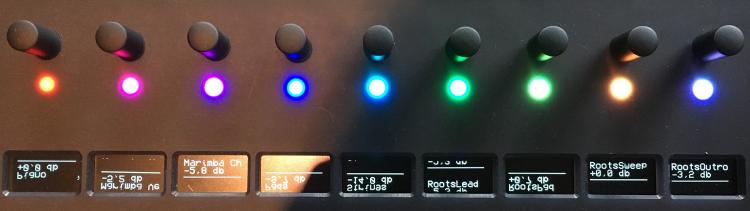
thanks for the reply! I uploaded the pictures into the gallery!
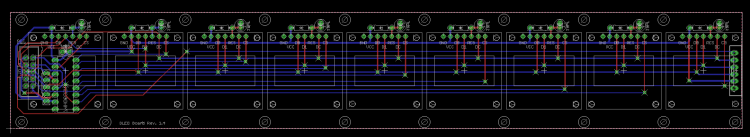
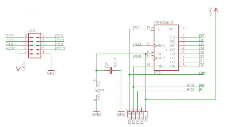
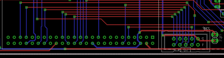
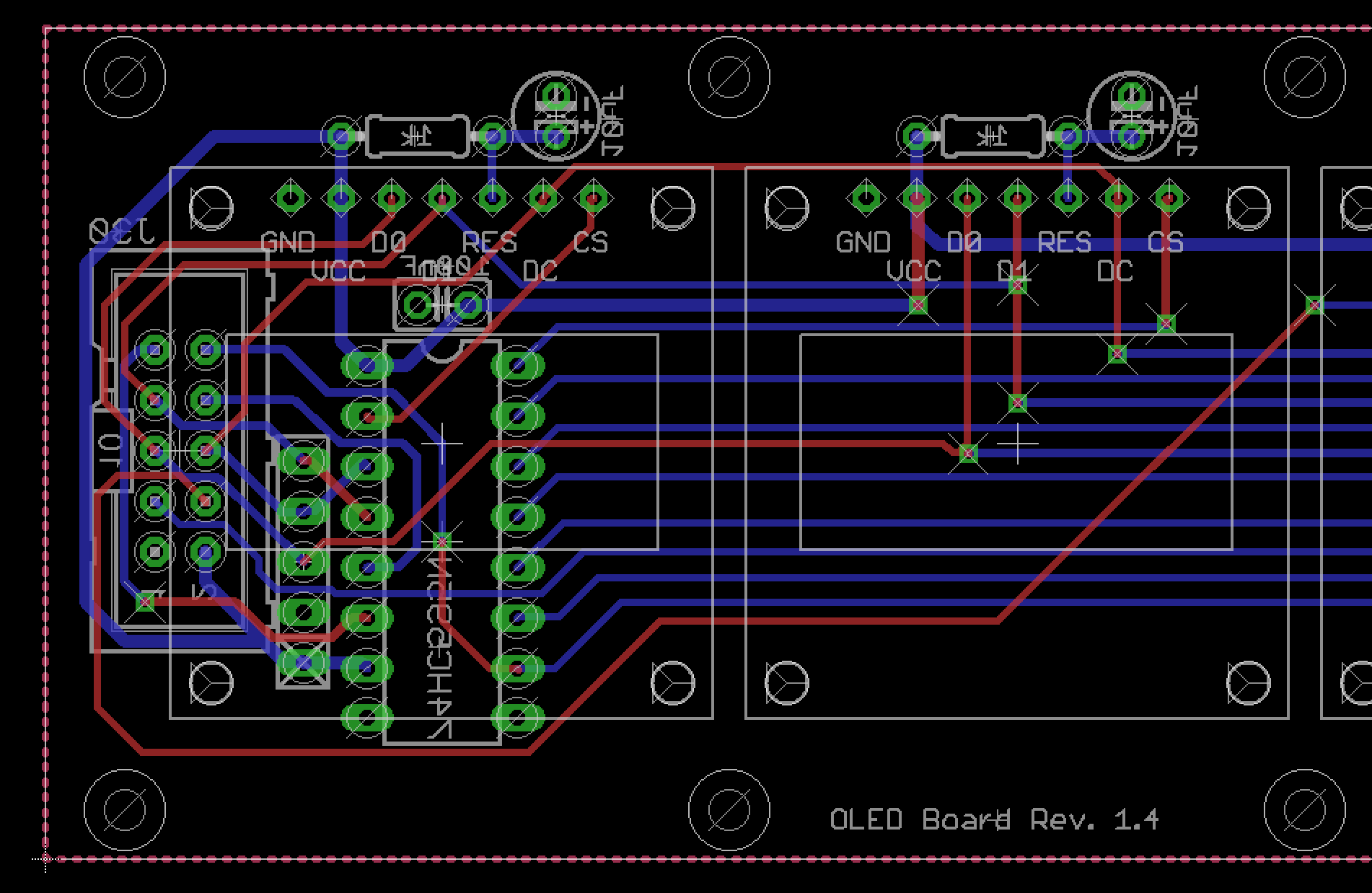
I designed my own core which has only the connectors on board, that I need. The core is connected through a 10cm ribbon cable to the OLEDs-PCB (there are 9 OLEDs on this PCB). The shift register, which is normally on the core PCB I've added to the OLED-PCB so I can save space on the core. The pinout of the connector you can see on the pictures:
OLED-PCB schematic:
OLED-PCB layout:

Core-layout:
Thank you for your help!
-
Hey people,
I have some problems with my OLEDs. Technical background: The OLEDs are mounted on a PCB and powered through a stable 5V power supply (they can be powered with 3.3V or 5V). Each OLED has a 1k resistor between RST and VDD and a 10uF cap between RST and VSS.
The OLEDs are triggered by NG. In NG I've added several receivers and senders, which translate sysex-streams into labels. That works very well... but!
I uploaded a picture where you can see the problem. Sometimes after using the MIDIbox for a while I get those errors. I'm really not sure what the problem is. I need to powercycle the midibox, to "reset" the displays. As you can see the whole label gets moved down and it will NOT reset by sending new sysex-events.
So, do you have an idea? Is it something in the firmware or is it hardware?
Maybe also @TK. can help ;-)
Thanks!!
Best,
Chris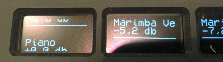
-
Hey people,
it looks like the NGR-function set_active is not working for senders and receivers. @TK.: Would you might have a look at it?
Best,
Chris -
Sure! This might work (didn't check yet). But I thought that there might be a much simpler way which says: take the note # and activate the RGBLED with the same ID. But it looks like, that's not possible...
And in the end you are right: I need to define every RGBLED anyway.... hm... alright! ;-)
I'll come up with another task these days... but I need to think about it first a bit more ;-)
-
I do not understand what you mean exactly.
If "use_key_number=0", the receiver passes the velocity to the fwd-element. If it's =1 it passes the note-number. That's clear.
But how do I "connect" the note-number with the corresponding ID of the RGBLED?
-
Hey people,
it's me again! ;-) Since @Zam helped me solving a problem, I have another one.
My setup is a keyboard and some RGBLEDs. If I now press C3 I'd like the corresponding RGBLED to light up. Of course I could do this by entering tons of receivers and senders but I'm looking for a smarter solution.I tried several things. The most promising was, that I'm able to convert the pressed key into another command f.e. if I press C3, NG outputs CC60, if I press B2, it outputs CC59, and so on.
What I'm looking for is kind of this (which is not working at the moment but it makes it more clear):
EVENT_RECEIVER id=1001 type=NoteOn key=any use_key_number=1 fwd_id=RGBLED:^valueThe last command is not supported in NGC. In NGR there is a ^value-command, but I can not use it for this purpose.
Any idea how to do that?
Thanks!
Best,
Chris -
@Zam: Thanks for this hint! It works now! ;-)
-
Good point. But I'll try that!!
-
Hey people,
I use a STM-core running MBKB for scanning my keybed. The core is connected to another core via direct-connection which works perfect. This core runs MB_NG. The 2nd core is connected to a computer.
I'd like to use the receiver / sender functionality to transform the notes coming from the keybed. So at first I set up the router which forwards the IN4 to USB1. This works great. Now I add a receiver. Something like this:EVENT_RECEIVER id=1001 type=NoteOn key=any use_key_number=1 fwd_id=SENDER:1001 EVENT_SENDER id=1001 type=CC cc=1What I'd expect is, that NG uses the key-number to output the corresponding cc-value. But that is not working. Also tried a very simple forwarding mechanism:
EVENT_RECEIVER id=1001 type=NoteOn key=any use_key_number=1 fwd_id=SENDER:1001
EVENT_SENDER   id=1001 type=NoteOn key=any use_key_number=1
Here I'd expect, that MB_NG generates the same notes twice at the USB1 output. The first coming from the router directly, the second from the receiver / sender. But this also doesn't work.
I'm sure that I overlook something. Does anyone have an idea?
Best,
Chris -
Dear TK,
thanks for your reply. Alright, I'll add this resistor.
For the other "problem" I'll try to add a hardware delay with RC circuit to prevent the LED from flashing.
-
Hey people,
I have two questions regarding the WS2812. If you read through the internet you will find various articles that one should use a resistor between DIN of the LED and the output-pin of the microcontroller. Is that also right for the STM32F4?
The second thing is, that the first (or sometimes an other) LED lights up short after a few seconds after powering the core (both share the same power supply). Any ideas how to prevent this?
Thanks,
Chris -
Hi,
I'm pretty sure that you will not achieve a result that comforts you or your father in law with normal switches.
There are other systems out on the market (PNOScan from QRS) which are perfect for this purpose because they use some kind of infrared-sensors and work without mechanical contact to the keys. This makes it very easy to set the deadbands and the correct brake / make points per key.Maybe you should save work and time and go with this system even if it's not that cheap (about 1200€ or so).
-
On 12.9.2017 at 1:53 PM, Zam said:
Definitely thinking your led draw enough current to cheat your 0V.
Might be! But today I tried to add two 0.5mm wires for GND and VRef.... without any success.
I checked again the NGC-File. I was wrong. I checked the faders at 7bit, which works okay and not with 11bit like I stated above. The jitter only happens when switching colors. With 11bit it doesn't even matter if the LEDs are connected. The fader jitter all the time.
Anyway: I really do not need 11bit on the faders. 7bit is totally sufficient. 11bit I do only need for the pitchbend-wheel. All other controllers (also foot controller) will work fine with 7bit. So if it would be possible to set the resolution on a per-pin-base, it would be the easiest solution. Maybe I could hardcode the pitchwheel.... I think I need to dig deeper into the code.
Maybe @TK. can help here?
-
I was at my local electronic-shop today and got a LM3940 which makes 3.3V out of 5V. And here is something strange:
Lets take the original schematic from the AINSER64 which is basically what I use. If I do not set the jumper J5 at all, I still am able to read out the potentiometer with nearly the full range (starts at 1 instead of 0 and goes up to 125 instead of 127). I'd expect that I either get jittering values or I'm not able to read out the potentiometer in total.
I tried to connect the 3.3V to the Vref of the MCP3208. Now I'd expect that I can read out the faders but wouldn't reach 127, because I have not configured them in the NGC via pinrange for 3.3V. But nothing changes here... I get the fullrange of the potentiometer. But jittering continues as soon as I change the colors on the LEDs....
//edit: I measured the voltage when connecting 3.3V to VREF. It seems to be right. At the faders I measure 3.3V and not 5V anymore. I'll do another test with a separate power supply for the LEDs again...
-
And two side notes:
I'm running at 11bit resolution and the faders I use are Bourns PTA4553 at 10k linear.
-
Sounds like a plan! I'll report! ;-) Thanks!


Problems with OLEDs over time
in MIDIbox NG
Posted
Oh yes... I'd be really interested in this... I'm really looking for a professional / proper solution that works at anytime....
The 5V that powers the core is indeed a switching PSU running a LM2596. But I need to add an LC filter to reduce output ripple. I'll try that and the pF-cap on the clock-pin and see if it improves it...
BTW: I worked with those OLEDs the whole last week without any problems! Than I moved with it to another place, and it went crazy.